

Page 1

E10-433MD-SMA User Manual
SI4463 433MHz 100mW DIP Wireless Module
Page 2

Chengdu Ebyte Electronic Technology Co., Ltd. E10-433MD-SMA User Manual
Copyright ©2012–2018,Chengdu Ebyte Electronic Technology Co.,Ltd.
1
目录
1 Overview.................................................................................................................................................................................................2
1.1 Brief introduction ......................................................................................................................................................................2
1.2 Feature .........................................................................................................................................................................................2
1.3 Application .................................................................................................................................................................................2
2 Spec ification and parameter ................................................................................................................................................................3
2.1 Limit parameter .........................................................................................................................................................................3
2.2 Operating para meter .................................................................................................................................................................3
3 Size and pin definition ..........................................................................................................................................................................4
4. Basic operation .....................................................................................................................................................................................5
4.1 Hardware design ................................................................................................................................................................5
4.2 Software ed iting ........................................................................................................................................................................5
5 Basic application .........................................................................................................................................................................6
5.1 Basic circuit diagram ................................................................................................................................................................6
6 FA Q..........................................................................................................................................................................................................6
6.1 Communication range is too short .........................................................................................................................................6
6.2 Module is easy to damage........................................................................................................................................................7
6.3 BER(Bit Error Rate) is high .................................................................................................................................................7
7 Production guidance..............................................................................................................................................................................7
7.1 Reflow soldering te mperature .................................................................................................................................................7
7.2 Reflow soldering curve ............................................................................................................................................................8
8 E10 Series ...............................................................................................................................................................................................8
9 Antenna guidance ..................................................................................................................................................................................9
9.1 Antenna recommendation ........................................................................................................................................................9
10 Package method for bulk order ...................................................................................................................................................... 10
Revision history ..................................................................................................................................................................................... 11
About us .................................................................................................................................................................................................. 11
Page 3
Chengdu Ebyte Electronic Technology Co., Ltd. E10-433MD-SMA User Manual
Copyright ©2012–2018,Chengdu Ebyte Electronic Technology Co.,Ltd.
2
1 Overview
1.1 Brief introduction
E10-433MD-SMA is DIP wireless module working at
433MHz developed bas ed on chip SI4463 from Silicon Labs.
Due to the use of the imported Si4463 as the core of the
module, its stability has been well received by us ers, and
compatibility is not a concern. The module is aimed at smart
home, wireless meter reading, scientific research and medical,
and medium and long distance wireless communicatio n
equipment. Since RF performance and component s election are in accordance with indus trial standards, and the product
has obtained FCC, CE, RoHs and other international authoritative certification reports, us ers do not need to worry about
its performance. With its stable and reliable characteristics, it is favored by the majority of us ers. Compared with the old
products, it has made great progres s in receiving current, receiving sens itivity, trans mitting power, receiving rate range an d
anti-interference ability. High precision 26MHz crystal is used.
Since the module is a pure RF transceiver module, you need to use the MCU driver or a dedicated SPI debug tool.
1.2 Feature
Communication distance tested is up to 2km
Maximum transmis s ion power of 100mW, software multi-level adjus table;
Support the global license-free ISM 433MHz band;
Support air date rate of 1.2kbps~1000kbps;
Support multiple modulation methods, (G)FSK, 4(G)FSK, (G)MSK,OOK ;
Support 64/128 byte Trans ceiver Data Register (FIFO);
Support 2.5V~3.6V power supply, power supply over 3.3 V can guarantee the best performance;
Industrial grade s tandard design, s upport -40 ~ 85 °C for working over a long time;
SMA connector, good for connecting external antenna.
1.3 Application
Home s ecurity alarm and remote keyless entry;
Smart home and industrial sensors ;
Wireless alarm security system;
Building automation solutions;
Wireless industrial-grade remote control;
Health care products;
Advanced Meter Reading Architecture(AMI);
Automotive industry applications .
Page 4
Chengdu Ebyte Electronic Technology Co., Ltd. E10-433MD-SMA User Manual
Copyright ©2012–2018,Chengdu Ebyte Electronic Technology Co.,Ltd.
3
2 Specification and parameter
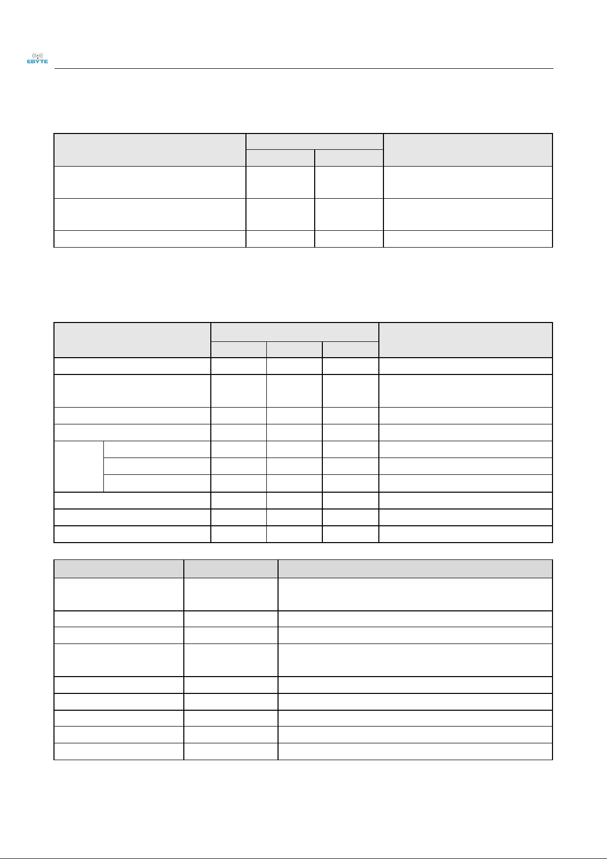
2.1 Limit parameter
Main parameter
Performance
Remark
Min.
Max.
Power supply(V)
0
3.6
Voltage over 3.6V will cause permanent
damage to module
Blocking power(dBm)
-
10
Chances of burn is slim when modules are
used in short distance
Operating temperature(℃)
-40
85
-
2.2 Operating parameter
Main parameter
Performance
Remark
Min.
Typ.
Max.
Operating voltage(V)
1.8
3.3
3.6
≥3.3 V ensures output power
Communication level(V)
-
3.3
-
For 5V TTL, it may be at risk of burning
down
Operating temperature(℃)
-40 - 85
Industrial design
Operating frequency(MHz)
425
433
525
Support ISM band
Power
consumpti
on
TX current(mA)
-
80
-
Instant power consumption
RX current(mA)
-
13
-
-
Sleep current (μA)
-
0.6
-
Software is shut down
Max Tx power(dBm)
19
20
21
-
Receiving sensitivity(dBm)
-124
-126
-128
Air data rate is 1kbps
Air data rate(bps)
0.123k
-
1M
Controlled via user’s programming
Main parameter
Description
Remark
Distance for reference
2000m
Test condition:clear and open area, antenna gain: 5dBi,antenna
height: 2.5m,air data rate: 1kbp s
FIFO
64Byte
Max length transmitted each time
Crystal frequency
26MHz
-
Modulation
GFSK
(recommended)
(G)FSK, 4(G)FSK, (G)MSK,OOK
Package
DIP
-
Connector
1.5mm
-
Communication interface
SPI
0-10Mbps
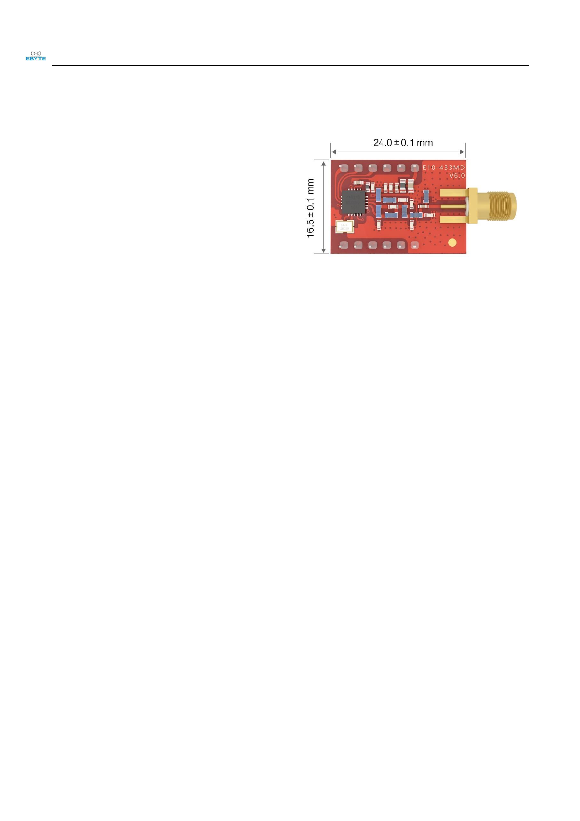
Size
16.6 *24mm
-
Antenna
SMA-K
50 ohm impedance
Page 5

Chengdu Ebyte Electronic Technology Co., Ltd. E10-433MD-SMA User Manual
Copyright ©2012–2018,Chengdu Ebyte Electronic Technology Co.,Ltd.
4
3 Size and pin definition
No.
Name
Direction
Function
1
GND
-
Ground
2
SDN
-
Shutdown Input Pin. It is low level when working
(See SI4463 manual for more details)
3
GPIO3
output
GPIO(see more from SI4463 datasheet)•
4
GPIO2
output
GPIO(see more from SI4463 datasheet)•
5
nSEL
input
SPI Chip select for starting SPI communication
6
MOSI
input
SPI master output slave inp ut
7
MISO
output
SPI master input slave outp ut
8
SCK
input
Serial Clock Input
9
IRQ
output
SPI interrupt request
10
GPIO1
output
GPIO(see more from SI4463 datasheet)•
11
GPIO0
output
GPIO(see more from SI4463 datasheet)•
12
VCC
-
Power sup p ly :1.8~ 3.6 V DC, 3.3V is recommended
Page 6

Chengdu Ebyte Electronic Technology Co., Ltd. E10-433MD-SMA User Manual
Copyright ©2012–2018,Chengdu Ebyte Electronic Technology Co.,Ltd.
5
4. Basic operation
4.1 Hardware design
It is recommended to us e a DC stabilized power supply. The power supply ripple factor is as small as possible, and
the module needs to be reliably grounded.;
Please pay attention to the correct connection of the positive and negative poles of the power supply. Reverse
connection may cause permanent damage to the module;
Please check the power supply to ensure it is within the recommended voltage otherwise when it exceeds the
maximu m value the module will be permanently damaged;
Please check the s tability of the power supply, the voltage can not be fluctuated frequently ;
When designing the power s upply circuit for the module, it is often recommended to reserve more than 30% of the
margin, so the whole machine is beneficial for long -term stable operation.;
The module should be as far away as pos s ible from the power supply, trans formers, high -frequency wiring and other
parts with large electromagnetic interference.;
High-frequency digital routing, high-frequency analog routing, and power routing must be avoided under the module.
If it is neces s ary to pass through the module, ass ume that the module is soldered to the Top Layer, and the copper is
spread on the Top Layer of the module contact part(well grounded), it mus t be close to the digital part of the module
and routed in the Bottom Layer;
As suming the module is soldered or placed over the Top Layer, it is wrong to randomly route over the Bottom Layer
or other layers, which will affect the module's s purs and receiving sens itivity to varying degrees ;
It is assumed that there are devices with large electromagnetic interference around the module that will greatly affe ct
the performance. It is recommended to keep them away from the module according to the s trength of the interference.
If necessary, appropriate isolation and shielding can be done ;
As sume that there are traces with large electromagnetic interference (high-frequency digital, high-frequency analog,
power traces) around the module that will greatly affect the performance of the module. It is recommended to s tay
away from the module according to the s trength of the interference.If neces sary, appropriate isolation and shielding
can be done.
If the communication line uses a 5V level, a 1k-5.1k resistor must be connected in series (not recommended, there is
still a risk of damage);
Try to s tay away from some phys ical layers such as TTL protocol at 2.4GHz , for example: USB3.0;
The mounting structure of antenna has a great influence on the performance of the module. It is neces sary to ensure
that the antenna is expos ed, preferably vertically upward. When the module is mounted inside the cas e, us e a good
antenna extension cable to extend the antenna to the outside;
The antenna must not be installed inside the metal case, which will cause the transmis sion distance to be greatly
weakened.
4.2 Software editing
GPIO0 \ GPIO1 \ GPIO2 \ GPIO3 are configurable I/O ports for various application ,s ee more in SI4463 datasheet.It
can be floated when not us ed.
Page 7

Chengdu Ebyte Electronic Technology Co., Ltd. E10-433MD-SMA User Manual
Copyright ©2012–2018,Chengdu Ebyte Electronic Technology Co.,Ltd.
6
IRQ pin can also be disconnected. The SPI query mode can be used to obtain the interrupt status. However, it is
recommended to us e the external interrupt of the MCU.
SPI communication rate should not be set too high, usually around 1Mbps.
Please refer to “Operating Modes and Timing ” for SI4463 status switch,the switch between TX and RX should be
through Ready, can not be switched directly.
Re-initialize register configuration when the chip is idle for higher stability.
For controlling GPIO2 ,GPIO3 externally,pin status is as follows:
In tx mode:GPIO2 = 0; GPIO3 = 1;
In rx mode:GPIO2 = 1; GPIO3 = 0;
If the SI4463 is required to control itself, the mode of the configuration pins can be as follows when
the program is initialized:
SI44XX_GPIO_CONFIG( 0, 0, 32|0x40, 33|0x40, 0, 0, 0 );
5 Basic application
5.1 Basic circuit diagram
6 FAQ
6.1 Communication range is too short
The communication distance will be affected when obstacle exis ts.
Data lose rate will be affected by temperature, humidity and co -channel interference.
The ground will absorb and reflect wireless radio wave, so the performance will be poor when testing near groun d.
Sea water has great ability in absorbing wireless radio wave, so performance will be poor when testing near the s ea.
The signal will be affected when the antenna is near metal object or put in a metal cas e.
Power register was set incorrectly, air data rate is set as too high (the higher the air data rate, the shorter the
distance).
Page 8

Chengdu Ebyte Electronic Technology Co., Ltd. E10-433MD-SMA User Manual
Copyright ©2012–2018,Chengdu Ebyte Electronic Technology Co.,Ltd.
7
The power s upply low voltage under room temperature is lower than 2.5V, the lower the voltage, the lower the
trans mitting power.
Due to antenna quality or poor matching between antenna and module.
6.2 Module is easy to damage
Please check the power s upply s ource, ensure it is 2.0V~3.6V, voltage higher than 3.6V will damage the module.
Please check the s tability of power source, the voltage cannot fluctuate too much.
Please make sure antistatic meas ure are taken when ins talling and using, high frequency devices have electros tatic
susceptibility.
Please ensure the humidity is within limited range, some parts are sensitive to humidity.
Please avoid us ing modules under too high or too low temperature.
6.3 BER(Bit Error Rate) is high
There are co-channel signal interference nearby, please be away from interference sources or modify frequency and
channel to avoid interference;
Poor power supply may caus e mess y code. Make sure that the power supply is reliable.
The extension line and feeder quality are poor or too long, s o the bit error rate is high;
7 Production guidance
7.1 Reflow soldering temperature
Profile Feature
Curve characteristics
Sn-Pb Assembly
Pb-Free Assembly
Solder Paste
Solder paste
Sn63/Pb37
Sn96.5/Ag3/Cu0.5
Preheat Temperature min (Tsmin)
Min preheating temp.
100℃
150℃
Preheat temperature max (Tsmax)
Mx preheating temp.
150℃
200℃
Preheat Time (Tsmin to Tsmax)(ts)
Preheating time
60-120 sec
60-120 sec
Average ramp-up rate(Tsmax to Tp)
Average ramp-up rate
3℃/second max
3℃/second max
Liquidous Temperature (TL)
Liquid phase temp.
183℃
217℃
Time(tL)Maintained Above(TL)
Time below liquid phase line
60-90 sec
30-90 sec
Peak temperature(Tp)
Peak temp.
220-235℃
230-250℃
Aveage ramp-down rate(Tp to Tsmax)
Aveage ramp-down rate
6℃/second max
6℃/second max
Time 25℃ to peak temperature
Time to peak temperature for
25℃
max 6 minutes
max 8 minutes
Page 9

Chengdu Ebyte Electronic Technology Co., Ltd. E10-433MD-SMA User Manual
Copyright ©2012–2018,Chengdu Ebyte Electronic Technology Co.,Ltd.
8
7.2 Reflow soldering curve
8 E10 Series
Model No.
IC
Frequency
(Hz)
Tx power
(dBm)
Test distance
km
Package
Antenna
E10-868MS30
SI4463
868M
30 6 SMD
Stamp hole/IPEX
E10-915MS20
SI4463
915M
20
2.5
SMD
Stamp hole/IPEX
E10-868MS20
SI4463
868M
20
2.5
SMD
Stamp hole/IPEX
E10-433MS1W
SI4463
433M
30 6 SMD
Stamp hole
E10-433MD3
SI4438
433M
20 2 SMD
IPEX
E10-433MD-SMA
SI4463
433M
20 2 DIP
SMA-K
E10-433MS
SI4463
433M
20 2 SMD
Stamp hole
Page 10

Chengdu Ebyte Electronic Technology Co., Ltd. E10-433MD-SMA User Manual
Copyright ©2012–2018,Chengdu Ebyte Electronic Technology Co.,Ltd.
9
9 Antenna guidance
9.1 Antenna recommendation
The antenna is an important role in the communication process. A good antenna can largely improve the
communication s ystem. Therefore, we recommend some antennas for wireless modules with excellent performance and
reasonable price.
Model No.
Type
Frequency
Hz
Interface
Gain
dBi
Height
Cable
Function feature
TX433-NP-4310
PCB
433M
SMA-J
2
43.8*9.5mm
-
Built-in FPC antenna
TX433-JW-5
Rubber
433M
SMA-J
2
50mm
-
Flexible &omnidirectional
TX433-JWG-7
Rubber
433M
SMA-J
2.5
75mm
-
Flexible &omnidirectional
TX433-JK-20
Rubber
433M
SMA-J
3
210mm
-
Flexible &omnidirectional
TX433-JK-11
Rubber
433M
SMA-J
2.5
110mm
-
Flexible &omnidirectional
TX433-XP-200
Sucker
433M
SMA-J
4
19cm
200cm
Sucker antenna, High gain
TX433-XP-100
Sucker
433M
SMA-J
3.5
18.5cm
100cm
Sucker antenna, High gain
TX433-XPH-300
Sucker
433M
SMA-J
6
96.5cm
300cm
Big sucker antenna,ultra
high gain
TX433-JZG-6
Rubber
433M
SMA-J
2.5
52mm
-
Short straight
&omnidirectional
TX433-JZ-5
Rubber
433M
SMA-J
2
52mm
-
Short straight
&omnidirectional
Page 11

Chengdu Ebyte Electronic Technology Co., Ltd. E10-433MD-SMA User Manual
Copyright ©2012–2018,Chengdu Ebyte Electronic Technology Co.,Ltd.
10
10 Package method for bulk order
Page 12

Chengdu Ebyte Electronic Technology Co., Ltd. E10-433MD-SMA User Manual
Copyright ©2012–2018,Chengdu Ebyte Electronic Technology Co.,Ltd.
11
Revision history
Version
Date
Description
Iss ued by
1.00
2017/10/16
Initial version
huaa
1.10
2018/5/23
Content updated
huaa
1.20
2018/9/19
Model No. split
Huaa
About us
Technical support: s upport@cdebyte.com
Documents and RF Setting download link: www.ebyte.com
Thank you for us ing Ebyte products! Please contact us with any ques tions or suggestions: info@cdebyte.com
--------------------- -- --- -- -- -- --- -- -- -- ----------------------------------------- -- --- -- -- -- --- -- -- -- ------
Fax: 028-64146160 ext. 821
Web: www.ebyte.com
Address: Innovation Center B333-D347, 4# XI-XIN Road,Chengdu, Sichuan, China
 Loading...