

Page 1

E01-2G4M13S User Manual
NRF24L01P 2.4GHz SMD Wireless Module
Page 2
Chengdu Ebyte Electronic Technology Co., Ltd. E01-2G4M13S User Manual
1
E01-2G4M13S is a wireless serial port module (UART) based on
Nordic's NRF24L01P RF chip, working in 2.4ghz with built-in PCB
antenna.
Since chip nRF24L01P is used to ensure compatibility, the power
amplifier (PA) and low noise amplifier (LNA) are built on the original basis,
the maximum transmit power reaches 20mW and the receiving sensitivity
Communication distance tested is up to 800m;
Maximum transmission power of 20mW, software multi-level adjustable;
Support the global license-free ISM 2.4GHz;
Support air date rate of 2Mbps,1Mbps and 250kbps;
125 communication channels to meet the needs of multi-point communication, grouping, frequency
Connect to the MCU through the SPI interface at a rate of 0~10Mbps;
Support 2.0V~3.6V power supply, power supply over 3.3V can guarantee the best performance;
Industrial grade standard design, support -40 ~ 85 °C for working over a long time;
Onboard PCB antenna, no need to connect external antenna;
Enhanced ShockBurst, fully compatible with nRF24L, nRF24E, nRF24U series of NORDIC.
1 Overview
1.1 Introduction
is further improved. Communication stability is greatly improved compared to products without power amplifiers
and low noise amplifiers. A large number of domestic Si24R1s are used in the market to pretend to be nRF24L01P
produced by NORDIC. it is recommended that the user tests the communication stability and distance under the
real use scenario and the difference is very obvious. Industrial grade high precision 16MHz crystal is used. This
product has obtained domestic and international authoritative certification such as FCC, CE, RoHS, etc.
Since the E01-2G4M13S is a SPI RF transceiver module, you need to use the MCU driver or a dedicated SPI
debugging tool.
1.2 Features
hopping, etc.;
Copyright ©2012–2018,Chengdu Ebyte Electronic Technology Co.,Ltd
Page 3
Chengdu Ebyte Electronic Technology Co., Ltd. E01-2G4M13S User Manual
2
Home security alarm and remote keyless entry;
Smart home and industrial sensors;
Wireless alarm security system;
Building automation solutions;
Wireless industrial-grade remote control;
Health care products;
Advanced Meter Reading Architecture(AMI);
Automotive industry applications.
Main parameter
Performance
Remark
Min.
Max.
Power supply(V)
0
3.6
Voltage over 3.6V will cause permanent
damage to module
Blocking power(dBm)
-
10
Chances of burn is slim when modules
are used in short distance
Operating temperature(℃)
-40
85
/
Main parameter
Performance
Remark
Min.
Typ.
Max.
Operating voltage(V)
2.0
3.3
3.6
≥3.3 V ensures output power
Communication level(V)
3.3
For 5V TTL, it may be at risk of burning
down
Operating temperature(℃)
-402585
Industrial design
Operating frequency(MHz)
2.4-2.525
Support ISM band
Power
consump
tion
TX current(mA)
-38-
Instant power consumption
RX current(mA)
-
16.8
-
Sleep current (μA)
-
1.2-Software is shut down
Max Tx power(dBm)
12.51313.5
Receiving sensitivity(dBm)
-97
-98
-99
Air data rate is 250 kbps
Air data rate(bps)
250k
250k
2M
Controlled via user’s programming
1.3 Application
2 Specification and parameter
2.1 Limit parameter
2.2 Operating parameter
Copyright ©2012–2018,Chengdu Ebyte Electronic Technology Co.,Ltd
Page 4

Chengdu Ebyte Electronic Technology Co., Ltd. E01-2G4M13S User Manual
3
Main parameter
Description
Remark
Distance for reference
800m
Test condition:clear and open area, antenna gain: 5dBi,
antenna height: 2.5m,air data rate: 250kbps
FIFO
32 Bytes
Max. Transmitting length per packet
Crystal frequency
16MHz
Modulation
GFSK
Package
SMD
Connector
1.27mm
Communication interface
SPI
0-10Mbps
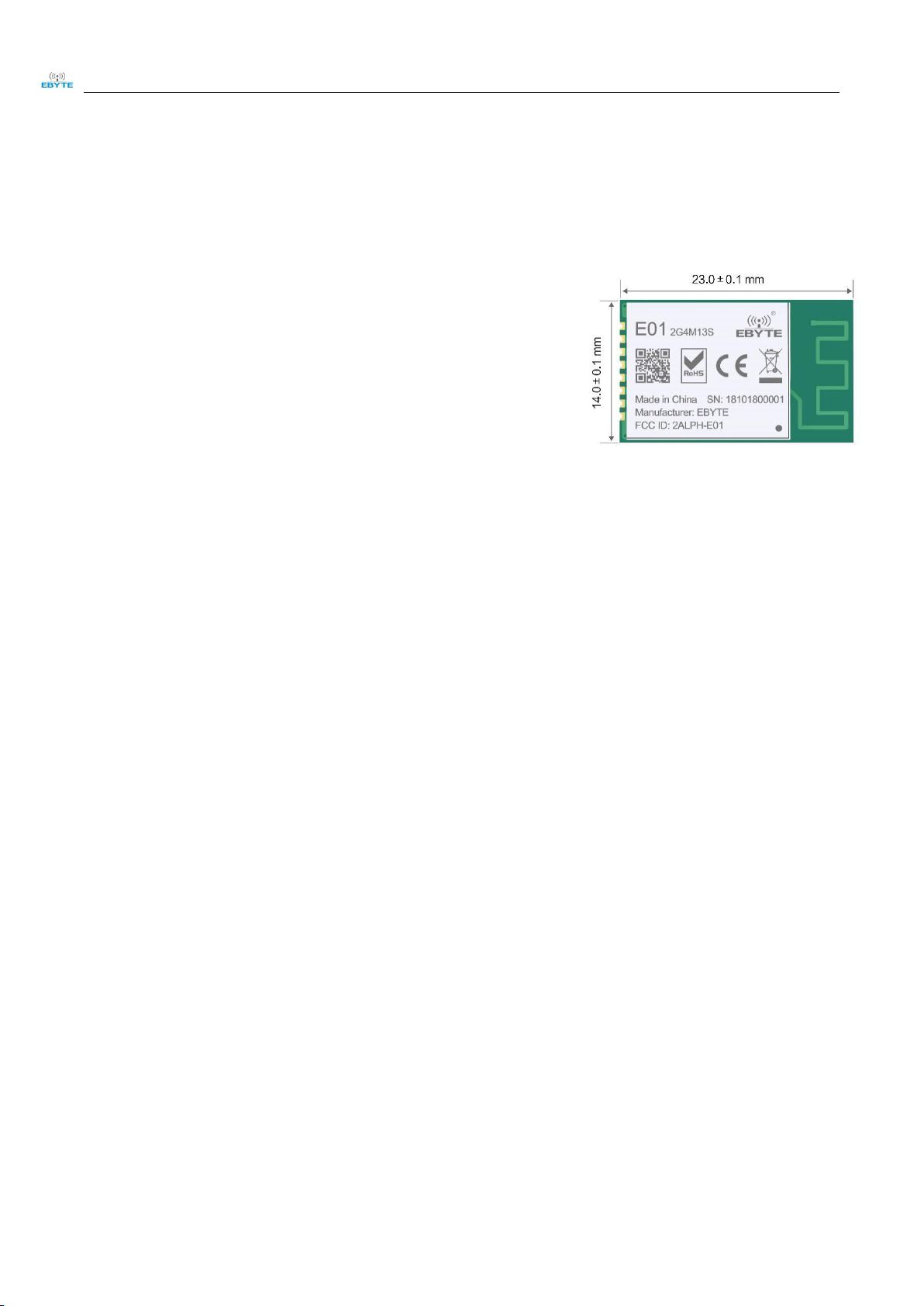
Size
14 * 23 mm
PCB antenna included
Antenna
PCB antenna
50 ohm impedance
3 Size and pin definition
Copyright ©2012–2018,Chengdu Ebyte Electronic Technology Co.,Ltd
Page 5

Chengdu Ebyte Electronic Technology Co., Ltd. E01-2G4M13S User Manual
4
No.
Name
Direction
Function
1
VCC
Power supply
Power supply :2.0~ 3.6V DC
2
CE
Input
Chip enable
3
CSN
Input
SPI Chip select
4
SCK
Input
SPI Clock
5
MOSI
Input
SPI master output slave input
6
MISO
Output
SPI master input slave output
7
IRQ
Output
Interrupt request, valid in low communication level
8
GND
Ground
9
GND
Ground
10
GND
Ground
4.1 Hardware design
It is recommended to use a DC stabilized power supply. The power supply ripple factor is as small as possible,
Please pay attention to the correct connection of the positive and negative poles of the power supply.
Please check the power supply to ensure it is within the recommended voltage otherwise when it exceeds the
Please check the stability of the power supply, the voltage can not be fluctuated frequently;
When designing the power supply circuit for the module, it is often recommended to reserve more than 30%
The module should be as far away as possible from the power supply, transformers, high-frequency wiring
High-frequency digital routing, high-frequency analog routing, and power routing must be avoided under
Assuming the module is soldered or placed over the Top Layer, it is wrong to randomly route over the
It is assumed that there are devices with large electromagnetic interference around the module that will
4 Basic operation
and the module needs to be reliably grounded.;
Reverse connection may cause permanent damage to the module;
maximum value the module will be permanently damaged;
of the margin, so the whole machine is beneficial for long-term stable operation.;
and other parts with large electromagnetic interference.;
the module. If it is necessary to pass through the module, assume that the module is soldered to the Top
Layer, and the copper is spread on the Top Layer of the module contact part(well grounded), it must be close
to the digital part of the module and routed in the Bottom Layer;
Bottom Layer or other layers, which will affect the module's spurs and receiving sensitivity to varying
degrees;
greatly affect the performance. It is recommended to keep them away from the module according to the
strength of the interference. If necessary, appropriate isolation and shielding can be done;
Copyright ©2012–2018,Chengdu Ebyte Electronic Technology Co.,Ltd
Page 6

Chengdu Ebyte Electronic Technology Co., Ltd. E01-2G4M13S User Manual
5
Assume that there are traces with large electromagnetic interference (high-frequency digital, high-frequency
If the communication line uses a 5V level, a 1k-5.1k resistor must be connected in series (not recommended,
Try to stay away from some physical layers such as TTL protocol at 2.4GHz , for example: USB3.0;
Onboard PCB antennas should avoid conductors or other sources of interference.
Insert the module on the user's circuit board, use the microcontroller to communicate with the module via SPI
IRQ is an interrupt pin, which can be used to wake up the microcontroller and achieve fast response. If it is
CE can be connected to a high level for a long time, but the module must first be set to the POWER DOWN
analog, power traces) around the module that will greatly affect the performance of the module. It is
recommended to stay away from the module according to the strength of the interference.If necessary,
appropriate isolation and shielding can be done.
there is still a risk of damage);
4.2 Software editing
or serial port, and operate the control register and the transceiver buffer through the SPI command to
complete the wireless data transmitting and receiving function. For the timing operation of the read and write
operations for the module register, please refer to the latest nRF24L01P data sheet.
not connected, the SPI query mode can be used to obtain the interrupt status (not recommended, which is
not conducive to the overall power consumption, and the efficiency is not enough);
mode when writing the register. It is recommended that the CE be controlled by a MCU pin.
5 Basic application
5.1 Basic circuit diagram
6 FAQ
6.1 Communication range is too short
Copyright ©2012–2018,Chengdu Ebyte Electronic Technology Co.,Ltd
Page 7

Chengdu Ebyte Electronic Technology Co., Ltd. E01-2G4M13S User Manual
6
The communication distance will be affected when obstacle exists.
Data lose rate will be affected by temperature, humidity and co-channel interference.
The ground will absorb and reflect wireless radio wave, so the performance will be poor when testing near ground.
Sea water has great ability in absorbing wireless radio wave, so performance will be poor when testing near the sea.
The signal will be affected when the antenna is near metal object or put in a metal case.
Power register was set incorrectly, air data rate is set as too high (the higher the air data rate, the shorter the distance).
The power supply low voltage under room temperature is lower than 2.5V, the lower the voltage, the lower the
Due to antenna quality or poor matching between antenna and module.
Please check the power supply source, ensure it is 2.0V~3.6V, voltage higher than 3.6V will damage the module.
Please check the stability of power source, the voltage cannot fluctuate too much.
Please make sure antistatic measure are taken when installing and using, high frequency devices have electrostatic
Please ensure the humidity is within limited range, some parts are sensitive to humidity.
Please avoid using modules under too high or too low temperature.
There are co-channel signal interference nearby, please be away from interference sources or modify
Poor power supply may cause messy code. Make sure that the power supply is reliable.
The extension line and feeder quality are poor or too long, so the bit error rate is high;
Profile Feature
Curve characteristics
Sn-Pb Assembly
Pb-Free Assembly
Solder Paste
Solder paste
Sn63/Pb37
Sn96.5/Ag3/Cu0.5
Preheat Temperature min (Tsmin)
Min preheating temp.
100℃
150℃
Preheat temperature max (Tsmax)
Mx preheating temp.
150℃
200℃
Preheat Time (Tsmin to Tsmax)(ts)
Preheating time
60-120 sec
60-120 sec
Average ramp-up rate(Tsmax to Tp)
Average ramp-up rate
3℃/second max
3℃/second max
Liquidous Temperature (TL)
Liquid phase temp.
183℃
217℃
Time(tL)Maintained Above(TL)
Time below liquid phase line
60-90 sec
30-90 sec
Peak temperature(Tp)
Peak temp.
220-235℃
230-250℃
Aveage ramp-down rate(Tp to Tsmax)
Aveage ramp-down rate
6℃/second max
6℃/second max
Time 25℃ to peak temperature
Time to peak temperature for
25℃
max 6 minutes
max 8 minutes
transmitting power.
6.2 Module is easy to damage
susceptibility.
6.3 BER(Bit Error Rate) is high
frequency and channel to avoid interference;
7 Production guidance
7.1 Reflow soldering temperature
Copyright ©2012–2018,Chengdu Ebyte Electronic Technology Co.,Ltd
Page 8

Chengdu Ebyte Electronic Technology Co., Ltd. E01-2G4M13S User Manual
7
Model No.
RFIC
Frequency
TX power
Distance
Package
Antenna
Hz
dBm
km
E01-ML01S
nRF24L01P
2.4G00.1
SMD
PCB
E01-ML01D
nRF24L01P
2.4G00.1
DIP
PCB
E01-ML01IPX
nRF24L01P
2.4G00.2
SMD
IPEX
E01-2G4M13S
nRF24L01P
2.4G130.8
SMD
PCB
E01-ML01DP4
nRF24L01P
2.4G201.8
DIP
PCB
E01-ML01DP5
nRF24L01P
2.4G202.5
DIP
SMA-K
E01-ML01SP2
nRF24L01P
2.4G201.8
SMD
PCB/IPEX
E01-ML01SP4
nRF24L01P
2.4G202
SMD
IPEX
E01-2G4M27D
nRF24L01P
2.4G275
DIP
SMA-K
All E01 series module are compatible with each other.
7.2 Reflow soldering curve
8 E01 Series
Copyright ©2012–2018,Chengdu Ebyte Electronic Technology Co.,Ltd
Page 9

Chengdu Ebyte Electronic Technology Co., Ltd. E01-2G4M13S User Manual
8
Version
Date
Description
Issued by
1.00
2018/11/15
Initial version
huaa
9 Packing method for batch order
Revision history
About us
Technical support: support@cdebyte.com
Documents and RF Setting download link: www.ebyte.com
Thank you for using Ebyte products! Please contact us with any questions or suggestions: info@cdebyte.com
------------------------------------------------------------------------------------------------------------
Fax: 028-64146160 ext. 821 Web: www.ebyte.com
Address: Innovation Center B333-D347, 4# XI-XIN Road,Chengdu, Sichuan, China
Copyright ©2012–2018,Chengdu Ebyte Electronic Technology Co.,Ltd
 Loading...