

Page 1
CC2530 Wireless Module
E18 Series
This manual may be modified based on product upgrade, please refer to the latest version.
All rights to interpret and modify this manual belong to Chengdu Ebyte Electronic Technology Co., Ltd.
Version
Date
Description
Issued by
1.00
2017/11/2
Initial version
huaa
User Manual
Page 2

CC2530 Wireless Module User Manual of E18 Series Modules
Copyright ©2012–2017, Chengdu Ebyte Electronic Technology Co., Ltd. 2 / 15
Contents
GENERAL INTRODUCTION..................................................................................................................................................3
1. TECHNICAL PARAMETERS......................................................................................................................................... 3
1.1. GENERAL PARAMETERS...................................................................................................................................................3
1.2. ELECTRICAL PARAMETERS.............................................................................................................................................. 4
1.2.1. Transmitting current................................................................................................................................................. 4
1.2.2. Receiving current......................................................................................................................................................4
1.2.3. Turn-off current........................................................................................................................................................ 4
1.2.4. Voltage supply.......................................................................................................................................................... 4
1.2.5. Communication level................................................................................................................................................5
1.3. RF PARAMETERS............................................................................................................................................................. 5
1.3.1. Transmitting power...................................................................................................................................................5
1.3.2. Receiving sensitivity................................................................................................................................................ 5
1.4. TESTED PARAMETERS...................................................................................................................................................... 5
1.4.1. Tested distance..........................................................................................................................................................5
2. MECHANICAL CHARACTERISTICS..........................................................................................................................6
2.1. E18-MS1-PCB............................................................................................................................................................... 6
2.2. E18-MS1-IPX.................................................................................................................................................................7
2.3. E18-MS1PA1-PCB.........................................................................................................................................................8
2.4. E18-MS1PAI-IPX.......................................................................................................................................................... 9
3. USAGE..............................................................................................................................................................................10
3.1. DEVELOPMENT..............................................................................................................................................................10
4. PROGRAMMING...........................................................................................................................................................10
4.1. TI ZIGBEE FAQ............................................................................................................................................................12
4.1.1. How to select proper protocol stack from different ZigBee protocol stacks of TI?.............................................. 12
4.1.2. How to apply for standard ZigBee test certification?............................................................................................ 12
4.1.3. How to forbid node from searching network, or extend the interval for sending Beacon Request?.................... 13
4.1.4. How to put End Device into low power consumption mode, how to set up sleep time?...................................... 13
4.1.5. What new features does ZigBee 3.0 stack have?...................................................................................................13
4.1.6. About the difference between OAD and OTA in TI protocol stack?.....................................................................14
4.1.7. Which protocol stack shall be selected for developing private application based on ZigBee Mesh?...................14
5. PRODUCTION GUIDANCE......................................................................................................................................... 14
5.1. REFLOW SOLDERING TEMPERATURE.............................................................................................................................14
5.2. REFLOW SOLDERING CURVE..........................................................................................................................................14
6. FAQ....................................................................................................................................................................................15
6.1. COMMUNICATION RANGE IS TOO SHORT.......................................................................................................................15
6.2. MODULE IS EASY TO DAMAGE...................................................................................................................................... 15
7. IMPORTANT NOTES.....................................................................................................................................................15
8. ABOUT US....................................................................................................................................................................... 15
Page 3

CC2530 Wireless Module User Manual of E18 Series Modules
Copyright ©2012–2017, Chengdu Ebyte Electronic Technology Co., Ltd. 3 / 15
General introduction
E18 series are small-sized 2.4GHz SMD wireless modules, which are designed and produced by Chengdu Ebyte. The space between each
pin is 1.27mm. E18 series have been put into stable bulk production, they are applicable for various applications (especially smart home).
E18 series adopt the original CC2530 RF chip of TI, the chip is integrated with 8051 MCU and wireless transceiver. The modules are
applicable for ZigBee design and 2.4GHz IEEE 802.15.4 protocol. All IO ports of the MCU have been pinned out for multiple development.
Model
Antenna connector
PCB packing
Transmitting power
Referential distance
E18-MS1-PCB
PCB antenna
SMD
4dBm
200m
E18-MS1-IPX
IPEX
SMD
4dBm
200m
E18-MS1PA1-PCB
PCB antenna
SMD
20dBm
1000m
E18-MS1PA1-IPX
IPEX
SMD
20dBm
1000m
E18 series are ZigBee modules, which can be used directly and support secondary development.
1. Technical parameters
1.1. General parameters
Model
Core IC
Size
Net weight
Operating
temperature
Operating
humidity
Storage
temperature
E18-MS1-PCB
CC2530
14.1*23.0 mm
1.2±0.1g
-40 ~ 85°C
10% ~ 90%
-40 ~ 125°C
E18-MS1-IPX
CC2530
14.1*20.8 mm
1.2±0.1g
-40 ~ 85°C
10% ~ 90%
-40 ~ 125°C
E18-MS1PA1-PCB
CC2530
16.0*27.0 mm
1.58±0.1g
-40 ~ 85°C
10% ~ 90%
-40 ~ 125°C
E18-MS1PA1-IPX
CC2530
16.0*22.5 mm
1.46±0.1g
-40 ~ 85°C
10% ~ 90%
-40 ~ 125°C
Page 4
CC2530 Wireless Module User Manual of E18 Series Modules
Copyright ©2012–2017, Chengdu Ebyte Electronic Technology Co., Ltd. 4 / 15
1.2. Electrical parameters
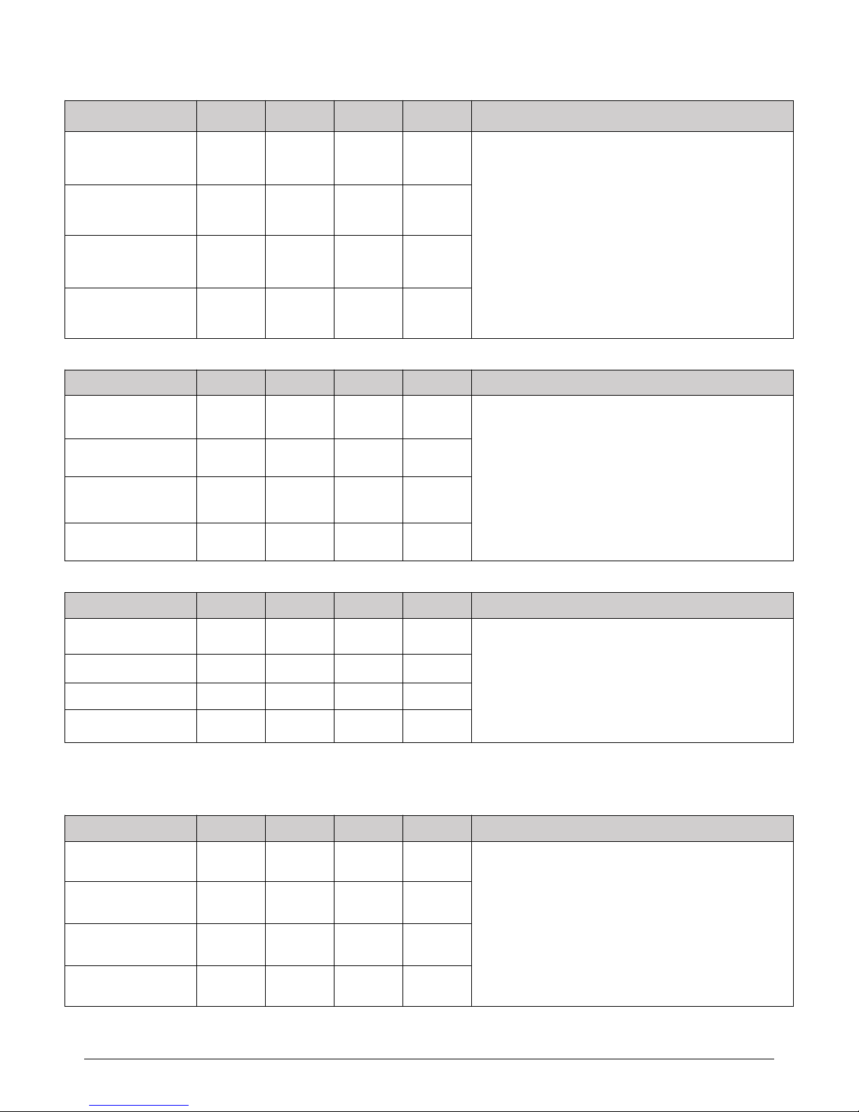
1.2.1. Transmitting current
Model
Min
Typ
Max
Unit
Remarks
E18-MS1-PCB
25.8
28.0
30.8
mA
● When designing current supply circuit, 30% margin is
recommended to be remained so as to ensure long-term
stable operation of the whole module;
● The current at the instant of transmitting may be high,
but the total energy consumed may be lower due to very
short transmitting time;
● When using external antenna, the impedance matching
degree at different frequency points between antenna
and module may affect the transmitting current value at
different levels.
E18-MS1-IPX
25.8
28.0
30.8
mA
E18-MS1PA1-PCB
128.8
140.0
154
mA
E18-MS1PA1-IPX
128.8
140.0
154
mA
1.2.2. Receiving current
Model
Min
Typ
Max
Unit
Remarks
E18-MS1-PCB
24.8
27.0
29.7
mA
● The current consumed when the RF chip is only working
at receiving mode is called as receiving current,the tested
receiving current may be higher for some RF chips with
communication protocol or the developers have loaded
their own protocol to the whole module.
● The current at pure receiving mode will be mA level, the
users have to realize µA level receiving current through
firmware development.
E18-MS1-IPX
24.8
27.0
29.7
mA
E18-MS1PA1-PCB
38.6
42.0
46.2
mA
E18-MS1PA1-IPX
38.6
42.0
46.2
mA
1.2.3. Turn-off current
Model
Min
Typ
Max
Unit
Remarks
E18-MS1-PCB
0.6
1.2
1.8
µA
● The turn-off current means the current consumed when
CPU, RAM, Clock and some registers remain operating while
SoC is at very low power consumption status.
● The turn-off current is always lower than the current
consumed when the power supply source of the whole
module is at no-load status.
E18-MS1-IPX
0.6
1.2
1.8
µA
E18-MS1PA1-PCB
0.6
1.2
1.8
µA
E18-MS1PA1-IPX
0.6
1.2
1.8
µA
1.2.4. Voltage supply
Model
Min
Typ
Max
Unit
Remarks
E18-MS1-PCB
2.0
3.3
3.6
V DC
● If the voltage is at maximum value for long time, the
module may be damaged;
● The power supply pin has certain surge-resistance ability,
but the potential pulse higher than the maximum power
supply voltage;
● The power supply voltage is recommended to be higher
than 3.0V, if the voltage is lower than 3.0V, the RF
parameters will be affected at different degrees.
E18-MS1-IPX
2.0
3.3
3.6
V DC
E18-MS1PA1-PCB
2.0
3.3
3.6
V DC
E18-MS1PA1-IPX
2.0
3.3
3.6
V DC
Page 5

CC2530 Wireless Module User Manual of E18 Series Modules
Copyright ©2012–2017, Chengdu Ebyte Electronic Technology Co., Ltd. 5 / 15
1.2.5. Communication level
Model
Min
Typ
Max
Unit
Remarks
E18-MS1-PCB
2.0
3.3
3.6
V DC
● If the communication level is higher than the allowed
maximum value, the module may be damaged;
● Although the communication level can be switched with
various methods, the power consumption of the whole
module will be affected at great degree.
E18-MS1-IPX
2.0
3.3
3.6
V DC
E18-MS1PA1-PCB
2.0
3.3
3.6
V DC
E18-MS1PA1-IPX
2.0
3.3
3.6
V DC
1.3. RF parameters
1.3.1. Transmitting power
Model
Min
Typ
Max
Unit
Remarks
E18-MS1-PCB
9.8
4.0
4.6
dBm
● Due to the error of the materials, each LRC component
has ±0.1% error, so error accumulation will occur since
multiple LRC components are used in the whole RF circuit,
and the transmitting currents will be different at different
modules;
● The power consumption can be lowered by lowering
the transmitting power, but the efficiency of the internal PA
will be decreased by lowering transmitting power due to
various reasons;
● The transmitting power will be lowered by lowering the
power supply voltage.
E18-MS1-IPX
9.8
4.0
4.6
dBm
E18-MS1PA1-PCB
9.8
20.0
21.2
dBm
E18-MS1PA1-IPX
9.6
20.0
20.5
dBm
1.3.2. Receiving sensitivity
Model
Min
Typ
Max
Unit
Remarks
E18-MS1-PCB
-95.8
-96.4
-97.0
dBm
● The sensitivity is tested under the air data rate of
250kbps;
● Due to the error of the materials, each LRC component
has ±0.1% error, so error accumulation will occur since
multiple LRC components are used in the whole RF circuit,
and the transmitting currents will be different at different
modules;
● The receiving sensitivity will be reduced and
communication range will be shortened while increasing the
air data rate.
E18-MS1-IPX
-95.8
-96.4
-97.0
dBm
E18-MS1PA1-PCB
-97.3
-97.6
-98.0
dBm
E18-MS1PA1-IPX
-97.3
-97.6
-98.0
dBm
1.4. Tested parameters
1.4.1. Tested distance
Model
Min
Typ
Max
Unit
Remarks
E18-MS1-PCB
180
200
230
m
● The external antenna used is of 5dBi gain and vertical
polarization;
● The interval between each data packet is 2s, sending 100
packets with 30 bytes in each packet, the range at data lose
rate of lower than 5% is valid range;
● In order to obtain meaningful and reproduceable results,
we conducted the tests under in clear weather with little
electromagnetic interference at suburb areas;
● Distance may be shorter with interference or obstacles.
E18-MS1-IPX
220
240
260
m
E18-MS1PA1-PCB
960
800
1220
m
E18-MS1PA1-IPX
540
1000
670
m
Page 6

CC2530 Wireless Module User Manual of E18 Series Modules
Copyright ©2012–2017, Chengdu Ebyte Electronic Technology Co., Ltd. 6 / 15
2. Mechanical characteristics
2.1. E18-MS1-PCB
Pin No.
Pin item
Pin direction
Application
1
GND
Input
Ground, connecting to power source referential ground
2
VDD
Input
Power supply, must be 2.0 ~ 3.6V
3
P2.2
Input/Output
MCU GPIO
4
P2.1
Input/Output
MCU GPIO
5
P2.0
Input/Output
MCU GPIO
6
P1.7
Input/Output
MCU GPIO
7
P1.6
Input/Output
MCU GPIO
8
NC
Reserved
9
NC
Reserved
10
P1.5
Input/Output
MCU GPIO
11
P1.4
Input/Output
MCU GPIO
12
P1.3
Input/Output
MCU GPIO
13
P1.2
Input/Output
MCU GPIO
14
P1.1
Input/Output
MCU GPIO
15
P1.0
Input/Output
MCU GPIO
16
P0.7
Input/Output
MCU GPIO
17
P0.6
Input/Output
MCU GPIO
18
P0.5
Input/Output
MCU GPIO
19
P0.4
Input/Output
MCU GPIO
20
P0.3
Input/Output
MCU GPIO
21
P0.2
Input/Output
MCU GPIO
22
P0.1
Input/Output
MCU GPIO
23
P0.0
Input/Output
MCU GPIO
24
RESET
Input
Reset port
★ Please refer to TI official CC2530 Datasheet for module pin definitions, software driver and protocol ★
Page 7

CC2530 Wireless Module User Manual of E18 Series Modules
Copyright ©2012–2017, Chengdu Ebyte Electronic Technology Co., Ltd. 7 / 15
2.2. E18-MS1-IPX
Pin No.
Pin item
Pin direction
Application
1
GND
Ground, connecting to power source referential ground
2
VDD
Power supply, must be 2.0 ~ 3.6V
3
P2.2
Input/Output
MCU GPIO
4
P2.1
Input/Output
MCU GPIO
5
P2.0
Input/Output
MCU GPIO
6
P1.7
Input/Output
MCU GPIO
7
P1.6
Input/Output
MCU GPIO
8
NC
Reserved
9
NC
Reserved
10
P1.5
Input/Output
MCU GPIO
11
P1.4
Input/Output
MCU GPIO
12
P1.3
Input/Output
MCU GPIO
13
P1.2
Input/Output
MCU GPIO
14
P1.1
Input/Output
MCU GPIO
15
P1.0
Input/Output
MCU GPIO
16
P0.7
Input/Output
MCU GPIO
17
P0.6
Input/Output
MCU GPIO
18
P0.5
Input/Output
MCU GPIO
19
P0.4
Input/Output
MCU GPIO
20
P0.3
Input/Output
MCU GPIO
21
P0.2
Input/Output
MCU GPIO
22
P0.1
Input/Output
MCU GPIO
23
P0.0
Input/Output
MCU GPIO
24
RESET
Input
Reset port
★ Please refer to TI official CC2530 Datasheet for module pin definitions, software driver and protocol ★
Page 8

CC2530 Wireless Module User Manual of E18 Series Modules
Copyright ©2012–2017, Chengdu Ebyte Electronic Technology Co., Ltd. 8 / 15
2.3. E18-MS1PA1-PCB
Pin No.
Pin item
Pin direction
Application
1
GND
Input
Ground, connecting to power source referential ground
2
VCC
Input
Power supply, must be 2.0 ~ 3.6V
3
P2.2
Input/Output
MCU GPIO
4
P2.1
Input/Output
MCU GPIO
5
P2.0
Input/Output
MCU GPIO
6
P1.7
Input/Output
MCU GPIO
7
P1.6
Input/Output
MCU GPIO
8
NC
Reserved
9
NC
Reserved
10
P1.5
Input/Output
MCU GPIO
11
P1.4
Input/Output
MCU GPIO
12
P1.3
Input/Output
MCU GPIO
13
P1.2
Input/Output
MCU GPIO
14
P1.1
Output
MCU GPIO, PA transmitting control pin
15
P1.0
Output
MCU GPIO, PA receiving control pin
16
P0.7
Output
MCU GPIO, PA receiving high gain control pin
17
P0.6
Input/Output
MCU GPIO
18
P0.5
Input/Output
MCU GPIO
19
P0.4
Input/Output
MCU GPIO
20
P0.3
Input/Output
MCU GPIO
21
P0.2
Input/Output
MCU GPIO
22
P0.1
Input/Output
MCU GPIO
23
P0.0
Input/Output
MCU GPIO
24
RESET
Input
Reset port
★ Please refer to TI official CC2530 Datasheet for module pin definitions, software driver and protocol ★
Page 9

CC2530 Wireless Module User Manual of E18 Series Modules
Copyright ©2012–2017, Chengdu Ebyte Electronic Technology Co., Ltd. 9 / 15
2.4. E18-MS1PAI-IPX
Pin No.
Pin item
Pin direction
Application
1
GND
Input
Ground, connecting to power source referential ground
2
VCC
Input
Power supply, must be 2.0 ~ 3.6V
3
P2.2
Input/Output
MCU GPIO
4
P2.1
Input/Output
MCU GPIO
5
P2.0
Input/Output
MCU GPIO
6
P1.7
Input/Output
MCU GPIO
7
P1.6
Input/Output
MCU GPIO
8
NC
Reserved
9
NC
Reserved
10
P1.5
Input/Output
MCU GPIO
11
P1.4
Input/Output
MCU GPIO
12
P1.3
Input/Output
MCU GPIO
13
P1.2
Input/Output
MCU GPIO
14
P1.1
Output
MCU GPIO, PA transmitting control pin
15
P1.0
Output
MCU GPIO, PA receiving control pin
16
P0.7
Output
MCU GPIO, PA receiving high gain control pin
17
P0.6
Input/Output
MCU GPIO
18
P0.5
Input/Output
MCU GPIO
19
P0.4
Input/Output
MCU GPIO
20
P0.3
Input/Output
MCU GPIO
21
P0.2
Input/Output
MCU GPIO
22
P0.1
Input/Output
MCU GPIO
23
P0.0
Input/Output
MCU GPIO
24
RESET
Input
Reset port
★ Please refer to TI official CC2530 Datasheet for module pin definitions, software driver and protocol ★
Page 10

CC2530 Wireless Module User Manual of E18 Series Modules
Copyright ©2012–2017, Chengdu Ebyte Electronic Technology Co., Ltd. 10 / 15
3. Usage
3.1. Development
No.
Keyword
Remark
1
Programming
Embedded 8051 MCU, Program-download can only use specified downloader CC-DeBu
gger,, UART or any other tools like JTAG、ISP、ICP cannot be used for download.
Demo program can be provided for user as reference. User can download the compiled HEX
file directly, or modify on the basis of primary code to achieve their needs.
2
Test board
N/A
Below function available for PA version module
No.
Keyword
Remark
1
Burn firmware
The module is with built-in 8051 MCU,to download program please use downloader YHT15-A2(click
to open)
Page 11

CC2530 Wireless Module User Manual of E18 Series Modules
Copyright ©2012–2017, Chengdu Ebyte Electronic Technology Co., Ltd. 11 / 15
2
Initiate PA
Initiate PA , modify it in file hal_board_cfg.h.
3
Parameter
setting
The setting of CC2592 in zstack,CC2530 pin: P1.1、P1.0、P0.7 are connected with CC2592 pin :PA_EN、
LNA_EN、HGM. Meanwhile, LNA_EN is in high level,and it is in receiving mode.
4
Program
modification
Find macRadioTurnOnPower() from mac_radio_defs.c,and modify.
5
Power
modification
Find static CODE const macPib_t macPibDefaults from file mac_pib.c. Modify in the red signed below.
Page 12

CC2530 Wireless Module User Manual of E18 Series Modules
Copyright ©2012–2017, Chengdu Ebyte Electronic Technology Co., Ltd. 12 / 15
4. Programming
You are recommended to use the Code Composer Studio (CCS) integrated development environment (IDE) applicable for wireless.
Code Composer Studio is a kind of IDE, it supports TI MCU and embedded processor series products. Code Composer Studio covers a
whole set of tools for development and embedded application. It covers the C/C++ compiler for optimizing, source code editor, project
building environment, debugger, descriptor and many other functions. The IDE provides individual user interface, it can help you complete
every step in developing. Familiar tool and interface enables users to start more quickly. Code Composer Studio integrates the advantages
of Eclipse software frame and the embedded debugging function of TI and provides a knockout and functionable development
environment.
4.1. TI ZigBee FAQ
4.1.1. How to select proper protocol stack from different ZigBee protocol stacks of TI?
From the Z-Stack 0.1 to Z-Stack 2.5.1a and the current Z-Stack Home 1.2.1, Z-Stack Lighting 1.0.2, Z-Stack Energy 1.0.1, Z-Stack Mesh 1.0.0,
TI mainly upgraded the protocol stack through: 1) adding some new features according to ZigBee Specification of the ZigBee Alliance, for
example, ZigBee2007 tree-shape route, adding Mesh route in ZigBee Pro, and raising MTO and Source Routing algorithms so TI added
some new functions to the protocol stack, also did some correction of bugs in Spec such as some unclear descriptions; 2) Correction of
bugs of TI ZigBee protocol itself. You can find the differences between one protocol stack and the previous version in the Release Note of
the installation directory.
After the Z-Stack 2.5.1a, TI did not publish the protocol stack in the form of Z-Stack 2.6.x but in Application Profile form, because TI hopes
the developers could select proper protocol stack based on actual applications. The protocol stacks like Z-Stack Home 1.2.1 includes two
parts: 1)Core Stack, it is the follow-up versions of Z-Stack 2.5.1a, it can be found from the Z-Stack Core Release Notes.txt, Version 2.6.2. 2)
Profile-related part, this part is related to the actual application, Home Automation stack is about the realization of ZigBee Home
Automation Profile. Meanwhile, Z-Stack Lighting 1.0.2 and Z-Stack Energy 1.0.1 are Core Stack with Profile for application.
1) Z-Stack Home 1.2.2a is specific for smart home products development.
2) Z-Stack Lighting 1.0.2 is specific for ZLL products development.
3) Z-Stack Energy 1.0.1 is specific for intelligent energy, meter, In Home Display, and so on.
4) Z-Stack Mesh 1.0.0 is specific for private applications, it only utilizes the function of standard ZigBee protocol, Mesh route and so on,
the application layer shall be defined by the developer.
After the publish of ZigBee 3.0 protocol, the latest ZigBee protocol stack is Z-Stack 3.0, it supports CC2530 and CC2538.
4.1.2. How to apply for standard ZigBee test certification?
Take standard ZigBee Home Automation products as example, developers must develop according to the description in the ZigBee Home
Automation Profile Specification, this document can be found from www.zigbee.or. After developing the product, developers need to
learn the ZigBee Home Automation Profile Test Specification, this document described the items to be tested by the Test House, it can be
downloaded from www.zigbee.org also, in addition, there is another PICS document, it is specific for describing the functions supported,
developers confirm the functions by checking the boxes according to the actual functions and the required functions in the Specification,
as below are the testing procedure:
1) Join the ZigBee alliance, generally assisted by testing labs;
2) Send samples to testing lab, complete the PICS file;
3) First round pre-testing, the testing lab feedback the testing results, developers modify the sample codes.
4) The testing lab verify the modified sample, and starts formal test;
5) The testing lab assists developers to complete the ZigBee alliance online certification application;
6) The testing lab submits the test report to ZigBee alliance. The alliance will review and issue certificate.
Currently, there are two testing labs in China who can complete standard ZigBee test:
1) CESI in Beijing;
2) Element Shenzhen Office (headquartered in England)
Please refer to below wiki link for details:
http://processors.wiki.ti.com/index.php/ZigBee_Product_Certification_Guide
Page 13

CC2530 Wireless Module User Manual of E18 Series Modules
Copyright ©2012–2017, Chengdu Ebyte Electronic Technology Co., Ltd. 13 / 15
How to select the 64-bit MAC address of the device?
There are two IEEE addresses in CC2530/CC2538/CC2630, one is Primary IEEE address, the other is Secondary address. Primary IEEE
address is stored in Information Page of the chip, this address is bought by TI from IEEE, each chip has one unique address. Users could
only Read this value and cannot modify or erase it. By reading the address in the protocol stack, users can obtain
osal_memcpy(aExtendedAddress, (uint8 *)(P_INFOPAGE+HAL_INFOP_IEEE_OSET), Z_EXTADDR_LEN). Secondary address is stored in the
last Page of the Flash of CC2530, users can Read/Write with the function HalFlashRead(HAL_FLASH_IEEE_PAGE, HAL_FLASH_IEEE_OSET,
aExtendedAddress, Z_EXTADDR_LEN).
When the protocol stack is operating, how to select Primary IEEE address or Secondary address as MAC address? Please operate in the
function zmain_ext_addr(void).
1) Read IEEE address from NV, if it already exists (not 0xFF), use this address as MAC address;
2) If not in 1), read from the Secondary IEEE address storage place, if it exists (not 0xFF), write the address into NV, and use this address
as MAC address;
3) If not in 2), read from the Primary IEEE address storage place, if it exists (not 0xFF), write the address into NV, and use this address as
MAC address;
4) If not in 3), generate one 64-bit variable randomly, write it into NV, use it as MAC address.
4.1.3. How to forbid node from searching network, or extend the interval for sending Beacon Request?
End Device is low power consumption device powered by battery, after cutting from network, how to forbid the node from searching
network, or how to extend the interval for sending Beacon Request.
1) Start searching network uint8 ZDApp_StartJoiningCycle(void)
Stop searching network uint8 ZDApp_StopJoiningCycle(void)
2) Change the Beacon Request sending period
Modify the variable zgDefaultStartingScanDuration
// Beacon Order Values
#define BEACON_ORDER_NO_BEACONS 15
#define BEACON_ORDER_4_MINUTES 14 // 245760 milliseconds
#define BEACON_ORDER_2_MINUTES 13 // 122880 milliseconds
#define BEACON_ORDER_1_MINUTE 12 // 61440 milliseconds
#define BEACON_ORDER_31_SECONDS 11 // 30720 milliseconds
#define BEACON_ORDER_15_SECONDS 10 // 15360 MSecs
#define BEACON_ORDER_7_5_SECONDS 9 // 7680 MSecs
#define BEACON_ORDER_4_SECONDS 8 // 3840 MSecs
#define BEACON_ORDER_2_SECONDS 7 // 1920 MSecs
#define BEACON_ORDER_1_SECOND 6 // 960 MSecs
#define BEACON_ORDER_480_MSEC 5
#define BEACON_ORDER_240_MSEC 4
#define BEACON_ORDER_120_MSEC 3
#define BEACON_ORDER_60_MSEC 2
#define BEACON_ORDER_30_MSEC 1
#define BEACON_ORDER_15_MSEC 0
4.1.4. How to put End Device into low power consumption mode, how to set up sleep time?
After the POWER_SAVING is enabled in the protocol stack macro definition, put DRFD_RCVC_ALWAYS_ON=FALSE in f8wConfig.cfg file,
then the End Device will enter sleep mode.
The sleep time is decided by the OSAL operating system, the latest Event Timeout to occur will be set as sleep time. There is description in
the protocol stack hal_sleep function.
There are two kinds of timeout: one is the timeout of application layer event, the other is the timeout of MAC layer event.
1) Timeout of application layer, can be obtained through osal_next_timeout() of osal_pwrmgr_powerconserve(void) function;
2) Timeout of MAC layer, can be obtained through MAC_PwrNextTimeout() of halSleep(uint16 osal_timeout) function.
4.1.5. What new features does ZigBee 3.0 stack have?
Please refer to below link, it describes the new features of the ZigBee 3.0 stack as compared with the previous ZigBee Home
Automation/ZigBee Light Link.
http://processors.wiki.ti.com/index.php/What%27s_New_in_ZigBee_3.0
About the status switch in the TI ZigBee protocol stack
http://www.deyisupport.com/question_answer/wireless_connectivity/zigbee/f/104/t/104629.aspx
Page 14

CC2530 Wireless Module User Manual of E18 Series Modules
Copyright ©2012–2017, Chengdu Ebyte Electronic Technology Co., Ltd. 14 / 15
4.1.6. About the difference between OAD and OTA in TI protocol stack?
OAD is short for Over the Air Download, OTA is short for Over the Air. The functions of these two are the same, they can be called the
software upgrade on air. In the earlier ZigBee protocol standard, there was no standard for node software upgrading on air, but many
customers have such requirements, thus TI developed their own protocol stack for software upgrading on air, and named it as OAD. After
that, ZigBee alliance noticed the more and more requirements for upgrading on air, so they developed the upgrading on air standard and
named it as OTA, this standard has taken the TI OAD method as reference and has made some modification. The upgrading on air in TI’s
earlier protocol stack, it is called OAD, and in the later stack, it is called OTA as following the ZigBee alliance stack.
4.1.7. Which protocol stack shall be selected for developing private application based on ZigBee Mesh?
Many customers only need to apply the function of ZigBee Mesh network in their system or products, and do not need to do according to
the application layer as defined by the ZigBee, especially for some industrial applications, as for such requirements, how to select proper TI
protocol stack for developing products?
http://www.deyisupport.com/question_answer/wireless_connectivity/zigbee/f/104/t/132197.aspx
5. Production guidance
5.1. Reflow soldering temperature
Pre-heating area: maximum temperature rise is 2.5℃/s;
Thermal insulation area: temperature is 150~190℃, time is 60~90s,maximum temperature rise is 2.5℃/s;
Reflowing area: maximum temperature is 235~245℃, time for above 217℃ is 40~80s;
Cooling area: maximum temperature drop is 4℃/s.
5.2. Reflow soldering curve
Page 15

CC2530 Wireless Module User Manual of E18 Series Modules
Copyright ©2012–2017, Chengdu Ebyte Electronic Technology Co., Ltd. 15 / 15
6. FAQ
6.1. Communication range is too short
The communication distance will be affected when obstacle exists.
Data lose rate will be affected by temperature, humidity and co-channel interference.
The ground will absorb and reflect wireless radio wave, so the performance will be poor when testing near ground.
Sea water has great ability in absorbing wireless radio wave, so performance will be poor when testing near the sea.
The signal will be affected when the antenna is near metal object or put in a metal case.
Power register was set incorrectly, air data rate is set as too high (the higher the air data rate, the shorter the distance).
The power supply low voltage under room temperature is lower than 2.5V, the lower the voltage, the lower the transmitting power.
Due to antenna quality or poor matching between antenna and module.
6.2. Module is easy to damage
Please check the power supply source, ensure it is 2.0V~3.6V, voltage higher than 3.6V will damage the module.
Please check the stability of power source, the voltage cannot fluctuate too much.
Please make sure antistatic measure are taken when installing and using, high frequency devices have electrostatic susceptibility.
Please ensure the humidity is within limited range, some parts are sensitive to humidity.
Please avoid using modules under too high or too low temperature.
7. Important Notes
All rights to interpret and modify this manual belong to Ebyte.
This manual will be updated based on the upgrade of firmware and hardware, please refer to the latest version.
Please refer to our website for new product information.
8. About us
Technical support: support@cdebyte.com
Documents and RF Setting download link: www.cdebyte.com/en/
Tel:+86-28-61399028
Fax:028-64146160
Web:www.cdebyte.com/en/
Address:Innovation Center D347, 4# XI-XIN Road,Chengdu, Sichuan, China
 Loading...