

Page 1
E34-DTU (2G4H20)
Page 2

Chengdu Ebyte Electronic Technology Co.,Ltd. E34-DTU (2G4H20) user manual
Copyright ©2012–2019,Chengdu Ebyte Electronic Technology Co,;Ltd 1
Content
1.Introduction............................................................................................................................................ 2
1.1.Brief Introduction .......................................................................................................................... 2
1.2.Features........................................................................................................................................ 2
2.Operation ................................................................ ............................................................................... 3
3.Installation Specifications................................................................................................ ......................... 5
3.1.Structure....................................................................................................................................... 5
3.2.Dimension .................................................................................................................................... 6
4.Interface Defination................................................................................................................................. 7
4.1.Power interface definition ................................................................ ............................................... 7
4.2.RS232 Interface definition .............................................................................................................. 7
4.3.RS485 Interface definition .............................................................................................................. 7
5. Technical indicators ............................................................................................................................ 8
5.1.Model specifications ...................................................................................................................... 8
5.2.General specification parameters ..................................................................................................... 8
5.3.Frequency range and channels ......................................................................................................... 8
5.4.Transmit power level................................................................ ...................................................... 9
5.5.Current parameters ........................................................................................................................ 9
5.6.Transceiver Length and Sub-packing Mode....................................................................................... 9
6.Operating mode ...................................................................................................................................... 9
7.Connection diagram when programming .................................................................................................. 10
7.1.diagrammatic drawing .................................................................................................................. 10
7.2.Parameter setting instruction ................................................................ ..........................................11
8.Connection diagram in test and application ................................ ............................................................... 12
9.E32-DTU series .................................................................................................................................... 13
10.Practical application................................................................ ............................................................. 13
11.Note................................................................ ................................................................................... 14
12.Important statement ............................................................................................................................. 15
Page 3

Chengdu Ebyte Electronic Technology Co.,Ltd. E34-DTU (2G4H20) user manual
Copyright ©2012–2019,Chengdu Ebyte Electronic Technology Co,;Ltd 2
1.Introduction
1.1. Brief Introduction
E34-DTU (2G4H20) is a full duplex wireless data transmission module for point-to-point transmission( Has both
RS232 and RS485), transmission power is 100mW, transparent transmission mode, working in 2400MHz band
high-performance 2.4g wireless module, UART serial port interface, transparent transmission, at the same time support
3.3v or 5.0v system, packet loss automatic retransmission, support automatic frequency hopping, anti-interference ability
is very strong.
E34-DTU (2G4H20) in order to ensure the secrecy and anti-interference of communication, compared with
fixed-frequency communication, frequency-hopping communication is more covert and difficult to be intercepted.
Support address function, host can transmit data to any address of any channel module, network relay and ot her
applications; The air speed is high, so the transmission speed is fast, the delay is small and the data throughput is large. It
is especially suitable for applications requiring small delay and large data volume, such as real-time remote control with
good anti-interference ability. Even if some frequency points are interfered, it can still carry out normal communication
on other frequency points that are not interfered, and it has been mass produced and widely used in related industries
E34-DTU (2G4H20) is Strictly abided by domestic and foreign design specifications such as FCC CE and CCC,
meet various rf related certification, and meet export requirements
1.2. Features
★ All core components are originally imported; our transceiver modems have much advanced functions with smaller size
and lower cost.
★ The top TX power is 100mW, all technical parameters meet European industrial standards.
★ Temperature compensators are adopted to make the frequency stability better than ±1.5PPM.
★ Operation temperature range: -40℃~+85℃, applicab le for various harsh environment, it is real industrial grade
products.
★ Aluminum alloy case, compact size, great heat dispersion; good shielding, prime electromagnetic compatibility and
strong anti-interference.
★ Power reverse & overload protection and antenna surge protection functions significantly improve the reliability.
★ Parameters can be configured by programming, such as TX power, frequency point, air data rate, address and so on.
★ Ultra-low power consumption, standby current is only 25.5mA (even lower under power -saving and sleep modes), TX
current ≤0.14A .
★ Embedded watch-dog and precise time layout, modem will restart automatically upon abnormal situation and work
with previous parameters.
★ The transceivers adopt original nRF24L01P+ chip, customers highly comment the products because of the super
reliability.
Page 4
Chengdu Ebyte Electronic Technology Co.,Ltd. E34-DTU (2G4H20) user manual
Copyright ©2012–2019,Chengdu Ebyte Electronic Technology Co,;Ltd 3
2. Operation
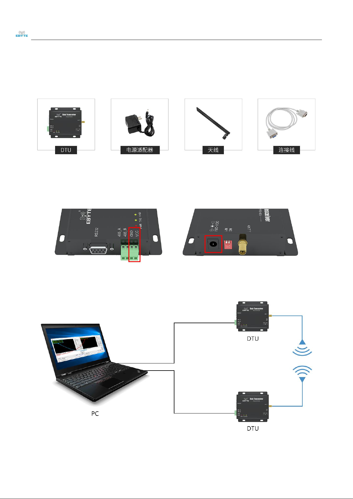
Main parts
1、 First step is to mount antenna, then battery, making sure the dial switch is on its right status. User gets on the power
by choosing either VCC/GND or power adapter.
2、 Using USB-(RS232) converter or USB-RS(485) converter or other way to link computer and DTU.
Page 5
Chengdu Ebyte Electronic Technology Co.,Ltd. E34-DTU (2G4H20) user manual
Copyright ©2012–2019,Chengdu Ebyte Electronic Technology Co,;Ltd 4
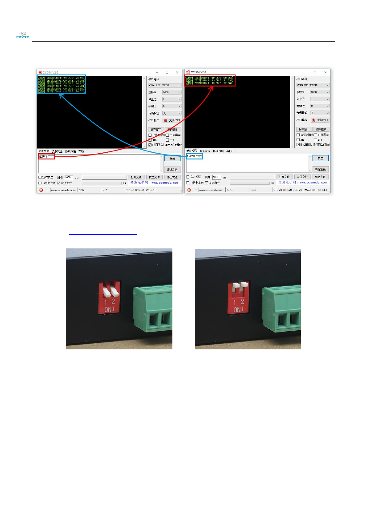
3、 Firing up two XCOMs, choosing Baud rate 9600bps, 8N1, the setting which serial port transmission can be
achieved.
4、 User needs to open the mode switch first before link DTU with computer if the user want to modify parameters.
Firing up E34-DTU 数传电台配置软件 (E34-DTU parameter configuration application) to modify related parameters.
The mode switch must be reopened to achieve transmission after the configuration.
Mode 0 Default Mode 3 Parameter setting
Page 6
Chengdu Ebyte Electronic Technology Co.,Ltd. E34-DTU (2G4H20) user manual
Copyright ©2012–2019,Chengdu Ebyte Electronic Technology Co,;Ltd 5
3. Installation Specifications
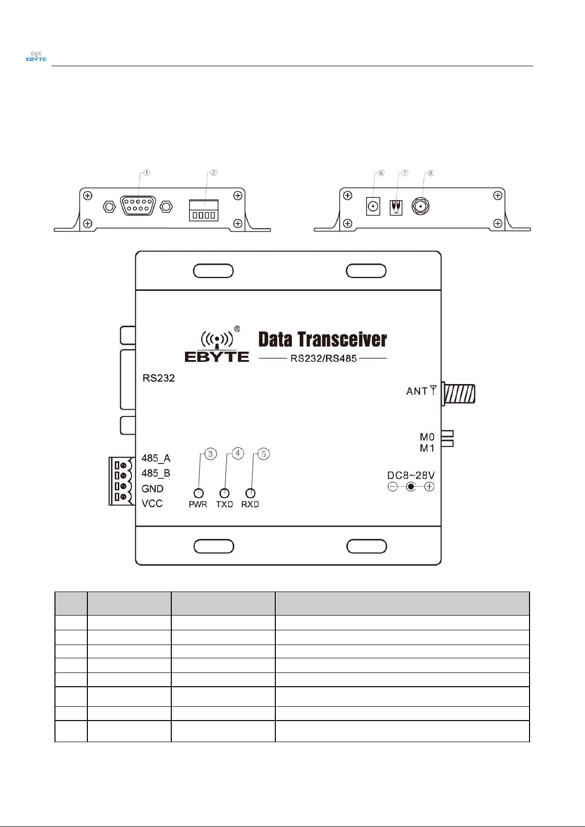
3.1. Structure
Pin
NO.
Name
Function
Description
1
DB-9 female socket
RS-232 interface
Standard RS-232 interface
2
3.81 terminal block
RS-485, power interface
Standard RS-485 interface and pressure line power interface
3
PWR-LED
Power LED
Red, lit when the power is on
4
TXD-LED
Transmit LED
Yellow, blinks when sending data
5
RXD-LED
Receive LED
Yellow, blinks when receiving data
6
DC power interface
Power interface
In-line round hole, outer diameter 5.5mm, diameter 2.5mm
7
DIP switch
DIP switch
Controlled by working mode
8
Antenna interface
SMA-K interface
external thread, 10mm, 50Ωcharacteristic impedance
Page 7

Chengdu Ebyte Electronic Technology Co.,Ltd. E34-DTU (2G4H20) user manual
Copyright ©2012–2019,Chengdu Ebyte Electronic Technology Co,;Ltd 6
3.2. Dimension
Unit:mm
Page 8

Chengdu Ebyte Electronic Technology Co.,Ltd. E34-DTU (2G4H20) user manual
Copyright ©2012–2019,Chengdu Ebyte Electronic Technology Co,;Ltd 7
4. Interface Defination
4.1. Power interface definition
Users can choose ⑥ DC power interface, using the power adapter supply with the interface of the 5.5mm outer
diameter , 2.5mm diameter ;
Also choose the VCC and GND terminal power supply, only choose any one of the power supply is OK;
E34-DTU can use 10~ 28V DC power supply, but it is recommended to use 12V or 24V DC power supply.
4.2. RS232 Interface definition
The E34-DTU can be connected to the device via RS-232 using the standard DB-9 interface.
4.3. RS485 Interface definition
E34-DTU can connect the 485_A terminal and 485_B terminal with the device RS-485 A terminal and B terminal.
★
Pin NO.
Definition
Function
Description
1
VCC
Crimping power interface, positive
10~ 28V DC, recommended 12V or 24V
2
GND
Crimping power interface, negative
The power supply negative pole is connected to the system
ground and the housing
3
485_B
RS-485 interface, interface B
The RS-485 interface B is connected to the device interface B
4
485_A
RS-485 interface, interface A
The RS-485 interface A is connected to the device interface A
Page 9

Chengdu Ebyte Electronic Technology Co.,Ltd. E34-DTU (2G4H20) user manual
Copyright ©2012–2019,Chengdu Ebyte Electronic Technology Co,;Ltd 8
★ Note: The transceiver will be in poor communication when connected to multiple devices, it is recommended to be
connected to a single device, please try to use parallel 120Ω resistor between 485_A terminal and 485_B.
5. Technical indicators
5.1. Model specifications
Model
Frequenc
y
Transmit
power
Distance
Specifications
Application
Hz W km
E34-DTU(2G4H20)
2400
0.1
2
Automatic frequency
hopping, automatic packet
loss retransmission
Suitable for open environment
with few obstacles
★ Note: Test condition: in clear and open air without shelters, 12V /2A power supply, 5dBi gain sucker antenna over 2
meters height from the ground, with the factory default parameters.
5.2. General specification parameters
NO.
Model
Specification
Description
1
Size(H*W*D)
82 * 62 * 25mm
See more at 3.2 Dimension
2
Weight
131g
Tolerance: 4.5g
3
Temperature
-40℃~85℃
Meet industrial level
4
Antenna impedance
50 Ω
Standard 50 Ω characteristic impedance
5
Supply voltage
+10 ~ +28V DC
It is recommended to use 12V or 24V
6
Communication interface
RS232/RS485
Standard DB9 hole / 3.81 terminal block
7
Baud rate
Default 9600
from 1200 to 115200 bps
8
Address
Default 0
65536 configurable addresses
5.3. Frequency range and channels
Model
Default frequency
Frequency range
Channel
spacing
Channels
Hz
Hz
Hz
E34-DTU(2G4H20)
2400 MHz
2400 ~ 2518 MHz
MHz
Half-duplex
★ Note: In the same area when multiple data transceivers are communicating one to one at the same time, it is
recommended to set the channel spacing between each group of data transceivers at 2MHz or more.
Page 10

Chengdu Ebyte Electronic Technology Co.,Ltd. E34-DTU (2G4H20) user manual
Copyright ©2012–2019,Chengdu Ebyte Electronic Technology Co,;Ltd 9
5.4. Transmit power level
Mode
1.3mW
5mW
25mW
100mW
E34-DTU(2G4H20)
√ √ √
√
★ Note: The lower the transmit power, the closer the transmission distance, but the working current won’t be declined in
exact proportion, it is recommended to use the maximum transmit power.
5.5. Current parameters
Model
Transmitting current mA
Standby current mA
12V
24V
12V
24V
E34-DTU(2G4H20)
143
86
25.5
32
★ Note: It is recommended to retain more than 50% of the current margin when selecting the power supply, which w ill
help the data transceiver to work steadily for a long time.
5.6. Transceiver Length and Sub-packing Mode
Model
Buffer
Sub-package
E34-DTU(2G4H20)
256Byte
Automatic subcontracting of 27 bytes to send
★ Note:
1. When the receiving data is more than a single packet capacity, the beyond part will be automatically assigned
to the second transmission until it is completed;
2. The data transceiver cannot receive data which is more than the buffer capacity;
6. Operating mode
E34-DTU(2G4H20) has four operating modes, if low power consumption is not required, normal communication is
recommended to configure the data transceiver for the normal mode (mode 0);
The factory default is normal mode (mode 0).
Categories
M1
M0
Description
Mode 0
Normal Mode
ON
ON
Open UART and RF,transparent transmission is on
Mode 1
Wake-up Mode
ON
OFF
Air wake-up mode, the packet comes with a wake-up code,
Mode 2
Power-saving Mode
OFF
ON
The air wake-up receive mode, saving receive power, the mode can not
be transmitted
Mode 3
Sleep Mode
OFF
OFF
Parameter setting using the configuration software
Page 11

Chengdu Ebyte Electronic Technology Co.,Ltd. E34-DTU (2G4H20) user manual
Copyright ©2012–2019,Chengdu Ebyte Electronic Technology Co,;Ltd 10
★ Note: no need to care about the wake-up mode (mode 1) and power saving mode (mode 2) if it doesn’t request low
power consumption.
7. Connection diagram when programming
7.1. diagrammatic drawing
Mode
M1
M0
Description
Mode 3
Sleep Mode
Off
Off
Only be programmed using the configuration software in the current mode
Page 12

Chengdu Ebyte Electronic Technology Co.,Ltd. E34-DTU (2G4H20) user manual
Copyright ©2012–2019,Chengdu Ebyte Electronic Technology Co,;Ltd 11
★ Note:
1.programming can only be carried on in a specific mode(see above), if fails, please confirm the work mode.
2.If there’s no complicated programming, opening the E34-DTU 数传电台配置软件 (E34-DTU parameter configuration
application) to modify parameters.
7.2. Parameter setting instruction
Parameter
Description
Baud rate
The serial port baud rate of a wireless data station at work,1200bps~115200bps。
Odd-even check
Support 8N1:no check ;8E1:even-check;8O1:odd-check;Both are 8-bit data bits and 1-bit stop
bits.
Air data rate(bps)
Wireless communication rate, also known as air baud rate air rate high, data transmission speed,
transmission of the same data time delay is small, but the transmission distance will become
shorter. 64kbps is the most recommended value
Page 13

Chengdu Ebyte Electronic Technology Co.,Ltd. E34-DTU (2G4H20) user manual
Copyright ©2012–2019,Chengdu Ebyte Electronic Technology Co,;Ltd 12
Transmitting power
In order to ensure the working efficiency, it is recommended to use the maximum power. If the
transmitted power is reduced, the communication distance will become shorter and the required
current will be reduced
FEC
The lost or interfered data can be partially corrected by complex encoding, which can improve
the equivalent receiving sensitivity by about 3dBm. Turning off this function can reduce the
communication delay.
Transmission mode
Transparent transmission, and send-as-received fixed points, broadcasting is not supported
Wake Up Time
There is no direct relationship with the communication delay. If the customer needs low-power
applications, this option shall be adjusted as required to ensure the communication stability.
This parameter is self-adaptive and needs no attention from the user.
IO driven
By default, select the internal TTL signal drive mode。
Station Address
Internal address of wireless data station, stations with the same address as those independent of
Modbus address can communicate with each other. This feature can be used to realize software
filtering grouping input range :0~65535, decimal number.
Frequency Channel
It is equivalent to the working frequency of wireless data transmission station. Each channel
corresponds to its different working frequency. Theoretically, different frequency channels
cannot communicate with each other.
8. Connection diagram in test and application
Page 14

Chengdu Ebyte Electronic Technology Co.,Ltd. E34-DTU (2G4H20) user manual
Copyright ©2012–2019,Chengdu Ebyte Electronic Technology Co,;Ltd 13
9. E32-DTU series
Mode No.
Interface
Frequency
Hz
Tx power
dBm
Distance
km
Function feature
E34-DTU(2G4H27)
RS232 RS485
2.4G
27
5
Automatic frequency hopping, automatic
packet loss retransmission
E34-DTU (2G4D20)
RS232 RS485
2.4G
20
2
Full duplex, two-way simultaneous
transmission.
E34-DTU (2G4H20)
RS232 RS485
2.4G
20
2.5
Automatic frequency hopping, automatic
packet loss retransmission
10. Practical application
The data transceiver of CDEBYTE is applied for all kinds of point to point, one point to multiple points wireless
data transmission system, such as smart home, Internet of things transformation, power load monitoring, distribution
network automation, hydrological and hydrological forecasting, water pipe network monitoring, urban street lamps
Monitoring, air defense alarm control, railway signal monitoring, centralized control of railway water supply, oil supply
pipe network monitoring, GPS system, remote meter reading, electronic crane, automatic reporting, seismic forecasting,
fire prevention, environmental monitoring and other industrial automation system, as shown below:
Page 15

Chengdu Ebyte Electronic Technology Co.,Ltd. E34-DTU (2G4H20) user manual
Copyright ©2012–2019,Chengdu Ebyte Electronic Technology Co,;Ltd 14
11.Note
1. Please keep the warranty card of the equipment which includes the factory number (and important technical
parameters) and is important for user's future maintenance and new equipment.
2. Transceiver during the warranty period, if the quality of the product itself rather than man-made damage or
lightning and other natural disasters caused by damage, enjoys free warranty; please do not repair by yourself, the
problem and please contact with our company when problem occurring, we offer the first -class after-sales service.
3. Please do not operate the transceiver in some flammable places such as coal mines or near explosive atmospheres
(such as detonators).
4. Please use the appropriate DC power supply, high frequency interference ability, small ripple, and enough load
capacity are required; it’s better to have over current, over voltage protection and lightning protection and other functions
to ensure that transceiver working properly.
5. Please do not use it in the working environment beyond the transceiver environmental characteristics , such as
high temperature, humidity, low temperature, strong electromagnetic fields or dust larger environment.
6. Please do not continuously keep transceiver to transmit in full capacity, or the transmitter might be damaged.
7. Please connect the ground with the external ground of the power supply (such as PC, PLC, etc.) , otherwise it is
easy to burn out the communication interface; do not plug the interface with power supplying.
8. When testing, please connect the antenna or 50 Ω load, otherwise transceiver will be damaged easily ;the distance
from the antenna is better than 2 meters, so as to avoid harm, please do not touch the antenna when transmitting.
9. Wireless data transceiver has different communication distance in different environments, communication
distance is influenced by temperature, humidity, obstacle density, obstacle volume and electromagnetic environment; in
order to ensure stable communication, it is recommended to reserve at least 50 % of the communication distance.
10. When communication distance is not perfect, it is recommended to improve the antenna quality and the
installation mode of the antenna. You can send mail to support@cdebyte.com for support.
11. When choosing power supply, it is recommended to keep at least 50% current left and the ripple must not exceed
100mV.
Page 16

Chengdu Ebyte Electronic Technology Co.,Ltd. E34-DTU (2G4H20) user manual
Copyright ©2012–2019,Chengdu Ebyte Electronic Technology Co,;Ltd 15
12.Important statement
1. CDEBYTE reserves the right of final interpretation and modification of all the contents of this manual.
2. As the hardware and software products continuously improving, this manual may subject to change without notice,
please refer to the latest version.
3. Everyone is responsible for protecting the environment: to reduce the use of paper, we only provide electronic
documents of the English manual, if necessary, please go to our official website to download; In addition, for special
requirements, we agree to offer certain amount of documents according to order quantity, not every data transceiver are
supplied with one manual, please understand;
Page 17

Chengdu Ebyte Electronic Technology Co.,Ltd. E34-DTU (2G4H20) user manual
Copyright ©2012–2019,Chengdu Ebyte Electronic Technology Co,;Ltd 16
Revision history
Version
Date
Description
Issued by
1.00
2018/8/30
Initial version
huaa
1.10
2019/4/2
M odel No. split
molly
About us
Technical support: support@cdebyte.com
Documents and RF Setting download link: www.ebyte.com
Thank you for using Ebyte products! Please contact us with any questions or suggestions: info@cdebyte.com
------------------------------------------------------------------------------------------------Fax: 028-64146160 ext. 821
Web: www.ebyte.com
Address: Innovation Center D347, 4# XI-XIN Road,Chengdu, Sichuan, China
 Loading...