

Page 1
UH Structures Inc. dba Ebtech Industrial
2241 Industrial Drive
Connellsville, PA 15425-6181
Telephone: 724-628-6100
Fax: 1-412-774-2429
www.ebtechindustrial.com
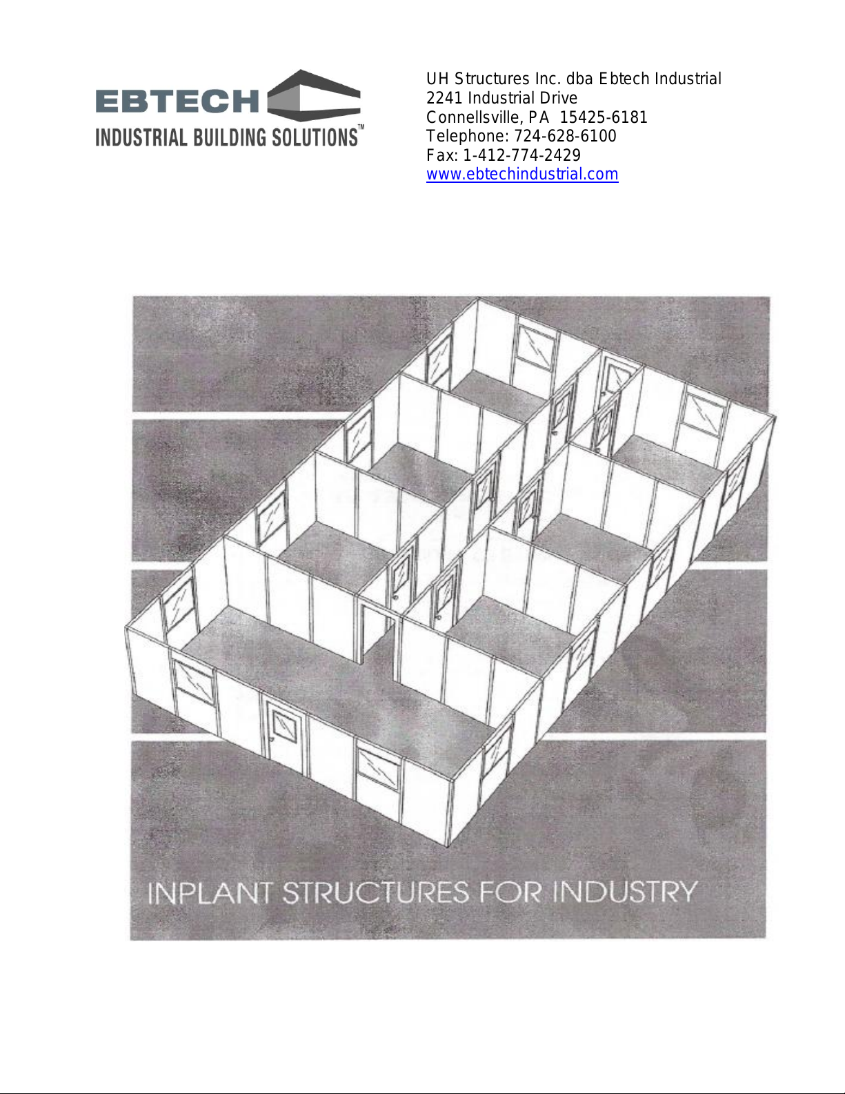
Office Installation Guidelines
Page 2

INTRODUCTION
These construction and installation guidelines are provided to assist in the
installation of the Ebtech products and may not apply to every situation.
Manufacturer accepts no responsibility or liability for the use of these or other
installation guidelines.
DESIGNER, INSTALLER, AND END USER SHALL DEFEND AND HOLD
EBTECH INDUSTRIAL HARMLESS FROM ANY AND ALL CLAIMS OR
DAMAGES CAUSED BY INSTALLER, IT’S AGENTS OR CONTRACTORS, BY
THEIR ACTIONS OR OMISSIONS, OR RELATED TO THE ASEEMBLY OF THE
EBTECH INDUSTRIAL MODULAR COMPONENTS.
ATTENTION: This installation guide is intended to provide general
information for the designer, installer and end user. The following guidelines
should help you safely and properly install the Ebtech modular structure.
We urge you, and anyone installing these products, to read these guidelines
in order to minimize risks of safety hazards and to help prevent voiding any
applicable warranties. This manual is a general installation guide and does
not cover every installation condition or requirement. You acknowledge that
it is solely your obligation for all safety requirements and code compliance.
Ebtech Safety Guideline Recommendations:
FOLLOW ALL OSHA REGULATIONS AND ANY OTHER SAFETY GUIDELINES
AND SAFETY BEST PRACTICES APPLICABLE TO YOUR LOCATION. -USE
APPROVED SAFETY EQUIPMENT, BELTS AND/OR HARNESSES OR OTHER
FALL PROTECTION EQUIPMENT AS REQUIRED.
Overview: This Ebtech modular structure is comprised of Ebtech wall panels and
support beams as well as other assembly components. The following installation
steps are presented as a general outline of the installation process. These are
manufacturer recommendations only. YOU ARE FULLY AND SOLELY
RESPONSIBLE AND SHALL HOLD EBTECH INDUSTRIAL HARMLESS FOR
ANY LIABILITY, CLAIMS, OR DAMAGES, FOR THE INSTALLATION AND
COMPLIANCE WITH ALL SAFETY REQUIRMENTS. Good construction and
safety practices should be followed at all times.
Page 2 of 20 Effective 09-14-2011 Rev004 Doc003
Page 3
TABLE OF CONTENTS
Section
Page #
Suggested Tool List
3
Parts Identification
4
Building Layout
5
Bottom Track Installation Recommendations
7
Wall Panel Installation Recommendations
8
Window & Window Panel Installation Recommendations
11
Top Track Installation Recommendations
12
Door Installation Recommendations
13
Steel Dust Cover Installation Recommendations
16
Acoustical Grid Ceiling Installation Recommendations
17
Roof Deck Support Beam installation Recommendations
18
Wall Starter Installation Recommendations
19
Stair & Landing Installation Recommendations
20
SUGGESTED TOOL LIST
1. Hammer Drill with 114" Percussion Bit
2. Cordless Drift with Bits
3. #2 & #3 Phillips Screw Tip with Magnetic Holder
4. Circular Saw with Carbide Tip Blade
5. Nut Drivers with 5116" and 114" Heads
6. Ratchet Wrench 5/8" Socket
7. Rubber Mallet
8. Metal Snips
9. Putty Knife with Wide Blade
10. Utility Knife
11. Hack Saw
12. Screw Drivers - Phillips and Flat
13. Measuring Tape and Ruler
14. Level – 48" Minimum Length
15. Large Carpenter's Square
16. Chalk Line
17. Gloves
18. Eye Protection
Page 3 of 20 Effective 09-14-2011 Rev004 Doc003
Page 4
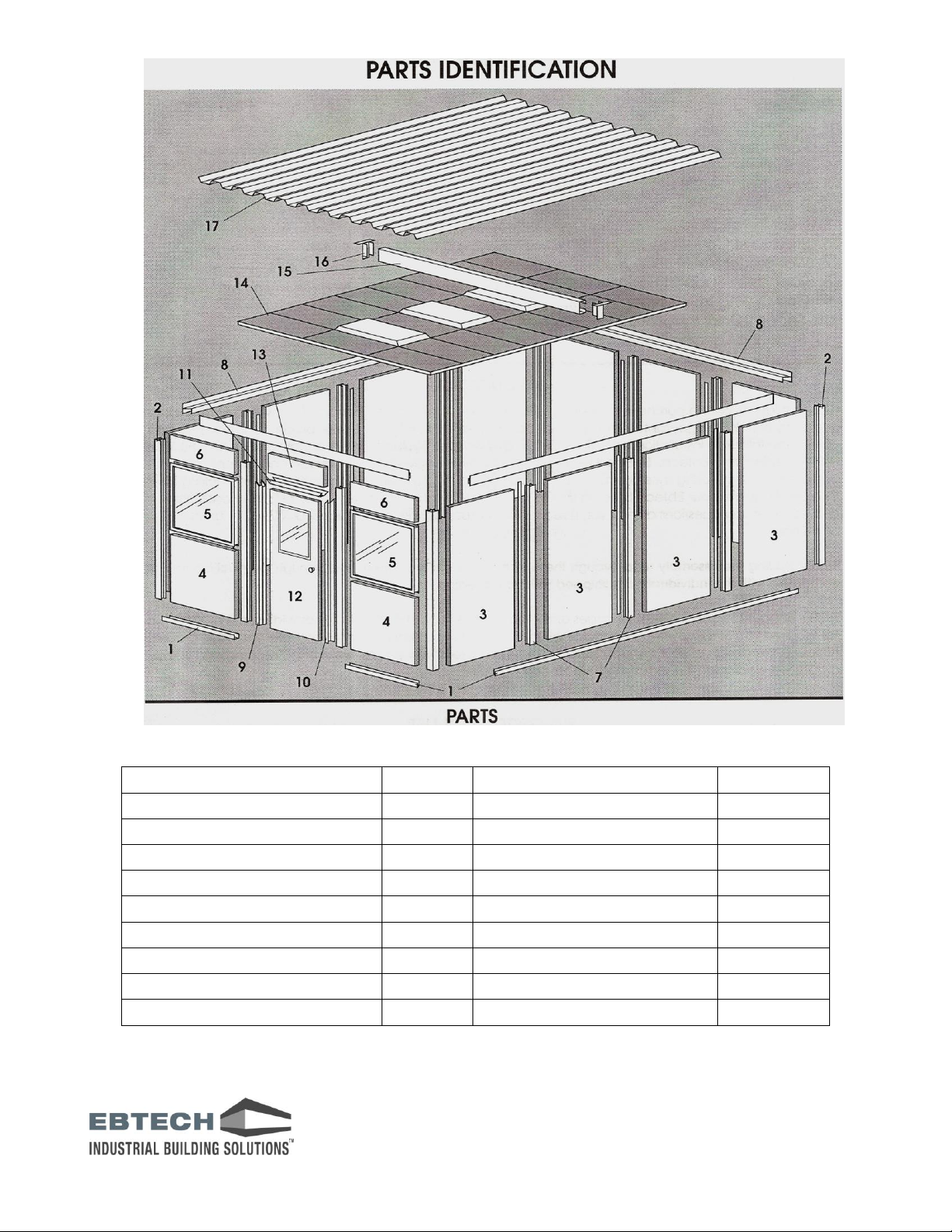
Part Description
ID #
Part Description
ID #
Bottom Track
1
Strike Side Door Jamb
10
Corner Post
2
Top Door Jamb
11
Wall Panel
3
Door (window optional)
12
Bottom Window Panel
4
Door Header Panel
13
Window
5
Acoustic Grid Ceiling
14
Top Window Panel
6
Support Beam
15
Wire Stud 1
7
Support Beam Hanger
16
Top Track
8
Steel Dust Cover
17
Hinge Side Door Jamb
9
Wire Stud Note #1:
EB-200 – 1 piece w/cover & EB-300 – 2 piece w/cover
Page 4 of 20 Effective 09-14-2011 Rev004 Doc003
Page 5
BUILDING LAYOUT
The proper and accurate installation of the Bottom Track is crucial to your building
assembly success. Therefore, we strongly recommend that you check and
recheck your measurements. A few extra moments taken now can save significant
time and frustration.
Step 1 – For ease of installation it is important that you work in a clean, safe, and
spacious area. For assembly purposes, allow several feet of extra space around
the building location. Sweep the work area all debris and remove any objects that
might impede the assembly process.
Step 2 – Refer to the Bottom Track Layout in Packing List for the exact
dimensions of your Ebtech building. Strike a chalk line on the floor for your first
wall. Where you begin chalking is not important chalking, but we suggest you
frequently verify your layout sheet for proper lengths and miters.
NOTE: All chalk lines will represent the outside edge of the Base Track.
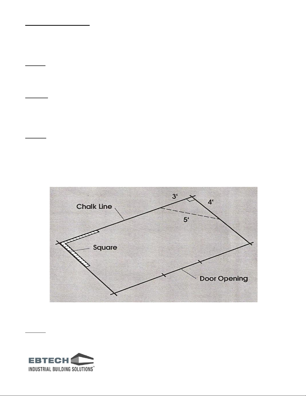
Step 3 – Construct a 90 degree corner at your walls using one of two methods
shown in Figure #1. Use a large square or the 3-4-5 triangular method to make an
accurate 90 degree corner. Strike a chalk line through this point to mark the
outside edge of the cross wall.
NOTE: It is very important this dimension be established accurately now because
it is very difficult to make modifications when you begin installation.
Figure #1
Step 4 – Complete the perimeter of your building using the dimensions shown on
the Bottom Track drawing.
Page 5 of 20 Effective 09-14-2011 Rev004 Doc003
Page 6
Step 5 – Locate any door openings and carefully mark these on the floor
accordingly. The space between the Bottom Track for each single standard size
door opening is 38 1/2”.
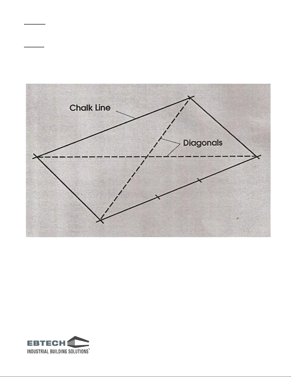
Step 6 – In a square or rectangular building an easy way to double check the
accuracy of your layout is to measure the diagonals. They should be the some
length. (See Figure #2 below)
Figure 2
Page 6 of 20 Effective 09-14-2011 Rev004 Doc003
Page 7

BOTTOM TRACK INSTALLATION RECOMMENDATIONS
Wood Floor
¼” x 1 ¼” lag bolts
Concrete Floor
Powder actuated fasteners, 1” nails with #3 charge or
1 ½” nails with #4 charge or various expansion
anchors
Steel Floor
#14x1” sheet metal screws
Step 1 –Ebtech provides you with carefully measured precut, mitered, and clearly
marked Bottom Track pieces. Refer to your Bottom Track drawing sheet included
in your packing list and begin placing the outside edge of your Bottom Track
pieces along the chalk lines you created in the building layout step.
Step 2 – Anchor the Bottom Track using appropriate for the type of floor in your
office/plant. Ebtech does not furnish these fasteners. A list of recommended
fasteners follows:
See figure #3 for fastener locations. Ensure measurements prior to installing
anchors, because removing anchors is difficult and may damage the Bottom
Track. Make sure you place a fastener near the end of each piece of track and
approximately every 3' along the length of the track.
Figure #3
Page 7 of 20 Effective 09-14-2011 Rev004 Doc003
Page 8

WALL PANEL INSTALLATION RECOMMENDATIONS
Step 1 – Beginning at a corner (choose any corner), place a Corner Post into the
Bottom Track (see figure #4).
Figure #4
Step 2 – Use the wall panel layout drawing provided packing list to determine the
walls panels to be inserted into the Bottom Track and Corner Post as shown in
Figure #5.
Figure #5
Page 8 of 20 Effective 09-14-2011 Rev004 Doc003
Page 9

Step 3 - Make sure the Corner Post is plumb and fasten it to the wall panels using
#8x5/8" self drilling screws. Place screws approximately 3" from the top of the wall
panels, through the Corner Post and into the wall panel as shown in figure #6.
Figure #6
Note:
Depending on building style and configuration, you will be installing H-Studs or
Wire Studs and Covers between wall panels. H-Studs are AL extrusions placed
between wall panels. EB-200 Wire Studs and Covers are made from two AL
extrusions and are shown in Figure #7. EB-300 Wire Studs and Covers are made
from three AL extrusions and are shown in Figure #8.
Figure #7 Figure #8
Page 9 of 20 Effective 09-14-2011 Rev004 Doc003
Page 10

Wire Studs and Covers are used to conceal electrical, data and communication
lines. It is recommended that you assemble the two EB-300 pieces together prior
to installing them inside the AL Bottom Track. Assemble loosely with #8x5/8" selfdrilling screws. Make sure a fastener is placed in each pre-punched hole of the
AL Wire Stud. You will be advised later in this manual when to tighten the screws.
We recommend you install any electrical or switch boxes inside the AL Wire Studs
prior to installing. The AL Cover Plates can be cut to fit around the electrical boxes
and snapped into place after all your wiring is complete.
Note: Make sure the AL Covers are facing the inside of the office.
Step 4 – Install the H-Stud or Wire Stud into the AL Bottom Track and over both
sides of the wall panel. Make sure the H-Stud or Wire Stud cover the previous
panel sides and is plumb. Care should be taken if you need to tap the stud into
place over the wall panel (a wooded block placed inside the stud will help prevent
many hammer marks).
Step 5 - Fasten the H-Stud or Wire Studs to both the AL Bottom Track and the
previous wall panel using #8x5/8" self drilling screws. Place screws approximately
3" from the top of the wall panels, through the H-Studs or Wire Studs and into the
wall panel as shown in figure #6.
Step 6 – Install successive wall panels and H-Studs or Wire Studs by repeating
steps the above steps.
IMPORTANT NOTE AND CAUTION:
TEMPORARILY BRACE WALLS AS NEEDED
MAINTAIN A SAFE AND SECURE AREA IN AND AROUND YOUR ASSEMBLY
ZONE
Page 10 of 20 Effective 09-14-2011 Rev004 Doc003
Page 11

WINDOW & WINDOW PANEL INSTALLATION RECOMMENDATIONS
Windows and Window Panels have three sections and are installed in a similar
manner as the regular Wall Panels. Consult the layout drawing for placement of
windows.
Step 1 – First install the bottom panel in the same manner as a regular Wall
Panel. This panel is usually 48" wide x 42" tall.
Step 2 – Next place the assembled window unit over the Bottom Wall Panel and
into Wire Stud.
Step 3 – Place the Top Panel over the window unit (See Figure #9). Make sure
the window unit is plumb and that all aluminum pieces are fit tightly against one
another. Windows should be flush with the surrounding walls.
Figure #9
Page 11 of 20 Effective 09-14-2011 Rev004 Doc003
Page 12

TOP TRACK INSTALLATION RECOMMENDATIONS
Once a wall section has been completed (see Figure #10), place proper mitered
and length AL Top Track over the H-Studs or AL Wire Studs and Wall Panels.
Consult the AL Top Track Layout Drawing as needed.
Figure 10
Fasten the Top Track to the Comer Posts and Wire Studs using the #8x5/8" self
drilling screws provided (Figure #11)
Figure 11
Continue to install wall panels and windows to complete the other office walls,
leaving the door panel as the last panel to install.
Page 12 of 20 Effective 09-14-2011 Rev004 Doc003
Page 13

DOOR INSTALLATION RECOMMENDATIONS
Step 1 – Install the two narrow door side panels in the AL H-Studs or AL Wire
Studs.
Step 2 – Install the two narrow AL H-Studs on top of the narrow door side panels,
these will cover the interface between the narrow side panels and the door header
panel.
Step 3 – Install the steel hinge side frame over the wall panel and outside of the
AL Bottom Track.
Step 4 – Install the steel door top jam mating the tabs in the side frame into the
top jam as shown in Figure #12.
Figure #12
Step 5 – Install the steel door strike side frame mating the tabs in the top jam as
shown in Figure #13. Tilting during the strike side frame assembly, will make this
a simple process.
Figure #13
Page 13 of 20 Effective 09-14-2011 Rev004 Doc003
Page 14

Step 6 – Ensure both steel hinge and strike side are plum, then insert #6x1 5/8"
self drilling screws to secure the steel door installation to the AL Bottom Track as
shown in Figure #14
Note: Make sure that you have the same Door Frame opening on the top and
bottom. Adjust the built-in plumb screws, if necessary.
Figure #14
Step 7 – Install the door header panel as shown in Figure #15.
Figure #15
Page 14 of 20 Effective 09-14-2011 Rev004 Doc003
Page 15

Step 8 – After removing the hinge pins. Install the three hinges sides on the door.
Step 9 – Install the three hinges sides on the steel door frame.
Step 10 – Hang the door and insert the hinge pins into the two halves of the
hinges as shown in Figure #16
Figure #16
Step 11 – Install the lockset.
Reminder Note: Go back and fully tighten all of the AL H-Studs or AL Wire Studs
screws in both the AL Bottom Track and the AL Top Track to ensure structure
integrity.
Page 15 of 20 Effective 09-14-2011 Rev004 Doc003
Page 16

STEEL DUST COVER INSTALLATION RECOMMENDATIONS
Note: For spans greater than 12 feet refer to Appendix A for placement and
installation recommendations of Support Beams prior to installing the Dust Cover.
Step 1 – Place corrugated roof panels on the AL Top Track one panel at a time.
Roof panels have lap joints on the sides.
Do not overlap roof panels beyond these joints until you reach the lost panel. The
last roof panel can be over lapped to fit. (See Figure 18) If building is square and
plumb, roof panels should butt securely to outside lip of AL Top Track.
Step 2 – Fasten roof panels to the AL Top Track approximately every 12" with
#10x¾” self drilling screws. Make sure you fasten the ends at each lap joint and at
least at one point in between. Fasten the sides every 24" at a minimum.
Note: Standard Roof Deck is non load bearing and intended to only support
lights and the ceiling. Be very careful when fastening lap joints.
Figure 18
Page 16 of 20 Effective 09-14-2011 Rev004 Doc003
Page 17

ACOUSTICAL GRID CEILING INSTALLATION RECOMMENDATIONS
See the Grid Ceiling Layout drawing included in the packing slip for the designed
pattern of the ceiling tile.
Step 1 – Install the Wall Angle around the entire perimeter between 6”–12” below
the Dust Cover. Fasten the Wall Angle to each AL H-Stud or AL Wire Stud with
#8x5/8" self drilling screws.
Note: It is best not to fasten the Wall Angles directly to the Wall panels.
Step 2 – Mark the locations of the Main Ceiling Tees with chalk line on the
underside of the corrugated roof panels. Insert the self drilling 5/8”x1 ¼”
acoustical eye screws along the chalk lines at 24” intervals at a minimum.
Step 3 – Thread the 12GA Tie Wires through the eye’s of the screws and loop the
Tie Wires into the Main Tee’s. See Figure #19.
Note: Make sure the Main Tees are level and at the same height from the floor as
are the Wall Angles.
Figure #19
Step 4 – Snap the Cross Tees into the Main Tees according to the Grid Ceiling
layout drawing.
Step 5 – Install the fluorescent light fixtures into the Grid Ceiling according to the
Grid Ceiling layout drawing.
Note: Recheck that the Main Tees are level, because of the weight of the light
fixtures, it may be necessary to adjust some of the Tie Wires.
Step 6 – Install the Ceiling Tiles into the grid according to the Grid Ceiling layout
drawing.
Page 17 of 20 Effective 09-14-2011 Rev004 Doc003
Page 18

ROOF DECK SUPPORT BEAM INSTALLATION RECOMMENDATIONS
Note: For spans greater than 12 feet Support Beams are needed to support the
corrugated steel roofing material.
The Support Beam should be located and installed according to the Wall Panel
layout drawing.
Step 1 – Place Steel Support Beam Hangers on the top of the AL Top Track and
directly over the AL Wire Stud. Fasten the Steel Support Hangers to the AL Top
Track with the screws provided.
Step 2 – Insert the Steel Support Beam into the Hangers. Secure the beam to the
hanger with two self drilling screws provided.
NOTE: The finished Steel Support Beam installation should resemble Figure #20
Figure #20
Page 18 of 20 Effective 09-14-2011 Rev004 Doc003
Page 19

WALL STARTER INSTALLATION RECOMMENDATIONS
A Wall Starter is necessary when attaching or starting a wall from an existing wall.
The Bottom Track should already be in place and butted up against the wall
before installing the Wall Starter.
Step 1 – Place the Wall Starter into the end of the Bottom Track then locate
against the existing wall. Ensure the Wall starter is plumb as shown in Figure #21.
Figure #21
Step 2 – Securely fasten the Wall Starter with an appropriate fastener for the type
of wall.
Page 19 of 20 Effective 09-14-2011 Rev004 Doc003
Page 20

STAIR & LANDING INSTALLATION RECOMMENDATIONS
(Figure #22)
Step 1 – Bolt columns to one piece landing platform.
Step 2 – Position landing per drawing and attach top stair clips.
Note: When raised into position the opening of the landing should face the
mezzanine.
Step 3 –Secure stair stringers to top clips.
Step 4 – Bolt stair threads to both stair stringers.
Step 5 – Anchor columns and bottom of the stair stringers in their final position.
Figure #22
Page 20 of 20 Effective 09-14-2011 Rev004 Doc003
 Loading...