

Page 1
EBS MICROBASS 3
EBS MICROBASS 3
USERS MANUAL
USERS MANUAL
www.ebssweden.comwww.ebssweden.com
Page 2
EBS MICROBASS 3EBS MICROBASS 3
USERS MANUALUSERS MANUAL
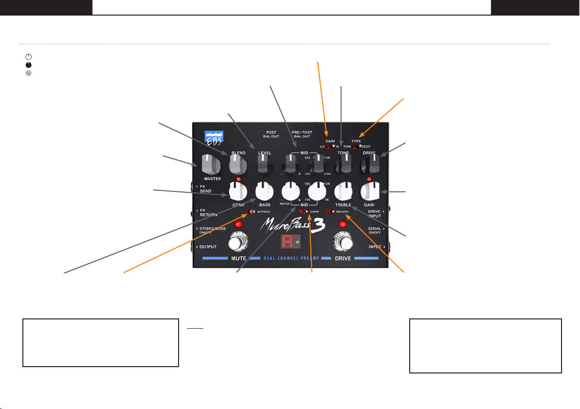
CHANNEL CONTROLS, SWITCHES & OUTPUTS
CLEAN CHA NNEL = WHITE KNOB S
DRIVE CHA NNEL = BLACK KNO BS
BOTH CH ANNELS = GR AY KNO BS
BLEND sets the mix level between the clean
channel and drive channel when the drive
channel is active. To jump between the Clean
and Drive channels, set this knob to the max
position and set the Serial switch to Off.
MASTER controls the volume on the Output jack.
The balanced outputs ( XLR) are not af fected by
the set ting of this knob.
COMP. This control knob sets the
compression ratio, i.e. The signal strength
relation between the input and output; the
higher the ratio the more compression. The
LED indicates when the compressor responds
during play. It is a low noise compressor/
limiter that will tightening up the sound and
prevent the preamp from saturating at peaks
when approaching the headroom limit.
BASS is a 'shelving' type
12dB/oct slope phase
compensated bass filter
with a wide gain range.
MUTE FOOT SWITCH. Mutes the balanced
outputs and the master output.
Fx Send is not affected by this function.
The Mute switch also enables the built-in tuner
for silent tuning.*
* An internal switch can set the tuner to be active a t all times.
BYPASS. This switch
bypasses ALL filters in the
clean channel and sets a
flat frequency response.
MID is a peaking filter for the drive
channel. The two knobs wor ks in
conjunction. Pick your frequency with
the right control, and boost or cut with
the lef t control in the chosen range.
LEVEL sets the output volume for
the Drive channel.
MID. These two knobs works
in conjunc tion. Use the right
control to pick a frequency.
Use the left control to boost
or cut the gain in the range
of the chosen frequency.
Note: When the left control
is set to Notch, you can use
the right control to find and
erase a precise frequency that
causes unwanted feedback
(a common issue with upright
basses in larger rooms).
REFERENCE GUIDE
GAIN select s between a low- and high-gain drive engine.
TONE shapes the tone range of the drive engine.
Flat set ting when turned all the way up.
TYPE sets the drive tone character to THIN or
DEEP (neutral in the between position). The
deep position compensates for low-frequency
loss at very high gain.
DRIVE controls the amount of gain in the tube
emulation stages (engines), and provides an
extra gain all the way up to 40 dB. This control
also compresses the sound when tur ning up level
up to maximum, producing pure limitation.
GAIN adjusts the input signal level for the EBS
MicroBass 3. An optimum level is when the peak
led starts flashing when playing hard on your
instrument. A cor rectly set gain is vital for the
signal processing to work properly.
TREBLE is a shelving type filter controlling the
higher mids and treble registers, giving presence
and ambiance to the sound.
CHARACTER FILTER
When ac tive, bass and
treble are boosted while the
midrange gain will be slightly
dropped, known as a smiley
EQ curve. This way the sound
will be preshaped before the
final adjustments using the
other features of the preamp.
BRIGHT is an advanced high pass filter that
produces a bright high-treble timbre, without
adding any noise. This switch gives a gain of
10 dB at 10kHz.
DRIVE FOOT SWITCH - Engages the drive
channel. The clean channel is always ac tive,
but if the BLEND control is turned all the way
up, in parallel mode, this switch will make the
sound jump from the clean channel to the dr ive
channel when activated.
CONTINUED ON TH E NEX T PAGE SPREA D >>
www.ebssweden.comwww.ebssweden.com
Page 3

FX SEN D & RETURN. EBS MicroBass3 is provided with an effec ts loop for
A/B
use with external units such as box or rack effects. The loop puts the external
effects af ter both channels EQs and the channel selector (Drive footswitch).
STEREO MODE ON/OFF. By pushing this switch the return jack goes into
C
TRS operation for stereo mode. When active, the Balanced Outputs will turn
into Lef t and Right outputs rather than post/pre. The stereo effect will also be
heard through the headphones output. For the stereo effec t, use an external
effect with s tereo output last in line, and connec t to the FX return using a
Y-split cable, such as the EBS ICY-30.
D
OUTPUT. This is the master output jack to be connected to another amp or
power amplifier.
A
B
C
D
DRIVE INPUT. This input is a direct input to the Drive channel in parallel
E
mode and can be used to mix two sources, e.g. between two pickups on an
instrument where applicable. Note: In conjunction with the Blend knob at
max, and by choosing the LO gain engine (and modest or minimum Drive
setting) it can serve as an input for a second instrument. Then you will
use the drive channel to tweak the EQ individually for that instrument (not
necessarily using any overdrive).
SERIAL ON/OFF. This switch controls from where the Drive channel should
F
take its’ signal. In default mode, parallel, the source is taken from the main
input or the Drive Input when used. In serial mode, the source is taken from
the output of the Clean channel, so the channels are connected in serial.
INPUT - The main input is a low noise, high impedance instrument input.
C
EBS MICROBASS 3EBS MICROBASS 3
K
J
I
H
L
M
N
AUX IN. Auxiliary input to be
Note: The balanced outputs offers
high-quality ’ line box’ signals for
connecting to PA mixing consoles or
to studio or broadcast recording units,
with high noise immunity. The output
level controlled by the MASTER knob
does not af fect these outputs.
------------
H
E
F
G
POST BAL OUT. Post EQ signal that is
taken immediately before the Master
knob (serve as the Left channel output
when using FX Return in ’stereo mode’).
PRE/POST BAL OUT. This output send
I
various signals depending on which
mode is selected:
1) When the switch is in its’ outer
J
position the signal is taken before (PRE)
any of the pedals the EQ.
2) When the switch is engaged this
J
output normally serves as post Clean
channel EQ only-output. However, if
the ’stereo mode’ for the FX return is
activated at the same time, it will ser ve
as the Right channel output, post EQ.
GND LI FT. Eliminates ground noise
K
and hum. When required, press the
Gnd Lif t switch to disconnect the
ground from the balanced outputs.
L
monitored only with headphones.
This input has no level control and
the volume should be adjusted by
the source.
M
PHONES. Connect your
headphones here for silent
practicing. The volume from the
MB3 is controlled by the MASTER
knob where the Aux In needs to be
adjusted from the signal source.
N
DC INPUT. Connec t the power
supply here, only 9V DC, 1000 mA
(supplied in package).
USERS MANUALUSERS MANUAL
www.ebssweden.comwww.ebssweden.com
Page 4

TECHNICAL SPECIFICATIONS - MICRO BASS 3
EBS MICROBASS 3EBS MICROBASS 3
USERS MANUALUSERS MANUAL
Clean Channel:
Input Impedance: Parallel mode 1.5 Mohms // 44 pF
Serial mode 10 Mohms // 22 pF
Gain: Gain Range min/max -oo/+30 dB
Gain Peak LED +10 d B v
Frequency Response +0/-3 dB 20-20.000 Hz
Character: Filter Type Shelving High/Low Pass
Gain: Lo +6 dB @ 80 Hz
Mid -2 dB @ 90 0 Hz
Hi +3 dB @ 7.5 kHz
Bright: Filter Type Shelving.
Gain: +10 dB @ 10 kHz
Filter Section:
Bass Filter: Typ e 12 dB/oct. Shelving.
Gain Range +/- 18 dB @ 60 Hz
Mid Filter: Typ e Bandpass Filter.
Freq Range 50 - 5.00 0 Hz.
Q - Boost 0.5 - 1.3.
Q - Cut 0.5 - >5.
Gain Range +/- 12-15 dB
Treble Filter: Typ e Shelving.
Gain Range +/- 18 dB @ 8 kHz
COMP/LIMIT: Comp Gain 0 dB
Attenuation max 24 dB
Compression Ratio max 3:1
Attack (80%) typ <10 ms
Release (80%) typ 100 ms
FOR MORE PEDALS, A MP S &
ACCESSORI ES, SCAN THE QR-CO DE TO VI SIT
WWW.EBSSWEDEN.COM
Drive Channel:
Input Impedance: 1.8 Mohms // 22 pF
Drive: Gain Range 40 dB
Drive Engines:
Lo: Typ e 2nd harmonics sof t
Hi: Type Symmetrical 2-stage with
+18 dB gain
Type Switch: Thin/Normal/Deep Pre Drive EQ
Filter Section:
Tone Filter: Typ e 6 dB/oct. Low Pass.
Frequency Range 700 - 20k Hz
Mid Filter: Ty pe Bandpass Filter.
Frequency Range 100 - 4.500 Hz.
Q 1.2
Gain Range +/- 15 dB
Common Features:
Effects Loop: Loop Signal Level nominal -10 dBv
Gain Unity (1:1)
Output Impedance <10 0 o h m s
Input Impedance >200 kohms // 22 pF
Phones Out: Recommended Imp. 32 - 200 ohms
Aux Input: Input Impedance 20 kohms
Nominal Level -10 d Bv
Output: Output Impedance <1 kohms
Signal Level nominal 0 dBv
Balanced Outputs: Output Level nominal -20dBv
XLR Connections 1-GND, 2-Hot, 3-Cold
Options Pre/Post EQ, L/R Ch.
in stereo mode
Auxiliary Info:
Power Requirements Idle 450m A @ 9V.
Max 750mA @9V
(with headphones at
max output level)
Dimensions (WxDxH): max 168 x 124 x 53 mm /
6.6” x 4.9” x 2.1”
Weight: 660 g ( 1.5 lbs.)
Specifications are subjec t to change without notice.
www.ebssweden.comwww.ebssweden.com
Page 5

USERS MANUAL
EBS MICROBASS 3
BLOCK LAYOUT SCHEME - MICRO BASS 3
www.ebssweden.com
 Loading...