

Page 1
M7000
BM7000
Installation manual
(piezo version only)
M7000 acoustic & flash sounder
PIEZOELECTRIC, OUTDOOR, WITHOUT BACK-UP
FOR 12 V INTRUSION SYSTEMS
BM7000 acoustic & flash sounder
PIEZOELECTRIC, OUTDOOR, WITH BACK-UP
FOR 12 V INTRUSION SYSTEMS
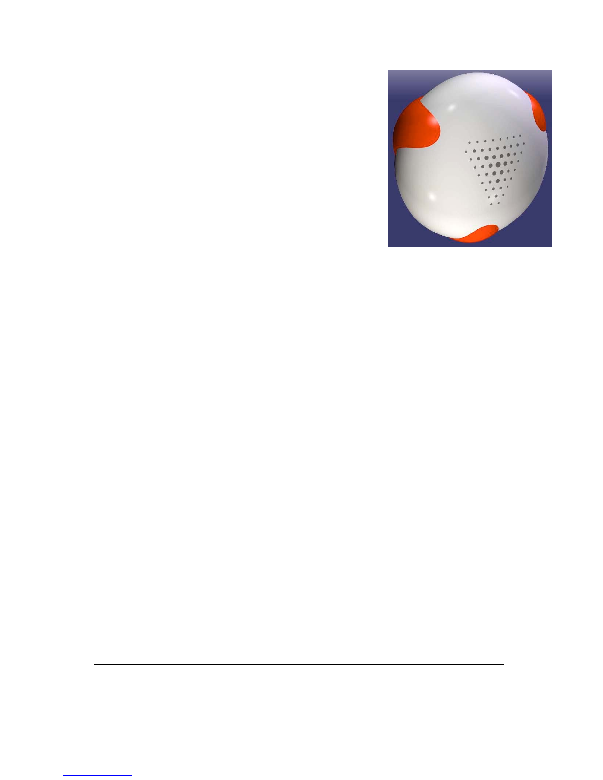
We are very thankful that you have chosen our new sounder.
Its beautiful and unique shape will distinguish your installations. And it helps you to
install the sounder straight…
There are two models: piezoelectric and dynamic. This manual refers to the piezoelectric one.
The sounder needs 0,5 Amps approximately when in action. Please check if the intrusion panel can give it.
It is recommended to install the sounder:
¾ Close to the panel to avoid significant voltage drops on wires,
¾ High enough to make the sounder difficult to reach.
Installation
Before you take the ladder…
1. Unscrew the central mounting screw and remove the cover.
2. Selection of acoustic tone
You can select one of three tones using a jumper marked S1/S2/S3. Default is S1. This is the loudest tone as well. No
jumper is the same as S1.
To listen to the tones:
¾ Connect power (0V = GND, +13,8V),
¾ Give 0V (GND) to the S input for several seconds,
¾ Repeat with all S1/S2/S3 positions.
This is a test method only! Do not use it during a normal operation!
3. Selection of controls
Think it over carefully! To select the control you have to cut a jumper(s).
This is a reliable method resistant to all weather conditions but the undo function is difficult…
To switch the tone (or lamp) on you can give positive signal (nominal value is +12V) or negative one (0V = GND) or
remove such signals.
You have two control inputs for siren and lamp separately. You can use different signals or the same ones. You
can short circuit the inputs or leave them separately.
To select the control signal for the siren… Cut the jumper(s)
Active state: + 12V - control signal + 12V gives the tone
Non active states: 0V (GND) or high impedance (break)
JS1 and S
Active states: lack of + 12V (break or 0V)
Non active state: + 12V *- control signal + 12V blocks
JS1
Active state: 0V (GND) - control signal 0V gives the tone
Non active states: + 12V * or high impedance (break)
JS2
Active states: lack of 0V (break or + 12V)
Non active state: 0V (GND) - control signal 0V blocks
JS2 and S
* It is a good idea to use positive signal as non-active one. You can easily monitor the line in such mode. The 4,7 k
Ω
resistor is installed as EOL in the sounder. If your control panel needs smaller EOL you can add a resistor between S and
GND inputs. The formula to calculate it is as follows:
Page 2

4,7 x EOL
R = ----------------------
4,7 - EOL
R is the value of additional resistor (in k
Ω
) to add.
EOL is the value your panel expects (in k
Ω
).
To select the control signal for the lamp… cut the jumper(s)
All options as above for the siren. Notes referring
to line monitoring are the same.
as above, but jumpers are
marked L, JL1 and JL2
On the ladder...
The sounder is equipped with one lamp, which should look down.
4. Position the sounder on the wall. The cables should go thru the hole on the left side of the sounder. Mark the place of the upper
mounting screw.
5. Drill the hole 12 mm dia. for upper mounting screw. Insert the plastic plug (delivered with the sounder). Mount the sounder.
6. Position the sounder. Mark 3 remaining holes.
7. Drill the holes, insert the plugs, mount the sounder firmly.
8. Connections
In the table below you can see the description of the connector of the sounder.
S L GND +13,8 SAB (2 terminals) R (2 terminals)
siren control
signal
lamp control
signal
ground
(supply
negative)
supply
positive
sabotage line (tamper),
polarity not important
EOL of sabotage
line
Connect:
¾ first EOL of sabotage line
¾ then sabotage line,
¾ controls,
¾ Power supply.
9. Fit the cover.
Main technical parameters
Power supply (nominal 13,8V) 9 – 15V
Current consumption (at 13,8V)
Quiescent
Alarm (acoustic only)
Alarm (optical only)
Alarm (acoustic and optical)
10 mA
200 mA
400 mA
600 mA
Control input current +/-3 mA
Connectors with screws
Weather protection of the pcb special resin
Acoustic signal
piezoelectric driver
Tone choosing jumper, 1 of 3
Tone 1 117 dB, at 1 m
Tone 2 116,5 dB, at 1 m
Tone 3 116 dB, at 1 m
Optical signal
4 Philips mini bulbs, 12V, 5W
Time of the flash 0,25 s
Frequency of the flashes 1 Hz
Colour red
Protections
Tamper line with EOL according to panel
specification
Detection of foam
Detection of opening the housing
Detection of pulling the sounder from the wall
Housing
Polycarbonate
Diameter
24 cm
Environmental conditions
Operating temperature
-25
÷
+ 70 deg. C
Storage temperature
-25
÷
+ 70 deg. C
Humidity 100%
 Loading...