

Page 1

GPRS TRANSMITTER
LX1NB-5L
Installation and
Programming short manual
Version of the manual: v1.6
Date of issue: 2015.04.03
Page 2
LX1NB-5L Short manual Page 2 / 24
DECLARATION OF COMPLIANCE
We, EBS Sp. z.o.o. declare with full responsibility that the present
product meets all requirements provided for in the Directive
1999/5/EC of European Parliament and Council dated 9 March 1999
The copy of the “Declaration of Compliance” can be found at
http://www.ebs.pl/en/certificates/ .
IMPORTANT INFORMATION
Crossed symbol of a trash bin means that at the territory of European
Union, the product, after finishing its useful life, shall be disposed of
in a separate, especially dedicated collection point. It refers to the
equipment itself and its accessories marked with that symbol. The
products shall not be disposed of together with non-sortable
municipal waste.
The content of the document is presented “as is”. The present document shall not be
deemed to be providing any warranties, either express or implicit, including but not
limited to, any implied warranties of merchantability or fitness for a particular
purpose, unless it is required by relevant law. The manufacturer reserves the right to
amend the present document or withdraw it any time, without notice.
The manufacturer of the equipment promotes the sustainable development policy. It
reserves the right to modify and improve any functions of the product described in
the present document without previous notice.
The availability of particular functionalities will depend on the software version of the
equipment. Details can be found at the nearest dealer of the equipment.
In no event, the Manufacturer shall be held liable for any loss of data or loss of
profits or any specific, incidental, consequential or indirect damages caused in any
way.
MANUFACTURER
EBS Sp. z.o. o.
59 Bronislawa Czecha St.
04-555 Warsaw, POLAND
E-mail: sales@ebs.pl
Technical support: support@ebs.pl
Webpage: www.ebs.pl
Page 3

LX1NB-5L Short manual Page 3 / 24
CONTENTS
CONTENTS .......................................................................................................... 3
1. GENERAL INFORMATION .......................................................................... 4
1.1. CAPABILITIES .......................................................................... 4
1.2. FUNCTIONALITY ...................................................................... 4
1.2.1. Relay output ...................................................................... 4
1.2.2. Clip and callback ................................................................. 4
1.2.3. Administrators .................................................................... 4
1.2.4. Users ............................................................................... 4
1.3. SPECIFICATIONS ...................................................................... 5
1.3.1. Functional ......................................................................... 5
1.3.2. Technical .......................................................................... 5
1.3.3. Layout ............................................................................. 6
1.3.4. Terminal description ............................................................. 7
1.3.5. Installation and wiring .......................................................... 7
1.3.6. Input configuration .............................................................. 8
1.3.7. Relay configuration .............................................................. 8
2. INSTALLATION ........................................................................................... 9
2.1. FIRST RUN ............................................................................. 9
2.2. RESTORING DEFAULT PARAMETERS .............................................. 9
3. CONFIGURATION ..................................................................................... 10
3.1. CONFIGURATION TOOL ............................................................ 10
3.1.1. First run ......................................................................... 10
3.1.2. Relay configuration ............................................................ 11
3.2. SMS COMMANDS .................................................................... 12
3.2.1. First run ......................................................................... 12
3.2.2. Commands ...................................................................... 12
4. LED INDICATORS ..................................................................................... 19
4.1. LOGGING TO GSM NETWORK ..................................................... 19
4.2. GSM RANGE .......................................................................... 19
4.3. DATA TRANSMISSION .............................................................. 20
4.4. PROGRAMMING...................................................................... 20
4.5. SIM CARD ERROR ................................................................... 20
4.6. FACTORY DEFAULT RESTORE .................................................... 21
4.7. SYSTEM ERROR ..................................................................... 21
5. REVISION HISTORY ................................................................................ 21
Page 4

LX1NB-5L Short manual Page 4 / 24
1. GENERAL INFORMATION
LX1NB-5L is a SMS/GPRS switch in an IP65 plastic enclosure for the control of gates, doors,
lighting, pumps, Generators, HVAC etc with CLIP or SMS.
1.1. CAPABILITIES
LX1NB-5L offers the control of a relay with NC and NO outputs. Up to 5 Administrators
and 500 Users can be configured.
The Transmitter offers:
clip functionality
callback option
“allow all” option
periodic status information messages
account balance check
1.2. FUNCTIONALITY
1.2.1. Relay output
The relay output can be activated either by a user’s call or by an admin’s SMS
command. It can be configured to activate for a set amount of timed or toggle mode.
Toggle mode means that the output state will change every time a user call is
detected.
1.2.2. Clip and callback
The device will reject every call after 3 or 4 rings. If the calling number is authorized,
the relay will be activated. If a callback option is activated, LX will return a call to the
user.
1.2.3. Administrators
Administrators can configure the device using SMS commands explained below.
They cannot activate the relay by CLIP unless they are programmed as a user, they
can activate the relay by sending an SMS command. Up to 5 administrators can be
programmed.
1.2.4. Users
Users can call the device in order to activate the relay. Up to 500 users can be
programmed. A call from a non-users number will not activate the relay.
NOTE: It is possible to program the same phone number for both
administrators and users. In that case this number will be authorized to
perform actions available for both groups.
Page 5

LX1NB-5L Short manual Page 5 / 24
1.3. SPECIFICATIONS
1.3.1. Functional
Inputs:
(programmable)
4 signal inputs (NO, NC, EOL-NO, EOL-NC, DEOL-NO,
DEOL-NC)
Outputs:
(programmable)
2 (1 x open collector & 1 x relay)
Operation modes:
GPRS transmission only
SMS transmission only
GPRS and SMS transmission
Messages:
Sending of text messages for defined mobile phones
Configuration:
Remote – via GPRS link
Remote- SMS
Remote – CSD will be phased out
Locally –from PC with the use of software and GD-PROG
cable with RS-232 link
Security:
SMS/GPRS transmission – AES encoding
Loading of OUT1
output
50 mA
1.3.2. Technical
Voltage
13.8 V DC
(12 – 14 V DC)
Current/Power consumption
(average/max)
60 mA /340 mA
@13.8 V DC
Dimensions
125x115x60mm
Weight
280g
Working temperature
-10°C to 55°C
Working humidity
5% to 93%
IP rating
IP65 (Dust tight, water jets)
Page 6
LX1NB-5L Short manual Page 6 / 24
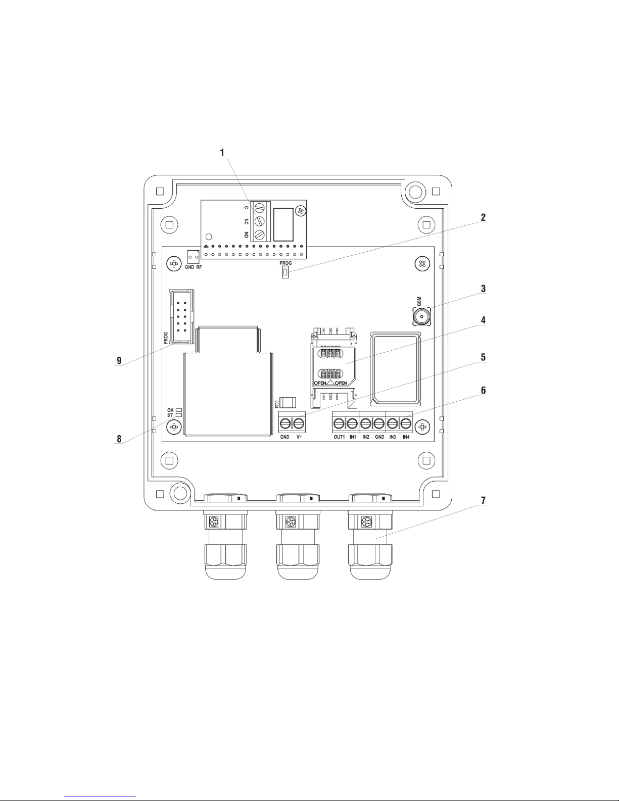
1.3.3. Layout
Below is a schematic of the LX1NB-5L with the explanations of its components.
1. Relay outputs: C (Common), NC (Normally Closed), NO (Normally Open).
2. PROG button.
3. GSM antenna socket.
4. SIM card slot.
5. Output and input terminals
6. Power supply terminals (12V DC).
7. Antenna, Relay and Power Supply glands.
8. Status LEDs.
9. PROG socket (configuration).
Page 7

LX1NB-5L Short manual Page 7 / 24
1.3.4. Terminal description
Terminal
Connection description
C, NC, NO
Relay outputs. Connection to external device that is to be
controlled by switches relay.
GND
Device ground, common for other input and output
IN1 - IN4
Signal inputs. Possible connection of detectors
contacts or alarm control panel outputs. GND terminal
is common for all inputs.
OUT1
Type OC output. It may control external device.
Provides ground during activation.
V+
Connect to the positive pole (+13,8V) of the power
supply.
GND
Connect to the negative pole of the power supply.
MANUFACTURER RESERVES THE RIGHT TO AMEND APPEARANCE OF PRINTED CIRCUIT
WITH NO EFFECT ON FUNCTIONALITY OF DEVICE.
1.3.5. Installation and wiring
All connections must be made with the power off.
Connections of wires shall be made with due care to prevent any faults or dead
shorts.
Wires should enter the enclosure using the installed cable glands.
The device is equipped with a built-in GSM antenna. In areas with poor GSM
signal it is possible to use an external GSM antenna. (Not included in the kit). In
order to wire the external antenna connector into the housing, remove one of the
cable glands and insert the supplied rubber grommet.
After checking all the connections, you can connect an external power supply.
Page 8
LX1NB-5L Short manual Page 8 / 24
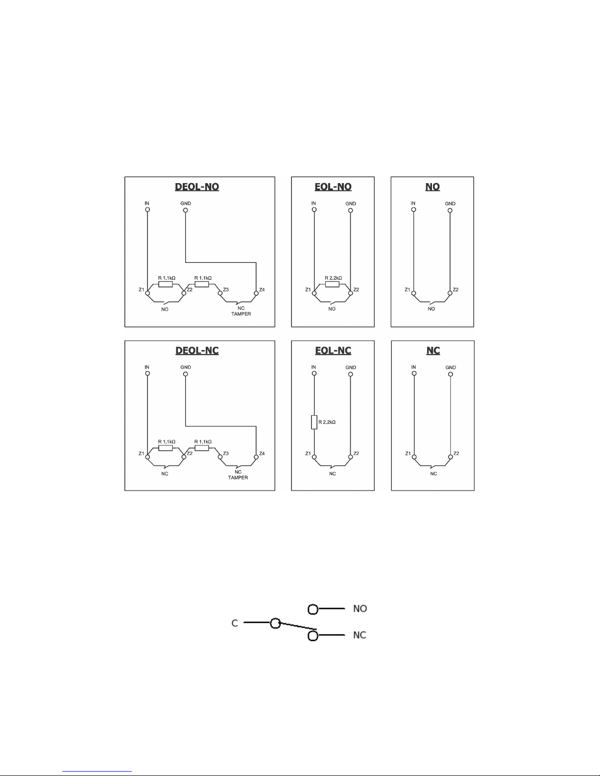
1.3.6. Input configuration
Inputs IN1 - IN4 can work as normally closed (NC) or normally open (NO).
Additionally inputs might be configured as end of line (EOL-NO or EOL-NC) with
resistors 2,2kΩ or as double end of line (DEOL-NO or DEOL-NC) with resistor
1,1kΩ.
Figure 2. Configuration of input lines
1.3.7. Relay configuration
Three terminals are available: Normally Closed (NC), Normally Open (NO) and
Common (C). Please refer to schematic below:
Figure 3. Schematic of Relay outputs
Page 9

LX1NB-5L Short manual Page 9 / 24
2. INSTALLATION
CAUTION!
For the device to work properly, voice mail has to be disabled
2.1. FIRST RUN
CAUTION!
SIM Card has to be removed from the device before first run
Please switch the power supply off before following any of the below instructions.
Device can be configured either by using SMS commands or by provided Configuration
Tool:
If you intend to use Configuration Tool, please connect the programming cable
and select the programming mode. Switch the power supply on. Please refer to
chapter 3.1 for further instructions.
If you intend to configure the device by SMS Commands, please either set SIM
Card’s PIN to “1111” or disable it. You can insert the SIM card into the SIM Card’s
slot now. Switch the power supply on. Please refer to chapter 3.2 for further
instructions.
2.2. RESTORING DEFAULT PARAMETERS
You can restore default configuration by following these steps:
1. Turn off the power supply
2. Press and hold the PROG button
3. Turn on power supply – ST and OK LEDS should turn on
4. Wait for ST and OK LEDS to start flashing
5. Release PROG switch.
Default configuration has now been restored.
Restoring factory defaults configures the device as follows:
Administrators are cleared
Call back option is turned off
“Allow any” option is turned off
Periodic status info is turned off
Account balance check code cleared
Admin password reset to “0000”
User’s memory is NOT affected by this operation, to clear user’s memory,
please refer to the DELETEALLUSERS command.
Page 10

LX1NB-5L Short manual Page 10 / 24
3. CONFIGURATION
3.1. CONFIGURATION TOOL
CAUTION!
GPRS transmitter’s configurator and full operation manual, describing how to
use this software may be downloaded at www.ebs.pl
(login: ebs, password: ebs)
To use the configuration tool, please connect the programming cable GD-PROG or
configuration device SP-PROG into the PROG socket. Select the programming mode and
wait for the device to enter the service mode (OK LED on, ST LED blinking). Start the
configuration tool.
To read the current configuration, please select
Operations->Read.
Choose the
connection you wish to use, enter the Service Code (default: 1111) and press
Read
.
To save the new configuration, please select
Operations->Write.
Choose the
connection you wish to use and enter the Service Code (default: 1111). In
addition, you can set the date and time. Press
Write.
3.1.1. First run
Select
File->Connections
and on the
RS232
tab please configure a new connection:
put in a name, select the correct COM port and press the
Add
button. The new
connection should appear on the list below the
Add
button. Press
Close
in the lowerright corner of the window. Read the current configuration (explained above). Please
select the 1.Access option and please put in the correct PIN for your SIM card. Save
the new configuration (explained above). You can now insert the SIM Card into the
SIM Card Slot.
Page 11

LX1NB-5L Short manual Page 11 / 24
3.1.2. Relay configuration
Please select the 3. Inputs/Outpus option. Select the
Relay
(OUT 2) tab.
Explanation of the fields:
Admins - this section allows you configure the administrators
programmed in the device. At least one administrator is required for
the device to work properly.
Authorization
o Password – this field allows you to set the administrators
password used to authorize text messages sent to the device.
o Account balance check code – this code will be used when a
GETBALANCE command is sent. This code is dependant on the
SIM card operator.
o Allow any number – this option will make the device authorize
any number calling in, activating the relay. Checking this option
will disable the users field.
Users – this section allows you to manage the user’s data base. You
can search the list, add/delete numbers and save or read the list from
a CSV file with the fields separated by semicolons.
Options
o Callback Enable – checking this option will make the device call
back the user in order to confirm relay activation request.
o Output activation time – this option allow you to set the time for
which the relay will be activated after receiving a call from the
authorized number or the OUTPUT=ON text command. Selecting
the Bi-stable checkbox, will set the output in to toggle mode,
which will activate / deactivate the relay with every authorized
call. OUTPUT=ON command will have a permanent effect in the
toggle mode.
o Periodic information – this checkbox will enable periodic
information feature. You can set day period and exact hour at
which periodic information will be sent. Periodic information
contains the number of programmed users, the number of
programmed administrators and the GSM signal strength. Text
messages with this information will be sent to every configured
administrator.
Page 12

LX1NB-5L Short manual Page 12 / 24
3.2. SMS COMMANDS
3.2.1. First run
First step is to add a new administrator. At least one administrator is required – if you
don’t setup any administrators you will not be able to change the password. To add
the administrators please refer to ADMINADD command. When administrator is set,
you can setup your new password – please refer to PASSWORD command.
NOTE: please be cautious when adding first administrator to the device’s memory. If
you send a wrong admin number, you might loose access to the advice. Only
restoring factory defaults will enable you to setup administrators again.
3.2.2. Commands
Every command has a strict format: <Current password>_COMMAND for
commands that do not need any parameters, and: <Current
password>_COMMAND=<Param1>,<Param2> for commands that require
parameters. *Symbol “_” is a space*. System will respond to most of the
commands.
Some of the commands can be sent in one text message, one after another. To send
a multi-command message, please use following format: <Current
password>_COMMAND=<Param1>,<Param2>_COMMAND=<Param1,Par
am2>...etc.
Only administrators can issue SMS commands. Below is a list of all available
commands, along with the response they will return and the information whether
they can be sent in a multi-command text message.
TABLE CONTENT EXPLANATION
Command title
Command
Command format
Response
Command response
Single/Multiple
Information whether this command can
be send in a multi-command text
message.
Command comments/examples
Page 13

LX1NB-5L Short manual Page 13 / 24
COMMANDS LIST
Change password
Command
PASSWORD=<new password>
Response
‘Password changed’
or error message
Single/Multiple
SINGLE
This command can be used to change current password. Default password is 0000.
Before the password can be changed, at least one admin has to be programmed.
<new password> should be a sequence of digits, length of password should not
exceed 31 digits.
Example: 0000 PASSWORD=1234 will change current ‘0000’ password to ‘1234’.
Add new admin
Command
ADMINADD=<index>,<phone number>
Response
No response
Single/Multiple
MULTI
This command can be used to program administrators’ phone number under a given
index.
<index> should be a digit from 0 to 4.
<phone number> should be a phone number with the country code, but
without ‘00’ or ‘+’ prefix. Phone number length should not exceed 31 digits.
Example: 1234 ADMINADD=0,44888777666 will save ‘44888777666’ number under
admin ‘0’ or the first admin.
Get current administrators list
Command
GETALLADMINS
Response
List of all administrators in following format:
<index>:<phone number>
Single/Multiple
SINGLE
This command can be used to get a list of all administrators.
Example: 1234 GETALLADMINS will return a list of all administrators and will look
similar to this:
0:44888777666
1:
2:44900800700
3:
4:
Page 14

LX1NB-5L Short manual Page 14 / 24
Delete admin
Command
ADMINDELETE=<index>
Response
No response
Single/Multiple
MULTI
This command can be used to delete admin numbers under a given index.
<index> should be a digit from 0 to 4.
Example: 1234 ADMINDELETE=2 will delete administrator number saved under index
2.
Allow any number
Command
ALLOWALL=<ON/OFF>
Response
AllowAll configuration changed
or error message
Single/Multiple
SINGLE
This command can be used to allow any number to activate the relay by a call.
<ON/OFF> should be either ON or OFF word, depending on what configuration one
wishes to upload.
Please note, that this command does not delete any users’ numbers nor does it
disable the admin authorization.
Example: 1234 ALLOWALL=ON will authorize relay activation by a call from any
phone number
Add user
Command
USERADD=<phone number>
Response
No response
Single/Multiple
MULTI
This command can be used to add a new user’s phone number.
<phone number> should be a phone number with the country code, but
without ‘00’ or ‘+’ prefix. Phone number length should not exceed 31 digits.
Example: 1234 USERADD=07891234567 will add given phone number to the
authorized users list. Must be 11 digit numbers.
Page 15

LX1NB-5L Short manual Page 15 / 24
Verify user
Command
USERCHECK=<phone number>
Response
User found / User not found
or error message
Single/Multiple
SINGLE
This command can be used to check if a given number is already programmed in the
system.
<phone number> should be a phone number with the country code, but
without ‘00’ or ‘+’ prefix. Phone number length should not exceed 31 digits.
Example: 1234 USERCHECK=0789123456 will check whether number 07891234567 is
added to users list
Get all users list
Command
GETALLUSERS
Response
List of all users’ numbers programmed in the system
Single/Multiple
SINGLE
This command can be used to get a list of all user numbers. Please note, that this will
send up to 500 numbers via SMS to the sender’s number. Maximum of 100 messages
(with 5 numbers per SMS) will be sent.
Example: 1234 GETALLUSERS will return a list of all programmed user numbers that
will look similar to this:
07891234567
07900800700
07555666777
07888999000
Delete user
Command
USERDELETE=<phone number>
Response
No response
Single/Multiple
MULTI
This command can be used to delete a programmed user number.
<phone number> should be a phone number with the country code, but
without ‘00’ or ‘+’ prefix. Phone number length should not exceed 31 digits.
Example: 1234 USERDELETE=07891234567 will delete number 07891234567 from
the users’ numbers list.
Page 16

LX1NB-5L Short manual Page 16 / 24
Delete all users
Command
DELETEALLUSERS
Response
All users deleted
Single/Multiple
SINGLE
This command can be used to delete all user numbers from the system.
Example: 1234 DELETEALLUSERS will empty the user number list
Configure output activation time
Command
CONFIGOUTPUT=<seconds>
Response
Output configuration changed
or error message
Single/Multiple
SINGLE
This command can be used to configure the time, for which the output will be
activated when a programmed user calls the system.
<seconds> should be any number greater than or equal to 0.
If <seconds> is set to 0, the output will function in toggle mode.
Example:
1234 CONFIGOUTPUT=5 will set the output activation time to 5 seconds.
1234 CONFIGOUTPUT=0 will set the output in toggle mode.
Configure callback
Command
CALLBACK=<ON/OFF>
Response
Callback configuration changed
or error message
Single/Multiple
SINGLE
This command can be used to determine, whether the system should call back a user
that has just called.
<ON/OFF> should be either ON or OFF word, depending on what configuration one
wishes to upload.
Example:
1234 CALLBACK=ON will enable the callback option
1234 CALLBACK=OFF will disable the callback option
Page 17

LX1NB-5L Short manual Page 17 / 24
Configure periodic tests
Command
CONFIGTEST=<day period>,<hour>
Response
Periodic tests configuration changed
or error message
Single/Multiple
SINGLE
This command can be used to configure the periodic tests with system status
information. These messages will be sent to all administrators.
System will send a text message with system status (same as response for
GETINFO), every <day period> days, exactly at <hour> o’clock.
<day period> should be any number greater than or equal to 0.
<hour> should be any number greater than or equal to 0 and less than 24.
If both <day period> and <hour> are equal to 0, periodic tests will not be active.
This option (if activated) will ensure the mobile operator will not deactivate the
prepaid SIM card.
Example:
1234 CONFIGTEST=1,15 will setup the device to send system status message every
day at 15 o’clock.
1234 CONFIGTEST=0,0 will deactivate the periodic system status messages
Get current system status
Command
GETINFO
Response
SignalStrength: <strength>/7
AdminsCount: <number of administrators>
UsersCount: <number of users>
Single/Multiple
SINGLE
This command can be used to get information about current system status.
<strength> is GSM’s signal strength, scaled from 0 to 7. If signal evaluation cannot
be currently performed due to network issues, <strength> will be presented as ‘?’.
<number of
administrators
> is number of currently programmed administrators.
<number of users> is number of currently programmed users.
Example:
1234 GETINFO will return system status
Set output state
Command
OUTPUT=<ON/OFF>
Response
Output state updated
or error message
Single/Multiple
SINGLE
This command can be used to activate or deactivate the relay output.
<ON/OFF> should be either ON or OFF word, depending on what output state one
wishes to force. In case of output activation, it will activate for a time set by the
CONFIGOUTPUT command.
Example:
1234 OUTPUT=ON will activate the output for the configured time (refer to
CONFIGOUTPUT command)
1234 OUTPUT=OFF will deactivate the output
Page 18

LX1NB-5L Short manual Page 18 / 24
Configure system date and time
Command
DT=<YY>-<MM>-<DD>,<HH>:<MM>:<SS>
Response
Date and time changed
or error message
Single/Multiple
SINGLE
This command can be used to change current system date and time.
<YY> should be two last digits of year
<MM> should be the number of a month
<DD> should be the number of a day
<HH> should be the hour
<MM> should be the minutes
<SS> should be the seconds
Example: 1234 DT=15-01-10,12:50:10 will set date to 2015-01-10 and time to
12:50:10
Configure account balance check code
Command
CONFIGBALANCE=<code>
Response
Code changed
or error message
Single/Multiple
SINGLE
This command can be used to configure the account balance check code. This code is
mobile operator specific.
<code> should be the code that is used to check the account balance.
Example: 1234 CONFIGBALANCE=*103*# will set the account balance check code to
*103*#
Get account balance
Command
GETBALANCE
Response
Message from the mobile operator or error message
Single/Multiple
SINGLE
This command can be used to check the current account balance. Please note, that
this command will forward the message from mobile operator. If for any reason, this
service is disabled for the currently used SIM card, this command might not work.
Example: 1234 GETBALANCE will start an account balance check procedure. The
device will dial the configured code (refer to CONFIGBALANCE) and return the
message from the network operator.
Page 19

LX1NB-5L Short manual Page 19 / 24
4. LED INDICATORS
There are 2 LED diodes mounted directly on printed circuit board to show the actual
condition of the device.
4.1. LOGGING TO GSM NETWORK
Once the SIM card has been inserted into the device and the power supply has been
turned on, it logs onto the GSM network as follows.
Description
LED Diodes
Green
Red
Logging to GSM
4.2. GSM RANGE
A Flashing green diode indicates that a GSM signal is present (1-8 flickers).
Device operation mode is signalled with a flashing green diode every 2 seconds once the
range was detected. If after signalling range, the diode will not flash for 2 seconds the
device is in SMS mode. Range indication is interrupted during data transmission, and
after sending of data again GSM range is being indicated.
Description
LED Diodes
Green
Red
GSM range = 8
GPRS mode
GSM range = 6
SMS mode
Page 20

LX1NB-5L Short manual Page 20 / 24
4.3. DATA TRANSMISSION
During data transmission a green diode indicates data transmitting.
Description
LED Diodes
Green
Red
GPRS Transmission
SMS Transmission
4.4. PROGRAMMING
After detection of programming wire diodes indicate programming.
Description
LED Diodes
Green
Red
Connected Service
wire
Programming in CSD mode
4.5. SIM CARD ERROR
In case of SIM card problems, device states this with OK and ERROR LEDs.
LED diode
Signalling
OK
(green)
ERROR
(red)
Page 21

LX1NB-5L Short manual Page 21 / 24
4.6. FACTORY DEFAULT RESTORE
If the PROG button is pushed in and held during the system start, factory defaults for
relay functionality will be restored. This process will be indicated by LED diodes flashing
in the following sequence:
Description
LED Diodes
Green
Red
System is restoring
factory defaults
System has
restored factory
defaults
4.7. SYSTEM ERROR
Any error is indicated by constant flashing of the red diode, this usually refers
to a communication problem with the modem or SIM card.
5. REVISION HISTORY
Date/Version
Description
03.04.2015 / v1.6
Configuration Tool screeshots update
Relay tab explanation extended
23.02.2015 / v1.4
First version (beta)
Page 22

LX1NB-5L Short manual Page 22 / 24
Notes:……………………………………………………………………………………………………………………
………………………………………………………………………………………………………………………………
………………………………………………………………………………………………………………………………
………………………………………………………………………………………………………………………………
………………………………………………………………………………………………………………………………
………………………………………………………………………………………………………………………………
………………………………………………………………………………………………………………………………
………………………………………………………………………………………………………………………………
………………………………………………………………………………………………………………………………
………………………………………………………………………………………………………………………………
………………………………………………………………………………………………………………………………
………………………………………………………………………………………………………………………………
………………………………………………………………………………………………………………………………
………………………………………………………………………………………………………………………………
………………………………………………………………………………………………………………………………
………………………………………………………………………………………………………………………………
………………………………………………………………………………………………………………………………
………………………………………………………………………………………………………………………………
………………………………………………………………………………………………………………………………
………………………………………………………………………………………………………………………………
………………………………………………………………………………………………………………………………
………………………………………………………………………………………………………………………………
………………………………………………………………………………………………………………………………
………………………………………………………………………………………………………………………………
………………………………………………………………………………………………………………………………
………………………………………………………………………………………………………………………………
Page 23

LX1NB-5L Short manual Page 23 / 24
Other products in the EBS range. Available from GM Techtronics LTD
Active Track:
The personal GPS Lone Worker Tracking Device with RFiD
Active Track Trailer:
Works alongside Active Track as well as an independent asset tracker
Active Track Door:
A portable void property alarm system
Callisto:
A grade 2 wireless alarm system with up to 16 wireless zones
Page 24

LX1NB-5L Short manual Page 24 / 24
Sole Distributor of the EBS range throughout the UK and Ireland.
GM Techtronics LTD
UNIT 17, PAXCROFT FARM
HILPERTON
TROWBRIDGE
WILTSHIRE
BA14 6JB
0844 824 6690
INFO@GMTECHTRONICS.CO.UK
WWW.GMTECHTRONICS.CO.UK
 Loading...