

EBS GB-10 Quick Start Manual

Właściwości
4 poziomy czułości
Niski pobór prądu
Sygnał testowy co 15 minut podczas normalnej pracy czujki
Sygnał sabotażu przy otwarciu obudowy i zerwaniu ze ściany
Kontrola stanu baterii przy 2,5 V
Żywotność baterii 2-3 lata (dane orientacyjne)
Maksymalny zasięg transmisji w otwartej przestrzeni 300 m
Zabezpieczenie czujki przed odwrotną polaryzacją zasilania
Specyfikacja
Napięcie pracy:
Pobór prądu w trybie czuwania:
Pobór prądu (alarm):
Częstotliwość transmisji:
Temperatura pracy:
Temperatura magazynowania:
Wymiary:
Bateria:
3 V
<60 uA
20 mA
433,92 MHz
-10 ~ 50°C
-20 ~ 60°C
85x26x33 mm
litowa, CR123A
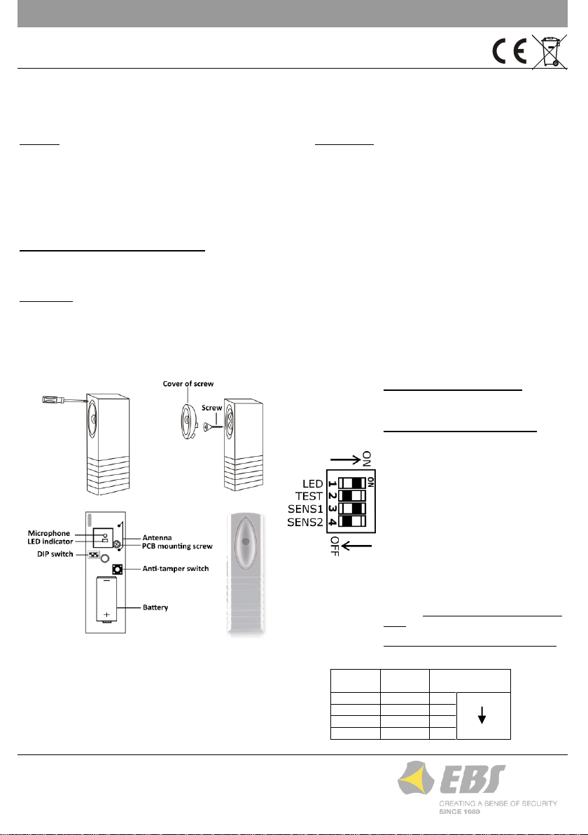
Rys. 2. Uproszczony widok płytki PCB
Rys. 3. DIP switch
Suwak 1 (LED) – Wskaźnik LED:
ON – włączony
OFF – wyłączony (niższy pobór prądu)
Suwak 2 (TEST) – Tryb pracy
ON – Włączony tryb testowy TEST
tryb testowy sygnalizowany jest powolnym
miganiem niebieskiej diody LED; podczas
wykrycia dźwięku o niskiej częstotliwości
czerwona dioda zamiga powoli, przy wykryciu
wysokiej dioda zamiga szybko (tryb ten
powoduje szybsze rozładowanie baterii);
zaleca się, aby test czujki wykonać przy
użyciu ogólnodostępnych testerów zbicia
szyby emitujących dźwięki o wysokiej
częstotliwości (szybkie miganie czerwonej
diody LED w czujce);
OFF – Normalny tryb pracy czujki
alarmy strefy kontrolowanej przez czujkę
wysyłane są do centrali nie częściej niż raz na
3 minuty; podczas normalnej pracy czujka
powinna być ustawiona na ten tryb;
Suwaki 3, 4 (SENS) – Poziomy czułości
Tab. 1. Pozycje suwaków określających poziom czułości czujki
Suwak 3
(SENS1)
Suwak 4
(SENS2)
Poziom czułości
ON
ON
1
niski
wysoki
OFF
ON
2
ON
OFF
3
OFF
OFF
4
Rys. 1. Schemat demontażu obudowy
PL
GB-10 Bezprzewodowa czujka zbicia szyby
Czujka GB-10 wykrywa zbicie szyby ze szkła zwykłego, hartowanego oraz laminowanego. Czujka analizuje docierające do niej sygnały
dźwiękowe pod kątem niskich i wysokich częstotliwości. Te pierwsze generowane są przy uderzeniu w szybę, natomiast te drugie przy
jej stłuczeniu. Dopiero po wykryciu obydwu sygnałów (jeden po drugim) czujka wysyła alarm do centrali. Taki mechanizm detekcji
pozwala wyeliminować fałszywe alarmy podczas przypadkowych uderzeń w szybę. Czujka GB-10 współpracuje z centralą CPX230NWB.
Dodawanie czujki do centrali
Otwórz pokrywę czujki. Wprowadź bezprzewodową centralę alarmową w tryb programowania czujek. Podczas oczekiwania centrali
na sygnał z czujki bezprzewodowej wciśnij przycisk sabotażowy. Po upewnieniu się, że urządzenie zostało poprawnie dodane. Załóż
pokrywę czujki i zabezpiecz ją wkręcając śrubę.
Instalacja
Czujkę należy zamontować naprzeciwko chronionej szyby w odległości do 7m.
Pomiędzy czujką a szybą nie powinno być żadnych obiektów, mogących stanowić przeszkodę dla sygnałów akustycznych
pochodzących od chronionej szyby.
Nie należy montować czujki na tej samej ścianie co chroniona szyba, w rogach potęgujących efekt echa, ani w pobliżu silnych
źródeł hałasu (syren, dzwonków).
Bliskość dużych metalowych obiektów, pól magnetycznych, albo urządzeń wysokiego napięcia może spowodować zakłócenia
transmisji danych do centrali alarmowej. Po instalacji czujki należy sprawdzić poprawność jej komunikacji z centralą.
GB-10_manual_PL_EN_ES_PT_v1.2
EBS Sp. z o. o.
ul. Bronisława Czecha 59
04-555 Warszawa, POLSKA
Wsparcie techniczne: +48 22 51 88 477
E-mail: support@ebs.pl
Strona internetowa: www.ebssmart.com
Features
4 sensitivity level
Low power consumption
Supervisory signal every 15 minute (normal working mode)
Tamper signal if open cover and detachment from the wall
Battery status control (low-power signal at 2.5 V)
Battery lifetime 2-3 years (lifetime is approximate)
Max transmission distance 300 m (open air)
Protection against incorrect battery polarity
Specification
Operation voltage:
Standby current:
Alarm current:
Transmission frequency:
Operation temperature:
Storage temperature:
Dimensions:
Battery:
3 V
<60 uA
20 mA
433,92 MHz
-10 ~ 50°C
-20 ~ 60°C
85x26x33 mm
lithium, CR123A
Fig. 2. Simplified PCB diagram
Fig. 3. DIP switch
Slider 1 (LED) – LED indicator:
ON
OFF – lower current consumption
Slider 2 (TEST) – Operating mode
ON – TEST mode active
The activation of the test mode is indicated
by slow blinking of the blue LED. After
detecting a low frequency sound, the red
LED will blink slowly, after detecting a high
frequency sound, the LED will blink quickly
which drains the battery faster. It is
recommended to test the detectors using
commercially available glass break testers
which produce high frequency sounds
causing the red LED on the detector.
OFF – Normal mode
it means, that detections (alarms) in the
area controlled by the sensor are sent to
control panel not more than once in 3
minutes; the detector should be set in this
mode;
Sliders 3, 4 (SENS) – Sensitivity levels
Tab. 1. DIP switch settings and corresponding sensitivity levels
Slider 3
(SENS1)
Slider 4
(SENS2)
Sensitivity level
ON
ON
1
low
high
OFF
ON 2 ON
OFF 3 OFF
OFF
4
Fig. 1. Cover removal diagram
EN
GB-10 Wireless glass break detector
The GB-10 detector works with ordinary, tempered and laminated glass plates. The detector picks up sounds and analyses them for
extremely low and high frequencies. Low frequency sound occurs when the glass is hit and high frequency sound occurs when the
glass shatters. The detector sends an alarm to the control panel only when these two sounds are detected one after the other. Using
this detection mechanism prevents false alarms during accidental impacts on the window. GB-10 is compatible with CPX230NWB
control panel.
Pairing a detector with the control panel
Open the detector's cover. Switch the wireless control panel to detector programming mode. With the control panel in detecting
mode, press the Anti-tamper button. Make sure that your wireless detector has been successfully paired. Install the detector’s cover
and secure it with the screw.
Installation
Install the detector in front of the glass at the maximum distance of 7 m.
There should be no obstacles preventing sound waves from the glass from reaching the detector.
Do not install the detector on the wall with the glass being monitored, in the corners as it amplifies echo and near a str ong noise
sources (such as sirens, alarm bells, etc.).
Installing in a location near metallic objects, magnetic fields or high voltage equipment might impair data transmission to the
control panel. After installing, check the correct communications with the control panel.
GB-10_manual_PL_EN_ES_PT_v1.2
EBS Sp. z o. o.
59 Bronislawa Czecha St.
04-555 Warsaw, POLAND
Technical support: +48 22 51 88 477
E-mail: support@ebs.pl
Webpage: www.ebssmart.com
 Loading...