

Page 1

EBS-6100
®
EBS
Ink-Jet Systems
USER'S MANUAL
Page 2

Page 3
®
EBS
Ink-Jet Systems
INDUSTRIAL INK-JET PRINTER
EBS-6100
USER’S MANUAL
VERSION 20070529#20.5
EBS Ink-Jet Systems GmbH
Alte Ziegelei 19-25, D-51588 Nümbrecht
+49 (0)2293 / 939-0
Fax +49 (0)2293 / 939-3
http://www.ebs-inkjet.de
Page 4

EBS-6100 Printer User's Manual
EBS
Ink-Jet Systems
®
© 2000 - 2007 EBS Ink-Jet Systems GmbH, D-51588 Nümbrecht
2
20070529#20.5
Page 5

®
EBS
Ink-Jet Systems
EBS-6100 Printer User's Manual
TABLE OF CONTENTS
1. GENERAL INFORMATION ..................................................................................7
1.1. APPLICATION .....................................................................................................................7
1.2. PRINCIPLE OF OPERATION ................................................................................................10
2. INSTALLING THE PRINTER..............................................................................11
2.1. SAFETY REQUIREMENTS ...................................................................................................11
In the case of accident ….....................................................................................11
2.2. POWER SUPPLY REQUIREMENTS.......................................................................................12
Mains Requirements.............................................................................................12
2.3. INSTALLING THE PRINTER .................................................................................................12
2.3.1. Standard and Optional Accessories ..........................................................................12
2.3.2. Preparatory Steps ........................................................................................................13
2.3.3. Removing transport protections ................................................................................14
2.3.4. Connections..................................................................................................................15
2.3.5. Connecting bottles of ink and solvent.......................................................................16
2.4. REMOVING THE HEAD CASING............................................................................................16
3. STARTING THE PRINTER................................................................................. 17
3.1. SWITCHING THE PRINTER ON ............................................................................................18
3.2. SWITCHING THE PRINTER OFF...........................................................................................18
3.2.1. Switching the Printer Off in the Regular Mode .........................................................18
3.2.2. Switching the Printer Off in the Emergency and Service Modes............................19
4. OPERATING THE PRINTER.............................................................................. 20
4.1. CONTROL PANELS............................................................................................................20
4.1.1. External Panel...............................................................................................................20
4.1.2. Internal Panel................................................................................................................22
4.2. OPERATING THE PRINTER WITH THE CONTROL MENU .......................................................24
4.3. PRINT HEAD STATUS........................................................................................................27
4.4. CONTROLLING THE PRINTER .............................................................................................29
4.4.1. Text Files.......................................................................................................................29
4.4.1.1. General Information on Text Files ...........................................................................29
WORD PROCESSOR - A Description of Control Keys........................................31
4.4.1.2. Opening and Editing a New Text File ......................................................................31
Subfile Type: Text - ASCII Characters .................................................................32
Subfile Type: Graphics..........................................................................................34
GRAPHICS PROCESSOR - A Description of Function Keys ..............................35
Subfile Type: BAR CODE ........................................................................................35
Subfile Type: TEXT NAME.......................................................................................37
4.4.1.3. Editing an Existing Subfile .......................................................................................37
4.4.1.4. Copying and Editing a Text File...............................................................................38
4.4.1.5. Deleting a Text File..................................................................................................38
4.4.1.6. Deleting the File Library...........................................................................................38
4.4.1.7. Accessing the File Library........................................................................................38
4.4.1.8. Linking File Names with Parameter-Block Names ..................................................39
4.4.1.9. Using the Password.................................................................................................40
Defining a User Password ....................................................................................40
Enabling the User Password ................................................................................40
Changing the User Password...............................................................................40
20070529#20.5
3
Page 6

EBS-6100 Printer User's Manual
Deleting the User Password.................................................................................41
4.4.1.10. Using Special Registers...........................................................................................41
Object Counters....................................................................................................42
Date and Time ......................................................................................................42
Universal Counter.................................................................................................43
Universal Date and Time......................................................................................48
Expiry Date Registers...........................................................................................49
Special Channel Data...........................................................................................50
4.4.2. Using Print-Parameter Blocks ....................................................................................50
4.4.2.1. Creating and Editing a New Parameter Block .........................................................51
Modifying Parameters...........................................................................................51
4.4.2.2. Editing Existing Blocks of Parameters.....................................................................52
4.4.2.3. Copying and Editing Blocks of Parameters .............................................................52
4.4.2.4. Deleting a Block of Parameters ...............................................................................52
4.4.2.5. Deleting the Parameter-Block Library......................................................................53
4.4.2.6. Accessing the Parameter Block Library...................................................................53
4.4.3. Printing..........................................................................................................................54
4.4.3.1. Stopping the Printing ...............................................................................................54
4.4.3.2. Starting the Printing .................................................................................................54
4.4.3.3. Quick Stopping the Printing .....................................................................................55
4.4.3.4. Suspending printing, editing the text and resuming the printing..............................56
4.4.3.5. Print Parameters......................................................................................................56
Modifying Print Parameters ..................................................................................57
Vertical Direction ..................................................................................................57
Initial Distance ......................................................................................................57
Number of Repetitions..........................................................................................58
Distance Between Overprints...............................................................................58
Horizontal Direction ..............................................................................................58
Print Height...........................................................................................................59
Date Offset ...........................................................................................................59
Counter Increment................................................................................................59
Row Repetition .....................................................................................................59
Print-Rate Mode ...................................................................................................60
Print Rate..............................................................................................................60
Interleaving ...........................................................................................................60
Timing Mode.........................................................................................................60
Print Resolution ....................................................................................................61
Travel Speed ........................................................................................................61
Number of Pulses Generated by External Encoder .............................................61
4.4.3.6. Saving Current Parameters in a Block ....................................................................61
4.4.3.7. Monitoring the Counting...........................................................................................62
Accessing Object Counters ..................................................................................62
Modifying Object Counters ...................................................................................63
4.4.3.8. Monitoring the Print Rate .........................................................................................63
4.4.3.9. Printing with the Use of a Code Switch ...................................................................64
4.4.3.10. Viewing Files on the Terminal Display.....................................................................64
4.4.4. Servicing the Head.......................................................................................................65
4.4.4.1. Service Mode...........................................................................................................65
4.4.4.2. Sucking Ink/Solvent .................................................................................................65
4.4.4.3. Closing and Opening the Ink Valve .........................................................................65
4.4.4.4. Turning the Head off Quickly ...................................................................................66
4.4.4.5. Turning the Ink Flow on ...........................................................................................66
4.4.4.6. Turning the Head off ................................................................................................67
4.4.4.7. Turning the Flow of Solvent On ...............................................................................67
4.4.4.8. Adjusting the Ink Jet Path ........................................................................................67
4.4.4.9. Switching the Stroboscope Over .............................................................................71
4.4.4.10. Monitoring High Voltage during Printing ..................................................................71
4.4.4.11. Defining Some Print Parameters by Measuring Conveyor Travel Speed ...............72
4.4.4.12. Other Commands ....................................................................................................72
4.4.5. Auxiliary Commands....................................................................................................72
EBS
Ink-Jet Systems
®
4
20070529#20.5
Page 7

®
EBS
Ink-Jet Systems
4.4.5.1. System Data ............................................................................................................72
4.4.5.2. Accessing Alarm Messages.....................................................................................73
4.4.5.3. Clearing Alarms .......................................................................................................73
4.4.5.4. Accessing Error Reports..........................................................................................73
4.4.5.5. Setting Date and Time .............................................................................................73
4.4.5.6. Viewing Printer Operation Time...............................................................................74
4.4.5.7. Selecting a Language ..............................................................................................74
4.4.5.8. Releasing Protections..............................................................................................75
4.4.6. Ink and Solvent Bottle Monitoring System................................................................76
4.4.6.1. Checking the Validity Date.......................................................................................78
4.4.6.2. Printer Operation Time vs. Solvent Consumption Time Limit..................................79
4.4.6.3. Accessing Ink Monitoring System Data ...................................................................79
4.4.6.4. Checking How Many Text Files Can be Printed with 1 litre of Ink...........................79
4.4.6.5. Printer Operation Problems During the Replacement of Ink and Solvent
4.5. ALARMS, ERRORS AND INDICATIONS.................................................................................81
4.5.1. Clearing Alarms............................................................................................................87
4.6. ADJUSTING THE PRINT RATE.............................................................................................87
4.6.1. Internal Generator ........................................................................................................87
4.6.2. Shaft-encoder ...............................................................................................................88
4.6.3. Defining the Maximum Print Rate for a Given Text File ...........................................90
4.6.4. Information for advanced users .................................................................................91
4.6.5. Problems with reaching the maximum print rate when a shaft-encoder is
used ...............................................................................................................................92
4.6.6. The Maximum Print Rate vs. Resolution Settings ....................................................94
General Information..............................................................................................76
Replacing the Bottle of Ink (Solvent) ....................................................................77
Bottles ......................................................................................................................81
Ink Monitoring System Flow Diagram...................................................................81
EBS-6100 Printer User's Manual
4.7. SYNCHRONIZING PRINT HEADS .........................................................................................95
5. EXAMPLES OF HOW TO OPERATE THE PRINTER .......................................96
5.1. HOW TO PRINT THE FIRST SAMPLE TEXT FILE ...................................................................96
5.2. CREATING AND PRINTING VARIOUS TEXT FILES .................................................................98
5.2.1. How to Print the Current Date and Time....................................................................98
5.2.2. How to Print Consecutive Numbers...........................................................................99
5.2.3. How to Print Expiry Date ...........................................................................................100
5.2.4. How to Print Logos ....................................................................................................101
5.2.5. How to Print a Bar Code ............................................................................................102
5.2.6. How to Print a Complex Subfile................................................................................103
6. SERVICE AND MAINTENANCE...................................................................... 105
6.1. ROUTINE MAINTENANCE..................................................................................................105
6.2. CHECKING THE ADJUSTMENTS ........................................................................................106
6.3. WHEN PROBLEMS ARISE DURING OPERATION OR SERVICE ..............................................107
6.3.1. The printer cannot be started ...................................................................................107
6.3.2. Misaligned jet of ink...................................................................................................107
6.3.3. Clogged nozzle - cleaning the nozzle.......................................................................108
6.3.4. No nominal ink pressure can be generated by the pump......................................110
6.3.5. Occluded Ink Filter in the Gun..................................................................................110
Replacing the Main Ink Filter ..............................................................................110
Replacing Ink Filter Inside the Gun ....................................................................112
Replacing air filter element in the electronic chamber ventilation system..........113
6.3.6. Reduced partial vacuum............................................................................................115
6.3.7. No flow of solvent in the head ..................................................................................116
6.3.8. The lower part of the print is missing ......................................................................116
6.3.9. Some vertical rows of the print are spaced widely.................................................117
20070529#20.5
5
Page 8

EBS
EBS-6100 Printer User's Manual
6.3.10. Irregular defects of print quality...............................................................................118
6.3.11. Slopping, rippled or jagged print..............................................................................118
6.3.12. Names of text files in the library are changed - the battery is discharged ..........119
6.4. HOW TO CONTACT THE SERVICE POINT...........................................................................119
Ink-Jet Systems
7. STORAGE AND TRANSPORTATION............................................................. 121
7.1. STORING THE PRINTER ...................................................................................................121
7.2. TRANSPORTING THE PRINTER .........................................................................................124
8. TECHNICAL SPECIFICATIONS ...................................................................... 125
9. LAYOUT OF CYRILLIC CHARACTERS ON THE PRINTER’S TERMINAL
KEYPAD...........................................................................................................128
10. LAYOUT OF ARABIC CHARACTERS ON THE PRINTER’S TERMINAL
KEYPAD...........................................................................................................129
Index......................................................................................................................130
®
Dear User,
This Manual contains very useful information on how to operate your InkJet Printer. Please read this Manual carefully.
This edition of the document includes most of the changes introduced to the EBS
printers for software version 21_1C and the descriptions contained therein
correspond to the printers that are equipped with this software version.
As the machine and options can be customised, the product delivered to you
depends on your specific order. Therefore some descriptions or illustrations may
differ slightly from your equipment. As we need to keep pace with new
technological advancement, we reserve the right to introduce changes in the
design and technical solutions adopted. In view of the above, no data,
illustrations or description shall make grounds for any claims. Should your printer
be equipped with options that are not described or illustrated in the Manual or
should you have additional queries after having read the Manual, please contact
any EBS Ink-Jet Systems representative for more information.
6
20070529#20.5
Page 9
EBS
Ink-Jet Systems
®
EBS-6100 Printer User's Manual
Paragraph 1 - General Information
1. General Information
NOTE:
There are warning and information signs on the right or left hand-side margins of some pages to
attract user’s attention to messages that are provided next to them. They are the following signs:
!
!
Information signs indicating:
• that the actions described should be taken carefully,
• additional, printer-specific option and features,
• untypical behaviour of the unit,
• other hints.
A warning not to take the action that might have a critical impact on the
proper operation of the unit. It requires the user to follow closely the
instructions given therein.
A sign informing that the installation or service operation can be performed by
the user who does not need to be qualified for servicing EBS equipment.
EBS
A sign informing that the installation or service operation should be performed
by the user who is qualified for servicing EBS equipment.
The Manufacturer reserves the right to introduce changes whose description may not
!
be provided in this manual.
The Manufacturer shall not be liable for any damages resulting from the failure to follow
the instructions or consequences of editorial or publishing errors within the
instructions.
1.1. Application
EBS-6100 is a non-contact ink-jet printer designed for putting print on objects of
various types, moving for example, on a factory conveyor. The printer provides clear
and firm overprints on materials such as:
• paper and cardboard,
• plastics,
• fabric,
• leather and leatherette,
• wood and wood-like products,
• glass and ceramic products,
• metal surfaces of any type, etc.
Short description of the printer:
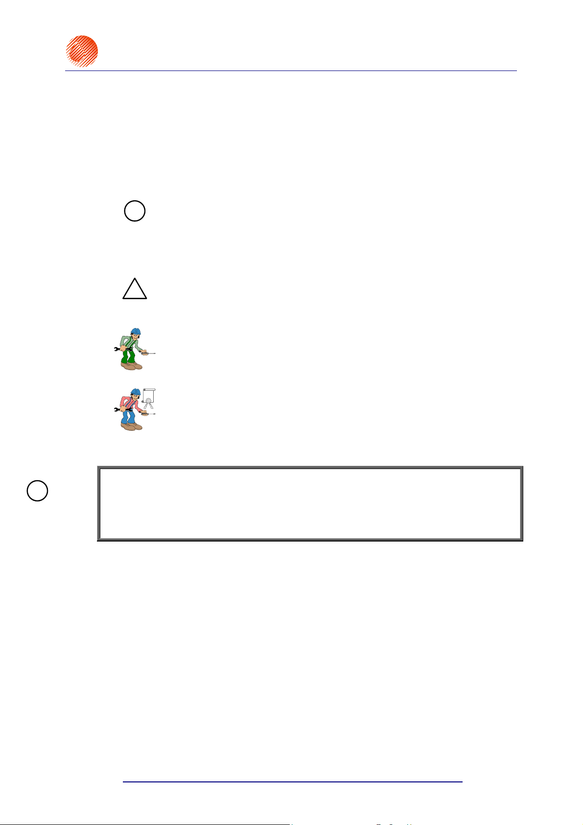
The unit is equipped with one print head of small outer dimensions.
20070529#20.5
7
Page 10
EBS-6100 Printer User's Manual
Paragraph 1 - General Information
The head produces print varying between 1.5 and 14 mm in height.
The head can be set at any position.
The head is connected with the controller via a 4 m long flexible cord as standard.
435
EBS
Ink-Jet Systems
®
Fig. 1.1.1.
Printing capabilities:
• texts composed of small and capital letters out of various matrices, also printed in
boldface or rotated,
300
40
151
202
4000
8
• several lines of text printed during a single run of an object in front of the print
head: a maximum of four lines (with 1-dot space between the lines for the 7x5
matrix) or six lines (with no space between the lines for the 5x5 matrix), with a
maximum print height of 32 dots,
4
lines
(7x5)
5
lines
(5x5)
6
lines
(5x5)
• diacritical national characters,
20070529#20.5
Page 11
EBS
Ink-Jet Systems
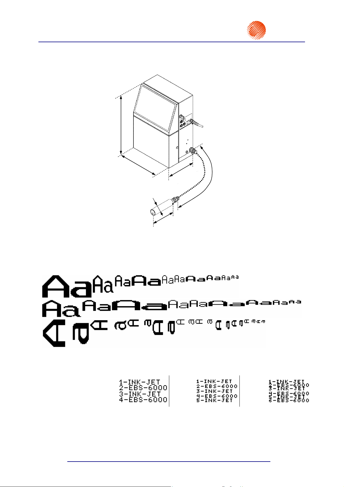
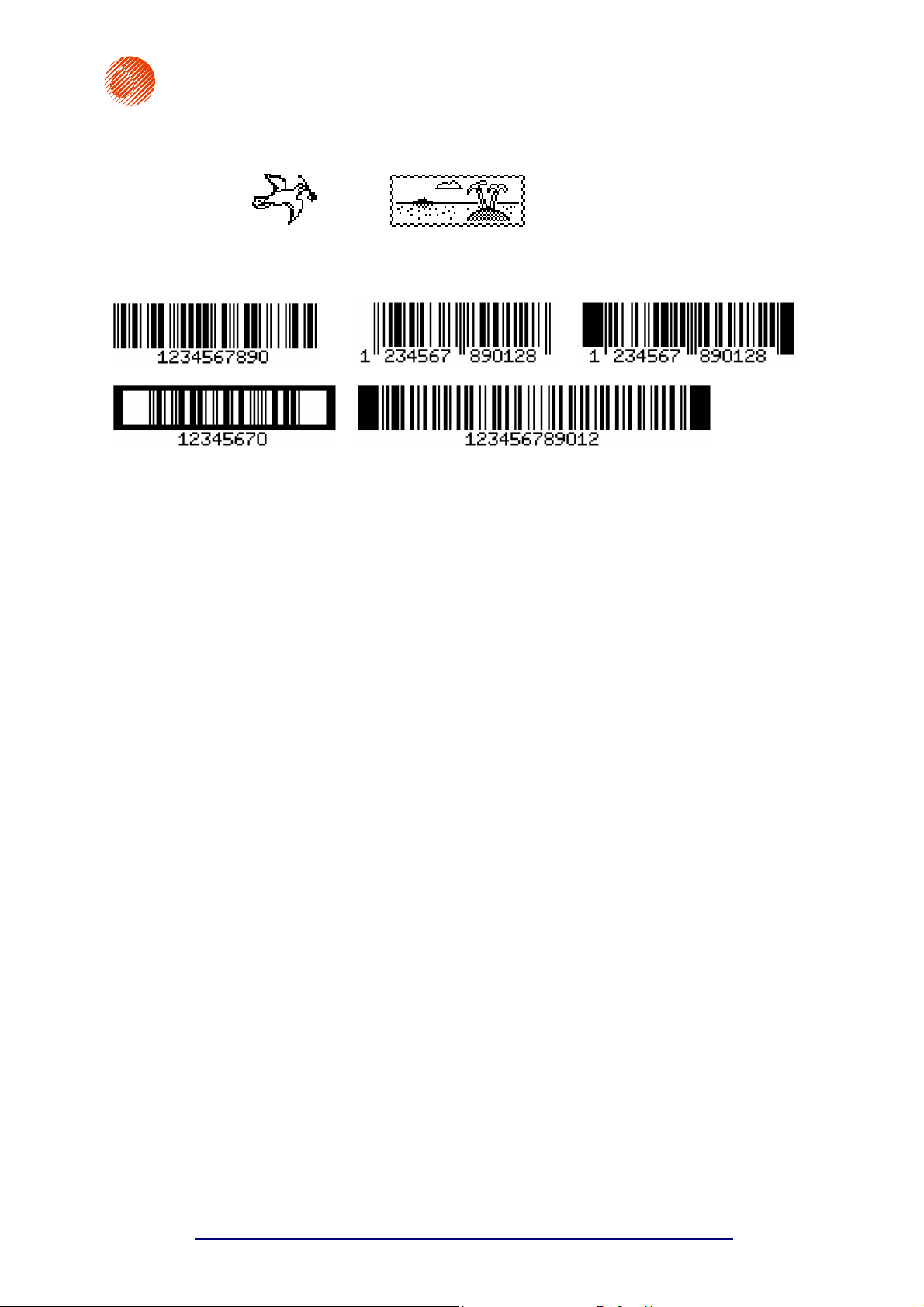
• graphics – a built-in set of ready-to-use graphic symbols and a tool-kit for creating
• bar codes of various kinds, printed in a regular way or in reverse, with or without
• variable data - such as current date, warranty expiration date, current time,
®
user-defined graphics,
a numerical caption; an option of introducing on-going changes to the digital
contents of the code (bar code as an incremental or decremental counter),
ascending and descending numbering (counters), any types of data, which are
transferred from a PC or external devices (via an optional special channel), as
required and arranged by the user.
EBS-6100 Printer User's Manual
Paragraph 1 - General Information
Texts to be printed can be input or modified easily with the use of a built-in terminal, an
external code switch or a PC (via RS-232C or RS-485 interface).
An optional PC can be connected in order to:
• control the operation of one printer via the EdGraf program,
• allow a number of EBS printers of various types, linked together into a network, to be
controlled from one computer via the InkNet program.
Objects to be labelled are detected by a photo-detector.
Fully automatic printer’s operation with the status indication and instructions for
performing service operations.
Full monitoring of ink and solvent bottles. For this reason, bottles designed for different,
incompatible types of EBS printer will not be accepted.
The unit can operate continuously over 24 hours a day.
20070529#20.5
9
Page 12
EBS-6100 Printer User's Manual
Paragraph 1 - General Information
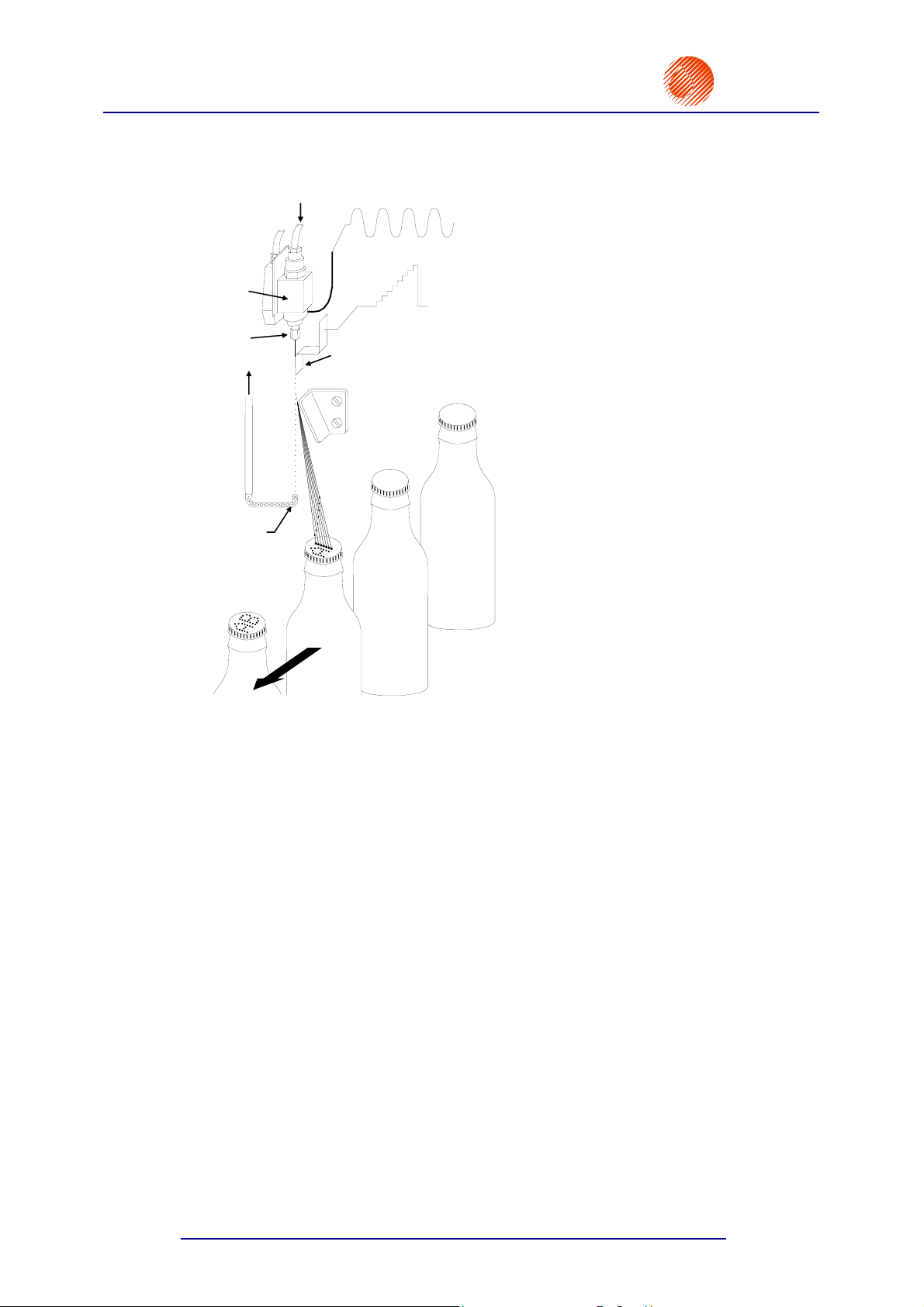
1.2. Principle of Operation
Printing with continuous ink jet printers (CIJ printers).
Ink
Gun
Nozzle
Ink return
Gutter
INK-JET
Charging
electrode
HV deflection
electrode
®
EBS
Ink-Jet Systems
Overprints are produced in the following
way:
• A continuous ink jet is broken into
droplets.
• Then the droplets are charged and
deflected in an electric field.
• Every label consists of drop-wide
vertical rows.
• The droplets are deflected on the
vertical plane. Every droplet within a row
is broken off the continuous jet, then
charged and deflected while passing
under a high-voltage electrode.
• Objects to be labelled move in front of
the print head and vertical rows are
printed one by one to complete the
entire label.
• Uncharged droplets fall into a gutter and
from there are pulled back and returned
to the ink system cylinders.
This method of printing is applied to all CIJ
printers.
Fig. 1.2.1. Labelling with Continuous Ink-Jet printers
The EBS-6100 printer incorporates many unique solutions, including those protected by
patents. Therefore it is in the top flight of units of this type in the world.
10
20070529#20.5
Page 13

®
r
EBS
Ink-Jet Systems
2. Installing the Printer
2.1. Safety Requirements
All efforts have been put into designing this printer carefully and making it safe and reliable.
However, the safe operation of the device is conditioned by the user’s awareness of, and
obedience to the following safety rules and precautions.
EBS-6100 Printer User's Manual
Paragraph 2 - Installing the Printe
The unit should be operated by the staff that has been trained.
the operation of the printer is supervised.
It is recommended that
1. A fire extinguisher designed to extinguish electrical equipment and flammable
solvent fires must be placed within easy reach of the unit.
2. The unit must not be operated in rooms where an explosion hazard exists.
3. No overprints can be made on products whose temperature exceeds 100°C at the
time of printing.
4. No open fire or spark producing devices are allowed in the area where the unit
operates.
5. Power supply cord must be connected to a socket where an earthed pin is used.
The efficiency of earth should comply with the applicable standards. Additionally, in some
cases the printer-housing earth terminal needs to be connected appropriately
(according to the instructions given in section 2.3.4 Connections).
6. As high voltage occurs in the printer, make sure that all manipulations in the
electrical part of the system and inside the head are performed after power has
been switched off.
7. The outlet of the head must not be directed towards persons, animals or accidental
objects during printing in order to avoid splashing anybody or anything with ink.
8. Protective clothes and possibly protective glasses need to be warn by persons
performing any work on the ink system.
!
9. No plastic vessels should be used to do the washing as they collect static electricity.
10. Air contaminated with solvent should be carried away to the outside of the building
11. No ink, solvent or wash-up (or waste fluid remaining after the head has been washed)
WARNING:
Static electricity collected by people (on their plastic clothes or in their hair, for example) may
spark-over to ink or wash-up vessels when they have been left open. The ink and wash-up
are inflammable and may ignite! Therefore, before you approach the open vessels
containing inflammable fluids, discharge static electricity by touching the metal printer
housing or another metal object that is connected to the earth.
In the case of accident …
When ink or solvent spills occur, the spilled fluid should be wiped with a piece of
If the clothing has been splashed, remove it as soon as possible.
20070529#20.5
Metal vessels are recommended.
through a clear duct.
should be left in open vessels as these inflammable fluids may ignite from accidental
sources of fire.
absorbent material and then disposed of in compliance with fire, health and safety at work
(HSE) regulations.
11
!
!
Page 14
EBS-6100 Printer User's Manual
Paragraph 2 - Installing the Printer
Should the eyes or skin get irritated:
EYES need to be rinsed with running water for at least 15 minutes, then you
should see your eye doctor,
SKIN needs to be washed with water and soap.
EBS
Ink-Jet Systems
®
2.2. Power Supply Requirements
Mains Requirements
Standard Option
Supply voltage
Mains frequency
NOTE:
!
• The mains electricity must meet the requirements of the applicable standards. Otherwise
measures need to be taken or devices used to ensure that the proper power is applied to
the printer.
• The mains socket should be equipped with a protective pin properly connected to
earth. The efficiency of the earth needs to comply with the applicable standards.
100-240V (AC)
45-440Hz
90-350V (DC)
DC
2.3. Installing the Printer
2.3.1. Standard and Optional Accessories
As a variety of configurations of EBS-6000 series printers are available, the set of
accessories installed by the user depends on a specific user application. Typical printer
accessories include:
a). Elements and units which are needed for printing in every configuration,
b). Additional and supportive elements and units which are needed for a given configuration
to satisfy user requirements.
List of the accessories that are used most frequently in various printer configurations:
1. Printer (control cabinet and the head),
2. Complete head holder,
3. Photo detector, an optical sensor,
4. Shaft-encoder, a conveyor’s travel-speed indicator,
5. Bottle of ink,
6. Bottle of solvent,
7. Bottle of wash-up,
8. Wash-up spray,
9. Filters:
a). Main ink filter,
b). Ink filter in the head gun,
c). Filter elements for suction tubes in bottles,
d). Air filter,
e). Air filter element for electronic chamber ventilation system.
10. RS232 interface cable to PC,
11. Original rack for EBS-6000 series printers,
12
20070529#20.5
Page 15

®
r
EBS
Ink-Jet Systems
12. Holder for labelling immovable objects manually,
13. Additional external alarm device,
14. Additional external alarm device with conveyor control and stop indication,
15. External code switch,
16. Movable platform with a cable for making overprints manually.
In addition, a variety of special service tools are available, such as:
a). Open end spanner to unscrew the nozzle,
b). Service microscope to adjust ink jet parameters in the head,
c). Service tool: a template for adjusting the HV electrode position,
d). Service tool: a template for adjusting the distance between the gutter and nozzle.
e). Service tool for shaping Ø 3 Teflon pipe tips.
NOTE:
• The above list shall not be considered a specification of accessories (to be) delivered
together with a printer or printing system.
• The list of accessories may vary from country to country.
2.3.2. Preparatory Steps
EBS-6100 Printer User's Manual
Paragraph 2 - Installing the Printe
!
In order to prepare a new or transported printer to operation, you should perform the following
activities:
Place the unit in a room that is free from vibration, shocks, dust, smoke, soil, aggressive
or inflammable vapours and gases.
NOTE: The room shall meet the following requirements:
Environmental conditions: operating temperature from +5°C to +40°C,
relative humidity up to 90% without condensation.
Mechanical requirements: max. vibration 1g at the max. frequency of 10Hz,
max. shocks of 1g over the maximum of 2ms.
Ensure that free and easy access to the
unit is provided.
Place the printer on a 0.7 to 1.1 m high
horizontal table or original rack for
EBS-6000 series printers for
convenience.
Check for mechanical damages to the
unit, head and connecting hose, which
might have been caused during
transportation.
!
Secure the print head holder in a convenient position.
20070529#20.5
Fig. 2.3.2.1.
13
Page 16
EBS-6100 Printer User's Manual
Paragraph 2 - Installing the Printer
Head holder
37 mm
2xM5
Fig. 2.3.2.2. Fixing the standard head holder to a conveyor
Photo detector holder
Head axis
EBS
Ink-Jet Systems
®
Secure the print head in the holder in any required position.
Install the photo detector in clamps fixed to the head holder or in any other place which
would be most suitable for the object under print.
!
NOTE: If conveyor vibration is too strong, it would be better to fasten the head holder
on a stable rack or on a wall, provided that the rack and the wall are not in
contact with the conveyor.
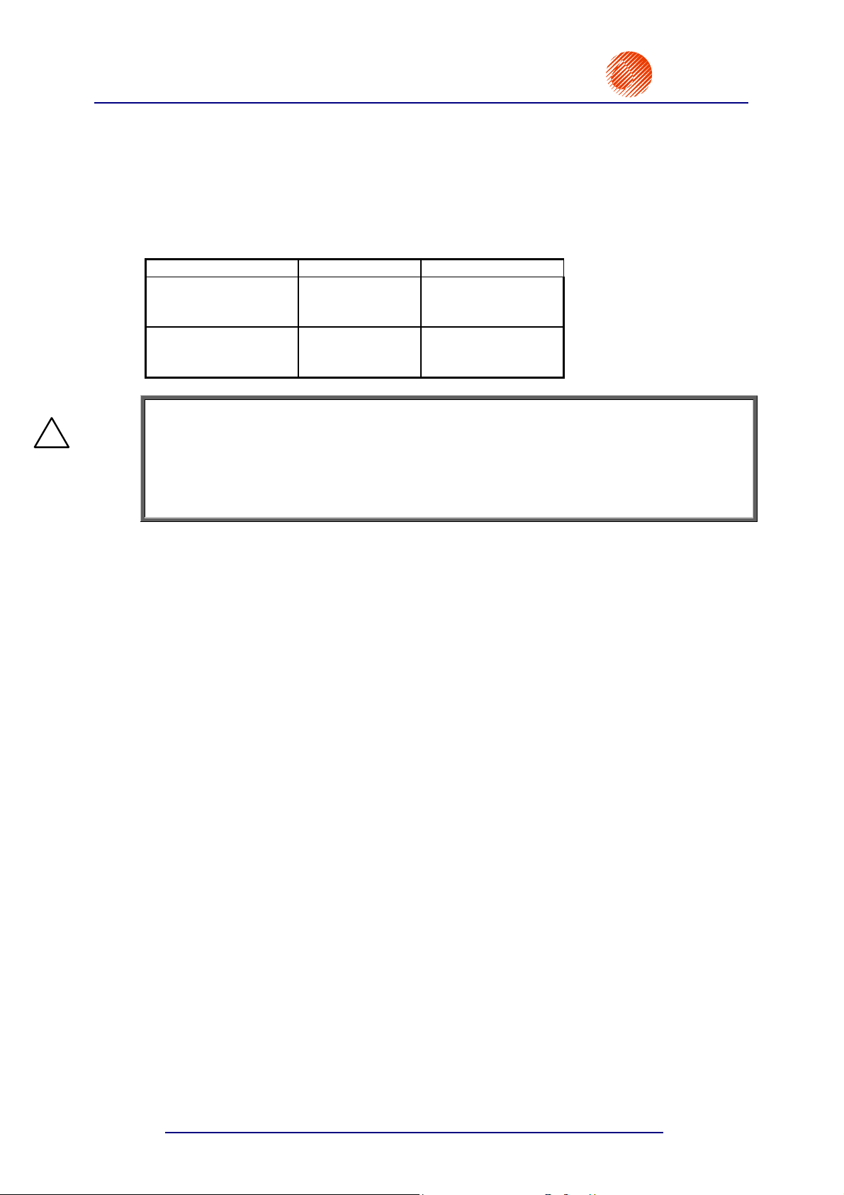
2.3.3. Removing transport protections
The cylinders are protected against spilling the liquid contents in the event the printer tilts or
shakes during transportation. Therefore some of the internal connections are separated,
pipes are removed and the holes are plugged. The protections need to be removed and each
of the connections restored.
1. Remove plugs from the connectors (couplings)
, , .
2. Connect corresponding pipes according to the following diagram.
valve manifold
bottle of ink
V3
VAC
R3
tank
RET
14
R3
air filter
head gutter
Fig. 2.3.3.1. View of connections on tank covers and inside the unit.
20070529#20.5
Page 17
®
r
–
EBS
Ink-Jet Systems
A description of how to reconnect connectors after the unit has been delivered:
• Tank R3: RET - to connect a return pipe in order to transfer ink from the
• Valve manifold: V3 - to connect ink bottle to V3 valve
VAC - to connect the tank to a vacuum pump.
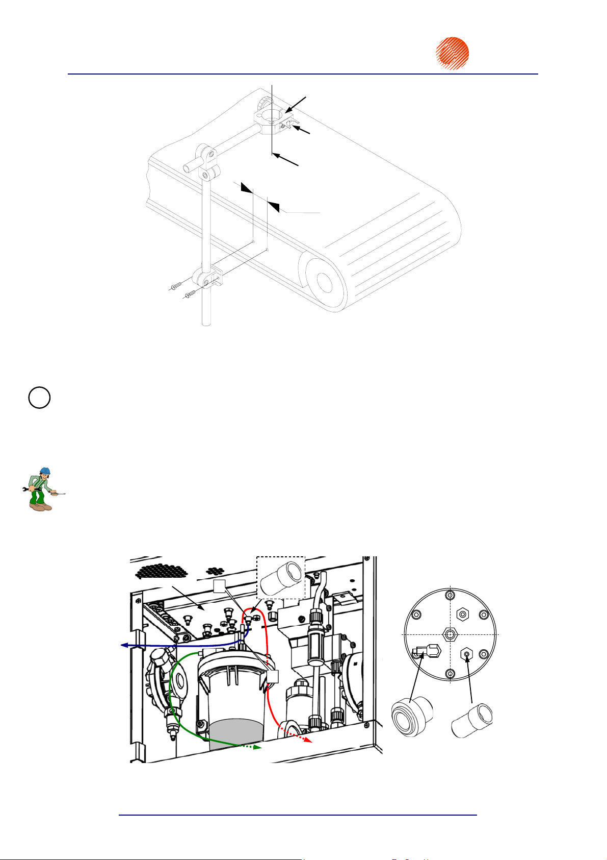
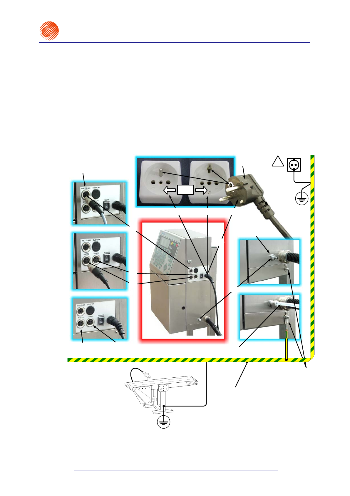
2.3.4. Connections
On putting the printer in place and removing transport protections make the connections
that are shown in the figure below, following the order indicated by the numbers
, .
EBS-6100 Printer User's Manual
Paragraph 2 - Installing the Printe
head gutter back to the tank;
in the valve manifold.
, , , ,
Special-channel interface
connector (to connect a PC)
B
B
or
Mains electricity with an earthing contact
Mains plug
Waste-air pipe
connector
M5
!
B
A
A
Photo detector
socket
Head casing is electrically
connected with an earthed
Fig. 2.3.4.1. Major connections in the EBS-6100 printer
20070529#20.5
conveyor
Shaft-encoder
socket
min. 4 mm hose to vent contaminated air
between points A and B and
Earth bar
between A and C should be
C
Earth terminal
maximum resistance
0.1 Ohm when the mains
plug is out of the mains
socket
the
15
Page 18
EBS-6100 Printer User's Manual
Paragraph 2 - Installing the Printer
2.3.5. Connecting bottles of ink and solvent
1. Insert suction pipes to the bottles of ink and solvent. Check for filters on the pipe tips. The
caps of ink and solvent bottles can be distinquished from each other by the number of
pipes going from the printer's ink system to either cap. The ink bottle cap contains one
pipe whereas the solvent bottle cap - three pipes.
2. Screw the bottles into the caps where the pipes are inserted and place them in a cavity in
the ink system door.
EBS
Ink-Jet Systems
®
!
NOTE:
• Make sure that the original ink and solvent are contained in the bottles. A possible
mistake may result in damage to ink contained in the unit’s containers (due to a change
to the chemical structure of ink) and cause many serious problems.
• Avoid misplacing the bottles of ink and solvent or placing the bottle of solvent
where the bottle of ink should be.
• Different types of ink must not be mixed. Do not add to the bottle any ink whose
shelf life has expired.
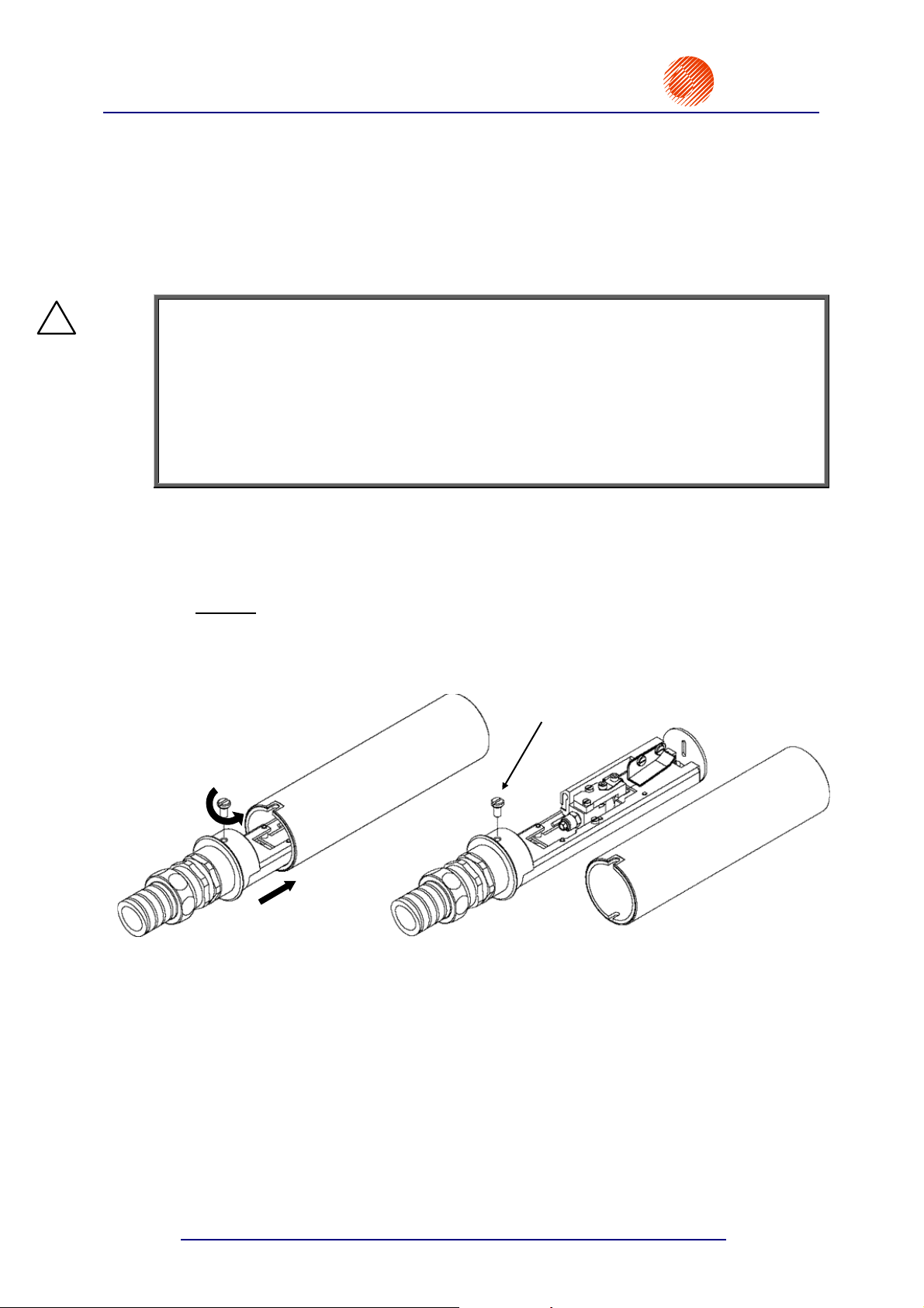
2.4. Removing the head casing
To gain access to inner parts of the head, remove the head from the holder and remove the
casing. The operation involves the following steps:
• Unscrew
• Remove the head from the casing carefully
the fixing screw on the head casing ,
.
The screw secures the head
casing and ensures electrical
contact between the metal
casing and the printer earth
Unscrew in
this direction
Fig. 2.4.1.
16
X
Y
Direction
of removal
Head
casing
20070529#20.5
Page 19
®
r
EBS
Ink-Jet Systems
3. Starting the Printer
EBS-6100 Printer User's Manual
Paragraph 3 - Starting the Printe
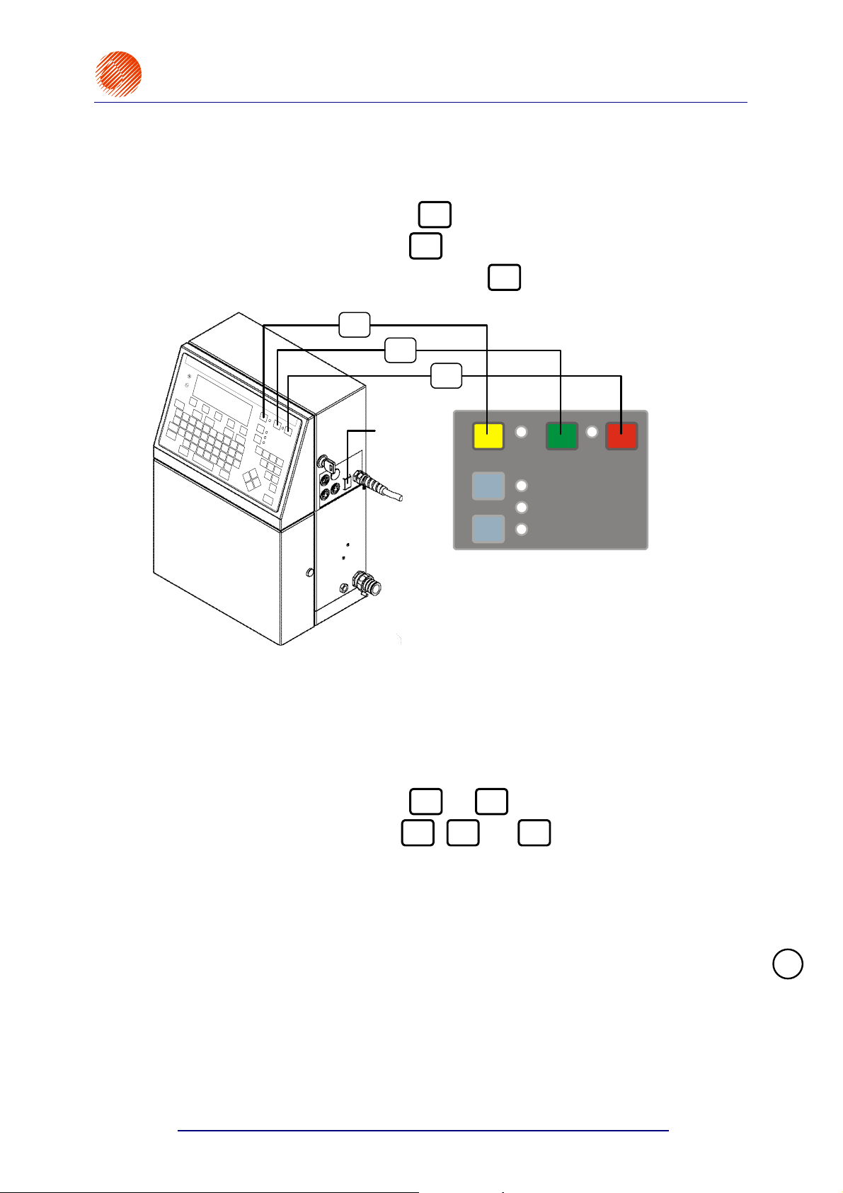
The following key descriptions are used throughout the manual:
ON
OFF
,
OFF
,
CLR.
ALARM
.
• The green ON key is marked with
• The red OFF key is marked with
• The yellow CLR. ALARM key is marked with
CLR.
ALARM
ON
Main power
switch
ERROR
CLR. ALARM
PRINT ON / OFF
READY
INK ON / OFF
OFF
ON
Fig. 3.1.
The EBS-6100 printer is equipped with a power supply with a watch circuit. There are
two power switches that differ from each other over the way mains electricity is switched on or
off:
1. The main (bi-stable) power switch, which separates electrically two power wires
from the mains; it is located on the right-hand side of the unit next to the mains
cord. After the main power switch has been turned on, the printer triggers to the watch
mode and the red lamp between the
2. The electronic power switch (the
ON
ON
designed to turn the printer on and off by changing the printer’s mode from the watch
mode (the lamp emits red light) to the operation mode (the lamp emits green light) and
vice versa. The keys should normally be used to switch the unit on and off.
If it needs to be separated electrically from the mains, the unit should be turned off,
as described in section 3.2 Switching the Printer Off, and then the main power
switch should be turned off.
NOTE: The description below relates to the printer in its watch mode, i.e. with its
main switch in the ON position.
and
,
OFF
OFF
keys comes on.
CLR.
ALARM
and
keys on the external panel)
!
20070529#20.5
17
Page 20

EBS-6100 Printer User's Manual
Paragraph 3 - Starting the Printer
3.1. Switching the Printer On
If all the connections are made properly, then it is enough to press the green
the external panel) (see Fig. 3.1).
Then, the starting procedure is initiated. It involves the following steps:
1. Power voltage is applied and electronic cards are tested.
2. The high voltage module is set to the value that is already stored in the memory (it takes
from a few to a dozen or so seconds).
3. The nozzle is rinsed with solvent (for about 10 seconds).
4. Solvent is sucked out (for about 2 seconds).
5. The flow of ink in the head starts and the printer waits until ink parameters stabilize.
Afterwards, the automatic process of breaking the ink jet into droplets starts, initiating the
phasing procedure and ink viscosity measurement (it takes about 2 minutes).
If no head should work after the printer has been turned on, the turning on should be followed
by the FAST OFF command within the submenu SERVICE. The above mentioned starting
procedure consists of step 2 only. Use the INK ON command to activate the head.
EBS
Ink-Jet Systems
ON
button (on
®
During the starting procedure the red READY lamp (on the internal panel available on the
electronic card, after the upper door has been opened) - see Fig. 4.1.2.2, indicates the
following:
no light - ink is supplied to the head and ink parameters stabilize,
flashing - the ink breaking process stabilizes,
steady light - the head is ready for printing. The START PRINT command can be
selected.
During the entire starting procedure both the parameters and text files can be selected and
modified. If the START PRINT command is selected before the READY lamp comes on, the
command is not executed (the message UNIT NOT ACTIVE is displayed instead). Some
errors may also delay the readiness of the unit for operation by about 2 to 3 minutes. Check
for error indications on the terminal or the internal panel.
If the EBS-6100 printer has not been used for a period of at least 2 weeks, ink pressure
may drop and the following error messages may appear twice or three times after the unit has
been started: INK PUMP TIME-OUT or INK PRESSURE DROP. You can clear the alarm with
CLR.
the yellow
ALARM
key and continue operating the unit as usual.
3.2. Switching the Printer Off
There are several modes of switching the printer off:
Regular mode (to switch the printer off for a period of up to 1 week),
Emergency mode,
Service mode,
Switch-off mode preparing the printer for storage over a longer time (up to 3 months
or longer than 3 months) – for a detailed description refer to 7.1 Storing the Printer.
3.2.1. Switching the Printer Off in the Regular Mode
In order to switch the printer off in the regular mode you just need to press the red
18
(see Fig. 3.1) on the external panel and wait a few minutes for the printer to turn off. Then the
ON
lamp between the
and
SWITCHING THE PRINTER OFF ..... message is displayed on the terminal and the time till
the end of the switching off procedure is counted down in the status window.
OFF
keys changes colour from green to red. The
OFF
key
20070529#20.5
Page 21

r
®
EBS
Ink-Jet Systems
The following processes are involved when the printer is switched off in the regular mode:
Ink is sucked from the ink pipes,
The pipes, gun, nozzle and gutter are rinsed,
The pipes connected to the head are filled with solvent.
NOTE:
If the printer is switched off in the regular mode too often, the ink becomes excessively
diluted and the ink system may be overfilled and then the following message is displayed
to inform you about that:
THE INK SYSTEM CAN BE
OVERFILLED BY MULTIPLE
SWITCHING OFF !!
If you need to switch the unit off for a short time (up to about 1 hour) to perform a service
or other operation, switch it off in the service mode - see section 3.2.2 Switching the
Printer Off in the Emergency and Service Modes.
If the printer needs to be switched off for a longer time (over 1 week), it should be
switched off in accordance with the instructions given in 7.1 Storing the Printer.
EBS-6100 Printer User's Manual
Paragraph 3 - Starting the Printe
3.2.2. Switching the Printer Off in the Emergency and Service Modes
In order to switch the printer off in the emergency mode, press the red
holding it down press and release the yellow
can cut off the supply of electricity to the printer with the main power switch. This type
of switching off is allowed only in the event of an evident printer failure, especially
when the failure to switch the printer off in the regular mode may cause more extensive
or additional damage (such as an ink spill).
NOTE:
On switching the printer off in the emergency mode, do not leave it in the off state for longer
than about 30 minutes. The head may be splashed with ink which may dry. Therefore sprinkle
the nozzle with solvent before you switch the printer off.
You can switch the printer off in the service mode in the same way, as you proceed in the
emergency mode. The service mode is used to switch the printer off quickly (without rinsing)
for a few minutes in order to perform a service operation (see the note below). If the unit
needs to be switched on and off frequently, then the service mode should only be used in
order to prevent ink from getting diluted excessively and the ink system from getting overfilled.
NOTE:
• After the unit has been switched off in the emergency or service modes, wash the inner
part of the head (especially around the gutter) with solvent.
• If you switch on the unit that has been switched off in the service or emergency modes,
the following warning message is displayed on the terminal:
OPERATORS ERROR !!! :
THE HEAD WAS NOT FLUSHED
BEFORE SWITCHING THE PRINTER OFF.
CLR.
ALARM
key (see Fig. 3.1). Or alternatively, you
OFF
key and while
!
!
20070529#20.5
19
Page 22
EBS-6100 Printer User's Manual
Paragraph 4 - Operating the Printer
4. Operating the Printer
4.1. Control Panels
4.1.1. External Panel
EBS
Ink-Jet Systems
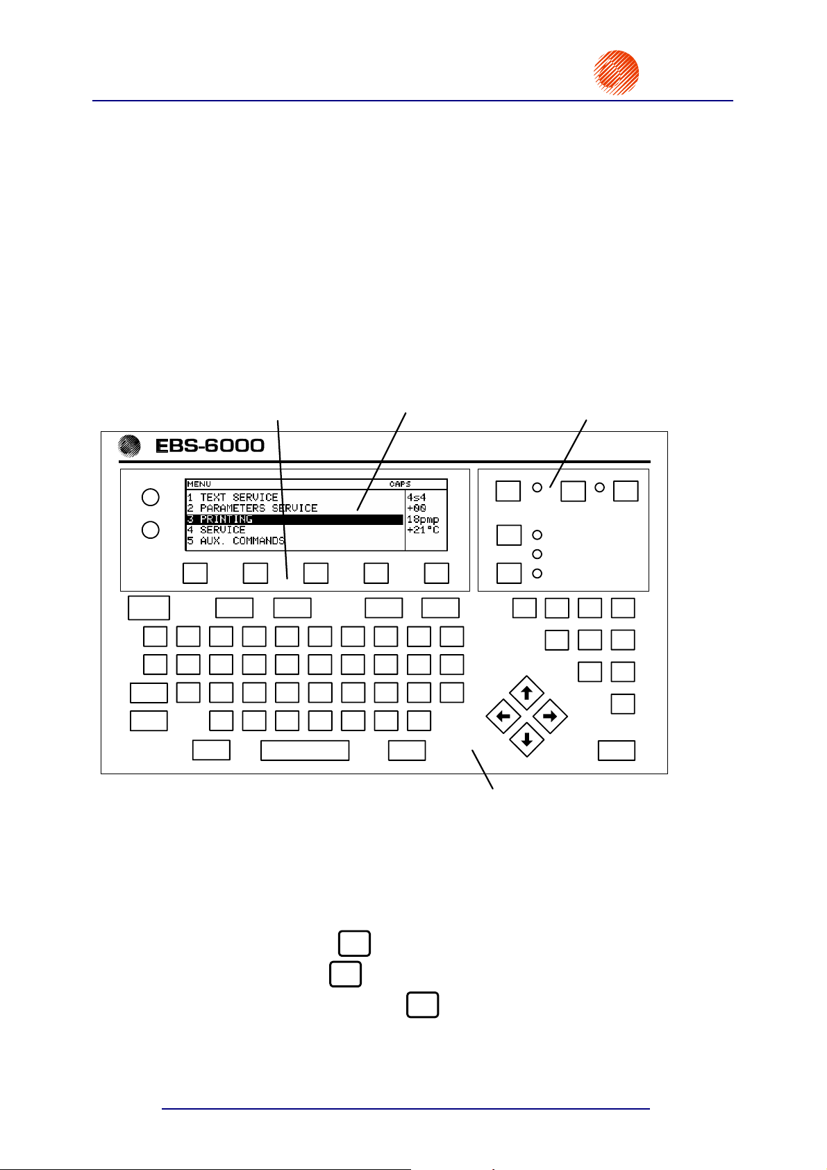
®
Terminal
is used by the operator to communicate with the printer. It helps to control the printer's
operation, edit text files to be printed and store them in the printer's memory, access and modify
system parameters and monitor the printer's condition. The terminal is located on the external panel
and consists of a graphic display, an alphanumerical QWERTY keypad and contrast-control and
function keys. All terminal features are described further on in this chapter.
+
CONTRAST
–
F1 F2 F3 F4 F5
Esc Insert Delete Par Alt
_
+
-
Q T W R E UY I O P
Caps
Ctrl
[
=
A S D F G H J
4
;
]
X Z
, .
'
BV C
2
? |} : " < >{
K
NM
1
ERROR
CLR. ALARM
!
\/
L
PRINT ON / OFF
READY
INK ON / OFF
@
253 4
1
% ^
ON OFF
$
#
&
*
(
8 0 9
)
7 6
Shift Space Shift Enter
Fig. 4.1.1.1. External panel with the terminal section
1 The main pad contains the following elements:
Keys
• the green ON key
• the red OFF key
• the yellow CLR. ALARM key
• the dark blue PRINT ON/OFF key to start and stop the printing,
• the dark blue INK ON/OFF key to start and stop the flow of ink inside the print
head.
20
ON
- to switch the printer on,
OFF
- to switch the printer off,
CLR.
ALARM
3
- to clear alarms,
20070529#20.5
Page 23
r
EBS
Ink-Jet Systems
LEDs
• the red / green lamp between the ON and OFF keys to indicate the printer’s on or
• the red ERROR lamp next to the CLR. ALARM key to indicate the alarm state,
• the green lamp next to the PRINT ON/OFF key to indicate that the printer is in the
• the yellow lamp next to the READY key to indicate that the head is ready for
• the green lamp next to the INK ON/OFF key to indicate that the flow of ink in the
®
off state,
print mode or is not,
printing,
print head is on or off.
EBS-6100 Printer User's Manual
Paragraph 4 - Operating the Printe
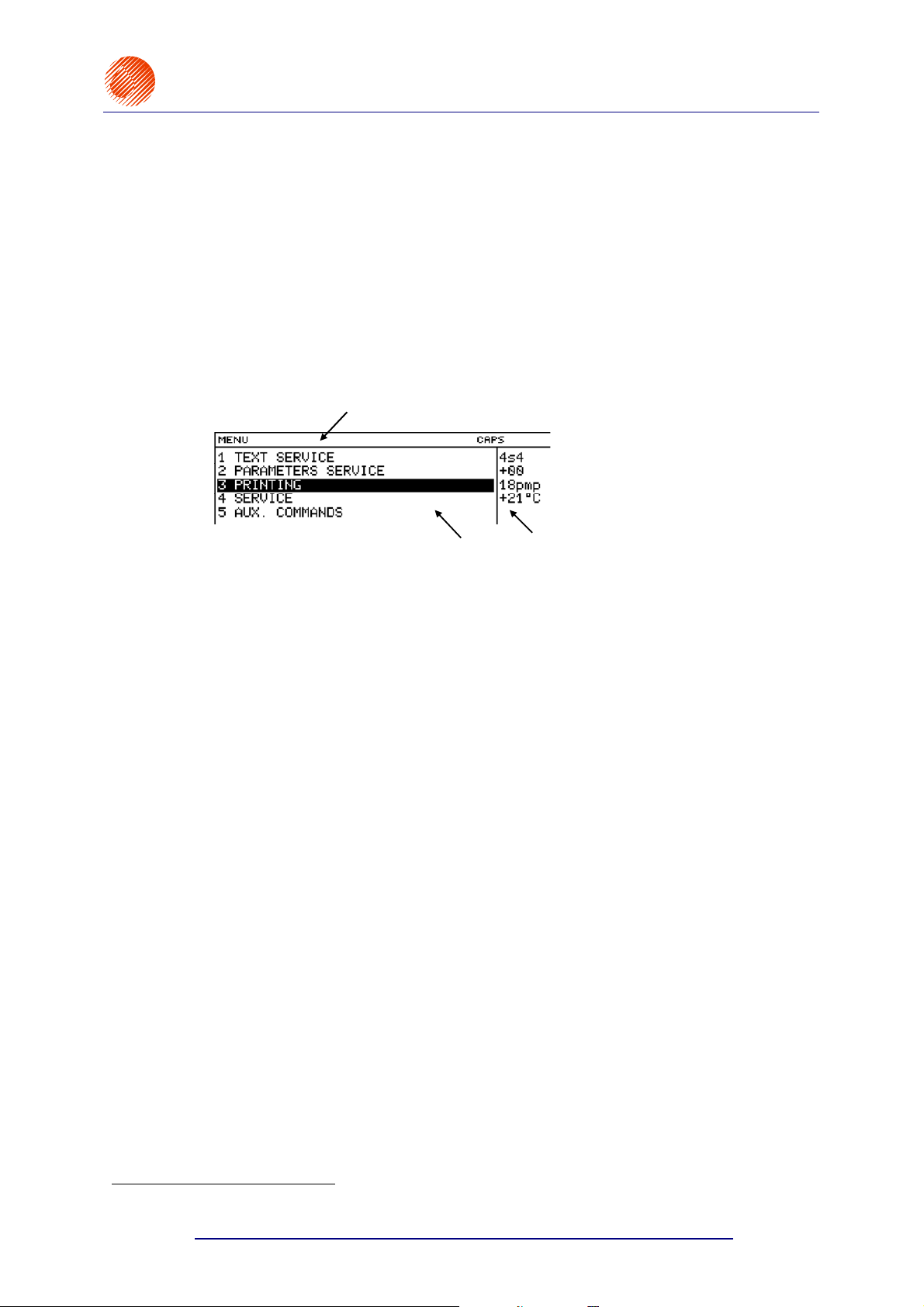
2 Graphic display (the display) with a resolution of 240x64 pixels
divided into independent sections (windows).
a
b
a Terminal status window one line high, contains the following data
(from the left-hand side):
• short 12-character messages (e.g. on the condition of the pen during the
edition of a graphics subfile or the name of a MENU option),
• 3-character typing mode (INSert, OVeRwrite),
• the position of the
lower case letters,
• the indication that the
• coordinates of the graphics cursor (during the edition of graphics).
© key that is used to switch between capital and
Y or « function keys have been pressed,
b Working window five lines high, it is the main display window to show
the control MENU, parameters and messages, to edit text files, etc.
c
1
. The display area is
c Printer status window five lines high, located to the right of the working
window, contains data on the head status for different printer operation modes
- see section 4.3 Print Head Status.
3 Alphanumerical keypad to start control functions and introduce the accompanying
sequences of digits and letters (characters).
The keys are grouped on the terminal keypad according to application.
Group of control keys
Group of numerical keys
1
Pixel - any of the smallest elements that together form a graphical image. It can be on or off.
20070529#20.5
the following keys:
U ¥ ¦ § ¨
© « Y V - and the arrow
keys on a light blue background
¢ ¡ £ ¤ (see Fig. 4.1.1.1).
the following numerical keys: 1, 2, ... , 9, 0.
:
21
Page 24
EBS-6100 Printer User's Manual
Paragraph 4 - Operating the Printer
EBS
Ink-Jet Systems
®
Group of alphabetical keys
All the above specified characters are available immediately after the corresponding
key has been pressed.
Each time you want to type in a character marked in the top left corner of some
keys, press the Y key before the character is selected. This does apply to the
following characters: _ + { } : " < > ? | ! @ # $ % ^ & * ( ).
4 Special function keys comprising:
• contrast control keys,
+
- to increase the contrast, –- to reduce the contrast
F1 F2 F3 F4 F5
•
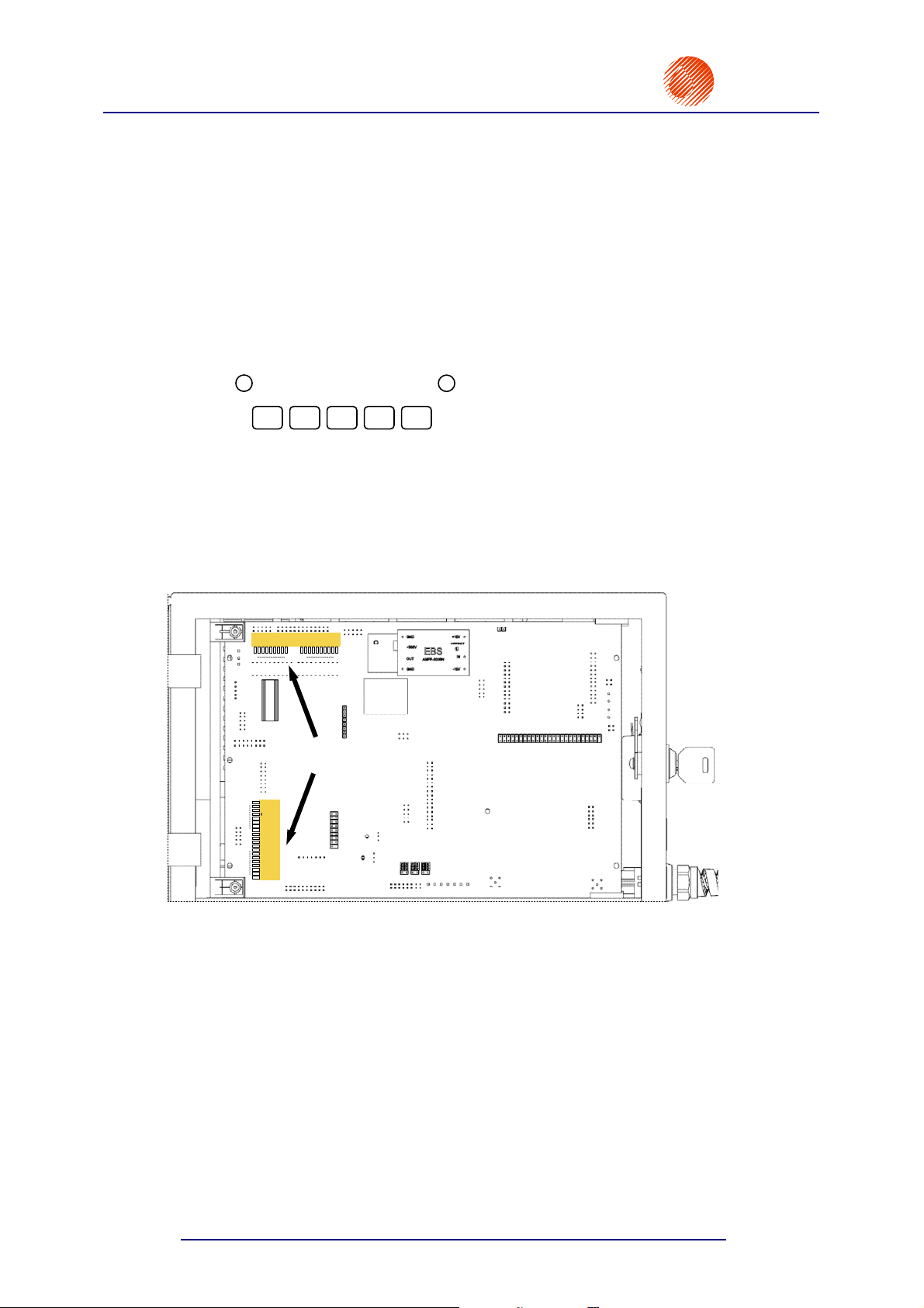
4.1.2. Internal Panel
The internal panel is used to indicate the condition of inner assemblies of the printer,
errors, alarms and failures. The condition, errors, alarms and failures are indicated with a
number of lamps (two rows of light-emitting diodes, L1 - L20, L21 - L39) located on the
printer's main electronics card, that is available after the upper door has been opened (see
Fig. 4.1.2.1).
the letter keys A, B, C, ... , Z, the keys - = [ ] ;
' , . / \ and the
ª key.
function keys to define various additional functions.
/
V91
VAC.
V01
POWER
V92
V82
V12
V81
V11
PREAS-
SURE
V2 A()ALARM
V2VV3V4V5V6
V02
L21
L21 - L39
V7
VX
L39
Internal panel
LEDs
L20
300V ERR.
CHK V. ER.
V1/V7 ERR.
FILL. ERR./
PRESS.DROP
SOLV. BAD
INK LACK
SOLV. LACK
PRESS.LACK
PH. ERR.2
PH. ERR.1
HV2 ON
READY 2
L1 - L20
HV1 ON
READY 1
+VIS (SOLV)
-VIS (INK)
St1
Sb1
St3-OVER
L1
Sb3
Fig. 4.1.2.1. Location of internal panel indication LEDs
22
20070529#20.5
Page 25

r
EBS
Ink-Jet Systems
L20
L1 - L20
L1
®
300V ERR.
CHK V. ER.
V1/V7 ERR.
FILL. ERR./
PRESS.DROP
SOLV. BAD
INK LACK
SOLV. LACK
PRESS.LACK
PH. ERR.2
PH. ERR.1
HV2 ON
READY 2
HV1 ON
READY 1
+VIS (SOLV)
-VIS (INK)
St1
Sb1
St3-OVER
Sb3
EBS-6100 Printer User's Manual
Paragraph 4 - Operating the Printe
A vertical row of lamps L1 - L20 is accompanied by
captures on the right of the LEDs. The lamps can emit
steady light or flicker. The meanings of the two states of
each lamp and the procedure to be followed if a failure
occurs are described in section 4.5 Alarms, Errors and
Indications.
Fig. 4.1.2.2. Error and status lamps emitting red light
300V ERR. +300V voltage failure 0,
CHK V. ER. not used,
V1/V7 ERR. V11(V1) valve failure,
FILL. ERR./
PRESS.DROP ink pressure dropped down below its nominal value (PRESS.DROP),
SOLV. BAD not used,
INK LACK no ink in the bottle,
SOLV. LACK no solvent in the bottle,
PRESS.LACK ink pressure exceeds its nominal value ,
PH. ERR. phasing error in the head,
HV ON this has two meanings:
• the lamp emits steady light - high voltage has been applied to the
head,
• the lamp flickers - HV failure or the failure to keep the voltage at the
required level,
READY this has three meanings:
• no light - the head is not ready for printing, the flow of ink can be
turned on,
• the lamp flickers - ink flow to the head is turned on, the process of
breaking ink into drops stabilizes,
• the lamp emits steady light - ink jet is supplied, the head is ready for
printing,
+VIS (SOLV) the system is refilled with solvent - ink viscosity is greater than the nominal
value,
-VIS (INK) the system is refilled with ink - ink viscosity is smaller than the nominal
value,
St1 not used,
Sb1 not used,
St3-OVER the indication of high ink level in cylinder R3; this has two meanings:
• the lamp emits steady light - cylinder R3 is overfilled
permanently - a failure,
• the lamp flickers- cylinder R3 is overfilled temporarily (e.g. due to ink
surge in the cylinder),
Sb3 the indication of low ink level in cylinder R3,
20070529#20.5
23
Page 26
EBS-6100 Printer User's Manual
Paragraph 4 - Operating the Printer
EBS
Ink-Jet Systems
®
/
V91
VAC.
V81
V11
V01
POWER
V92
V82
V12
V02
L21
Fig. 4.1.2.3. Indication lamps emitting green light
POWER the lamp indicates that a power signal has been applied to keep the
printer’s power supply in the on state,
V01 the indication that electrovalve V0 is turned on to supply ink to the head,
V11 the indication that electrovalve V1 is turned on to suck ink from the head,
PREASSURE the indication that the ink pressure pump is turned on,
V2(A) the indication is not used,
V2V the indication is not used,
ALARM the indication that an alarm is generated (the duplication of the ERROR
lamp on the main pad of the external panel),
V3 the indication that electrovalve V3 is turned on to refill ink from bottle,
V4 the indication that electrovalve V4 is turned on to refill solvent from bottle,
V5 the indication that electrovalve V5 is turned on - underpressure is
generated in the solvent pump to ensure that solvent is taken from solvent
bottle,
V6 the indication that electrovalve V6 is turned on – ink is supplied to the
solvent pump under pressure to rinse the head with solvent,,
V7 the indication is not used,
V91/VAC. the indication that the vacuum pump is turned on,
V92 the indication is not used,
V02 the indication is not used,
V12 the indication is not used,
V81 the indication is not used,
V82 the indication is not used.
L21 - L39
PREAS-
SURE
()
V2 A
ALARM
V2V
V3V4V5V6V7
VX
L39
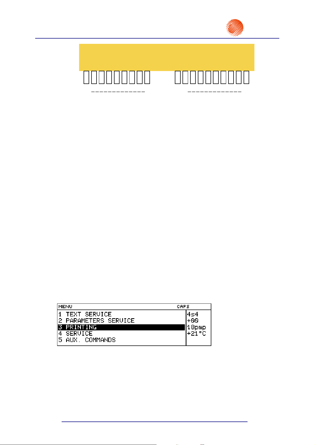
4.2. Operating the Printer with the Control MENU
After the printer has been switched on, the control menu is displayed in the operating
window of the graphic terminal. The MENU has a multilevel tree structure. Commands are
executed directly at the lowest level. The moving from one menu branch to the other involves
no action. Only the execution of a command implies an action in the unit, for example printing,
moving to the word processor, modifying parameter settings, etc.
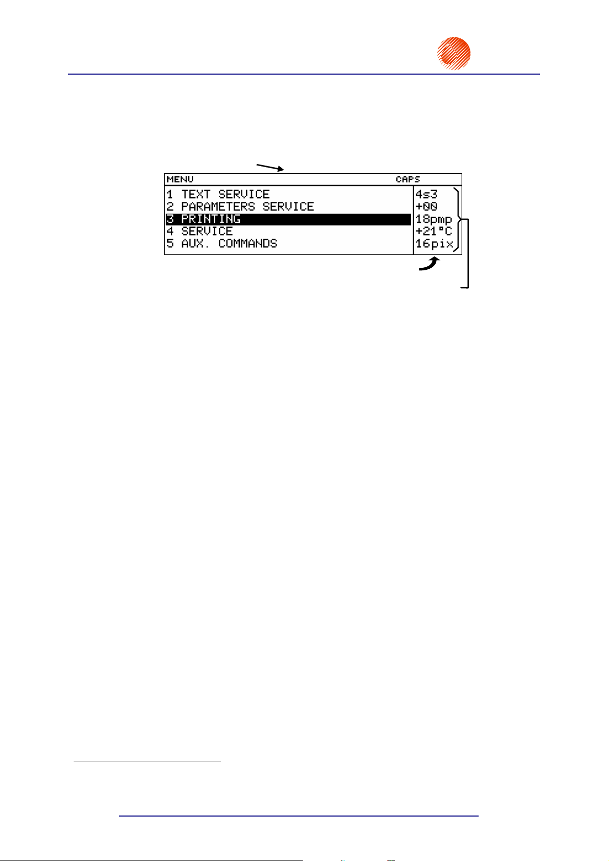
Fig. 4.2.1. View of the primary (main) MENU branch, also called MAIN MENU
The first character (a digit or letter) in each MENU option is a hot key. When this key is
pressed, the cursor bar is immediately positioned on the selected option.
The following keys help you to move along the tree:
£ To move the cursor one menu item upwards.
¤ To move the cursor one menu item downwards.
Y ¢ or Y £ - to move the cursor to the first item.
24
20070529#20.5
Page 27

r
EBS
Ink-Jet Systems
®
EBS-6100 Printer User's Manual
Paragraph 4 - Operating the Printe
Y ¡ or Y ¤ - to move the cursor to the last item.
V To move one level downwards (to the next MENU branch) or to confirm
the selected command for execution.
U To move one level upwards or cancel the selected command. If you press
the U key several times, you are always moved back to the main MENU
level.
NOTE:
After the selection of a command has been confirmed with the V key, it is not always
possible to cancel the command. Some commands are executed immediately.
!
20070529#20.5
25
Page 28
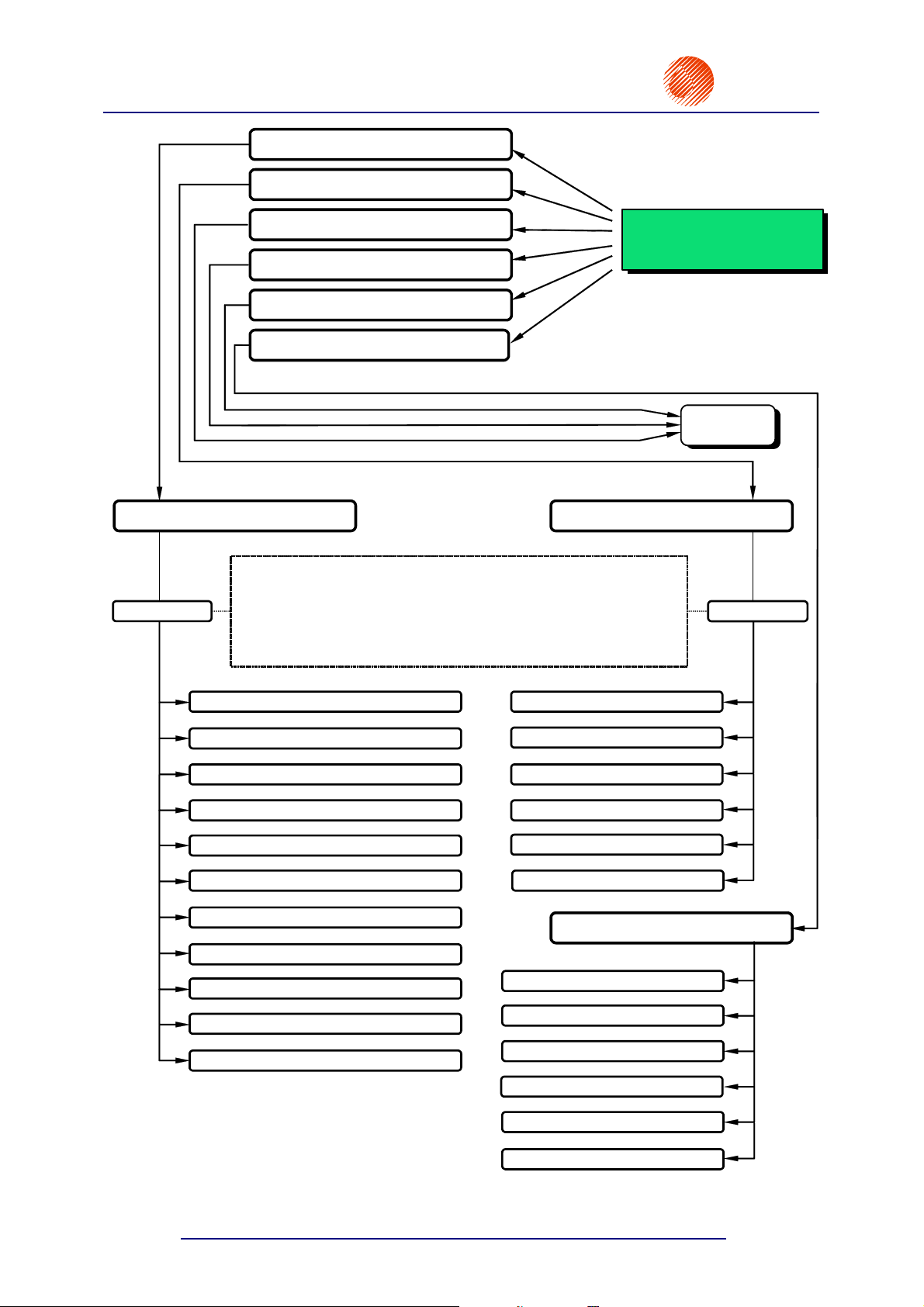
EBS-6100 Printer User's Manual
Paragraph 4 - Operating the Printer
1 TEXT SERVICE
2 PARAMETERS SERVICE
3 PRINTING
4 SERVICE
5 AUX. COMMANDS
6 BOTTLE INFORMATION
EBS
Ink-Jet Systems
MAIN MENU
see next
page
®
TEXT SERVICE
PASSWORD
PARAMETERS SERVICE
The password can be used only if it was defined by the user before.
The user can protect many commands from unauthorised access - see
section 4.4.1.9. Using the Password
The password can be defined, modified and cancelled only in the
TEXT SERVICE menu branch. If all characters of the password are
deleted (with the
1 TEXT EDITION
2 CREATE NEW TEXT
3 COPY & EDIT
4 DELETE TEXT
5 CLEAR LIBRARY
6 READ LIBRARY
7 LINK PARAMETERS
8 CREATE/CHANGE PASS
¦ key), the password-based protection is released.
1 EDIT PARAM. BLOCK
2 CREATE NEW BLOCK
3 COPY & EDIT BLOCK
4 DELETE PARAM. BLOCK
5 CLEAR PARAM.LIBRARY
6 READ LIBRARY
BOTTLE INFORMATION
PASSWORD
26
9 ACTIVATE PASSWORD
A UNIV.DATE REG. CONFIGURATION
Z LIBRARY INFO
1 INK EXPIRE DATE
2 SOLVENT - TIME TO WORK
3 PRINTER/INK/SOLV. TYPE
5 No. OF TXT/1l
8 REMOVE PROTECT TIME
9 IMSVERSION
20070529#20.5
Page 29
r
EBS
Ink-Jet Systems
®
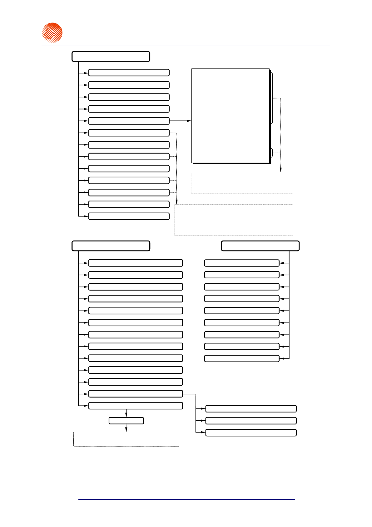
PRINTING
EBS-6100 Printer User's Manual
Paragraph 4 - Operating the Printe
0 EDIT & PRINT CURRENT TEXT
1 STOP PRINTING
2 START PRINT
3 QUICK STOP
4 PRINTING PARAMETERS
5 SAVE CURRENT PARAM.
6 SHIFT COUNTER
7 SET SHIFT COUNTER
8 ROWS SPEED
9 GLOBAL COUNTER
A SET GLOBAL COUNTER
C PRINT SWITCH
D DISPLAY PRINTED TEXT
SERVICE
Vert. direct. : UP
Space : 2,0 mm
Text rpt. : 1
Rpt.dist. : 30,0 mm
Direction : LEFT
Height : LARGE
Offset : 1
Offset2 : 1
Counter delta : 1
Row repetit. : 1
Mode : NORMAL
Speed : SLOW
Interleave : STANDARD
Generator : GEN
Resol. dot/cm : 30
Cnv spd m/min : 10,0
Only some parameters can be modified during
the printing. The settings of others are only
displayed.
If the TEXT SERVICE menu option is protected by a
user password, any modifications to a block of
parameters, change counter and global counter as well
as access to the global counter are allowed only after
the right password has been typed in.
AUX. COMMANDS
1 SERVICE
2 CLEAN NOZZLE
3 V0 OFF
4 V0 ON
5 FAST OFF
6 INK ON
7 INK OFF
8 SOLVENT
9 SET INK STREAM
A STROBOSCOPE
B HV VALUE,PHOTO,SHAFT,AirP state
C SERVICE COMMANDS
D OTHERS
PASSWORD
This is a special service password that protects
an extended set of service commands.
1 OPTIONS
2 DISPLAY ERRORS
3 CLEAR ERRORS
4 READ ERRORS REPORT
5 TIMEAND DATE
6 ACTIVITY TIME
7 LANGUAGE
8 UNLOCK PROTECTION
B SOFTWARE OPTIONS
1 CONVEYER MEASUREMENTS
2 INK FILTER CHANGE
3 PRINTER STORAGE PREPARATION
4.3. Print Head Status
The print head operates in the right way, if the ink jet is properly broken into droplets, the
droplets are properly charged and a flow of unused ink droplets falls into the gutter generating
20070529#20.5
27
Page 30
EBS-6100 Printer User's Manual
Paragraph 4 - Operating the Printer
the correct measurement phasing signal2. Therefore vital parameters are measured within the
print head continuously. The settings of these parameters form the so called print head
status and are shown on the terminal display in the printer status window.
EBS
Ink-Jet Systems
®
A sample head status is given below.
Graphic display
Printer status window
Head status block
The characters of the status block have the following meaning:
The first digit on the first line indicates the quality of phasing - it can vary between 2 and
6 (with 4 being the optimum). Frequent fluctuations of the quantity from the optimum
indicate that the unit is tuned improperly. A question mark
position from time to time means erroneous measurement of phasing. If the mark is
displayed frequently or continuously, this means that the unit is not tuned properly,
especially within the head, and may lead to a phasing error and an alarm.
The second digit on the first line (one character) indicates the head operation mode. The
head can be in one of the following four modes:
? which may appear at this
Fig. 4.3.1.
r (restart) the head operation has been restarted (no phasing, the printing
disabled, the READY lamp on the internal panel is off),
s (stop) the head is ready to start the printing (phase and ink viscosity are
measured, the READY lamp on the internal panel generates steady light),
p (print) the head performs the operation of printing as the result of the
START PRINT or PRINT SWITCH commands (high voltage is turned on, phase
and viscosity are measured, the READY lamp and the HV lamp on the internal
and external panel generate steady light),
v (service) the head is in service mode and enables the user to perform service
operations (phase and ink viscosity are measured, no alarm is indicated if a
phasing error occurs).
The third digit on the first line (one character) indicates the number of the best phase
determined during the phasing process. It can vary between 0 and 7. Variations in
magnitude every now and again at few-second intervals indicate that ink parameters vary
too quickly (and these are allowed only for a short period after the unit has been switched
on). Changes by ±1 are normal for this parameter.
Three positions on the second line are used to show ink viscosity and other information.
The viscosity is given in relation to its rated value of +00. Positive numbers indicate that
viscosity levels are higher than the rated value, with negative numbers the viscosity is
smaller than the rated value. The correct value ranges between +15 and -05. Two other
characters such as > (<) can be displayed at the position in emergency cases: when ink
viscosity rises (drops) above (below) the value of 99.
The following messages may also occur on the second line:
Per phasing error.
2
Phasing - automatic process of controlling the charging of ink droplets. The breaking point at which a continuous ink jet
breaks into droplets varies slightly with time. Therefore the control system needs to update time relations between
the charging and breaking of an ink jet into droplets on an on-going basis.
28
20070529#20.5
Page 31

r
EBS
Ink-Jet Systems
Tge time gap error indicating too high a printing speed that makes it impossible to
Der drop error indicating the failure to apply the optimal breaking voltage.
Aer indicating that no compensation can be made for the KOMPENS option due to
Ter temperature error indicating that the head temperature has fluctuated by
Ovr (overrun) the maximum print rate has been exceeded. This indication may
®
measure phasing and viscosity or too small a distance (see the Rpt.dist. print
parameter) between successive labels as for a given print rate.
too small a value of the Space print parameter or too small a distance (the
Rpt.dist. print parameter) between labels to be printed.
more than 10°C in the print mode. This may result from the improper breaking
of ink into droplets and requires the printing to be stopped for about 60
seconds (high voltage to be turned off with the STOP PRINTING or
QUICK STOP commands) in order to ensure that the droplet break off point is
adjusted automatically to a new temperature. If the working temperature
fluctuates by more than 15°C in relation to the temperature at which the
breaking circuit has been synchronized, adjust the breaking voltage before
starting the operation in such conditions, so that the control equipment
operates in the entire temperature range. The adjustment should be performed
by a service person. In general, the lower the temperature, the higher the
breaking voltage.
appear only when a shaft-encoder is used and it is connected with a sound
signal. The alarm can be cleared with one of the following commands:
START PRINT (even if it is rejected), STOP PRINTING, QUICK STOP and
SERVICE (from the SERVICE submenu).
EBS-6100 Printer User's Manual
Paragraph 4 - Operating the Printe
The third line is not used in EBS-6100 printers.
The fourth line indicates the temperature (°C) inside the head.
The fifth line (ending with “pix”) indicates the type of correction table (7, 16, 25 or 32 pix)
used for printing the current label after the START PRINT command has been selected.
Otherwise, the actual height of the label currently printed is displayed.
NOTE:
• If the START PRINT command has been selected and the
during the printing, the name of a text file printed is displayed (for about 1 second) in
place of the print height. If the
displayed longer.
• If the user is allowed to use the printer for a limited period (under a separate agreement
stating that if the period expires, the printer stops working automatically), the first status
line is displayed in inverted colours (light characters on a dark background, for example
).
4.4. Controlling the Printer
4.4.1. Text Files
F4
function key is pressed
F4
key is pressed several times, the text name is
!
4.4.1.1. General Information on Text Files
All operations related to texts to be printed are available from the TEXT SERVICE
ubmenu.
20070529#20.5
29
Page 32

EBS-6100 Printer User's Manual
Paragraph 4 - Operating the Printer
NOTE:
!
If the TEXT SERVICE submenu is protected by a user-defined password, the user is
prompted to give the password before the submenu is displayed. For details on using a user
password in the printer, see section 4.4.1.9 Using the Password.
Text files are stored in a library in the printer’s memory. Each text file is identified by a name
of up to 8-characters. The name can be built up of alphabetical (small and capital) letters,
digits and some symbols except spaces, dots or characters such as: \ / : * ? ” < > |, e.g.
12345678, AB#%CD&, Weight-5, JUICE-12, DATEtime, Q1, @8, etc. Text names and the
arrangement of text names in the library enable the user to move through even a large set of
text files easily and find the right file without any problems.
Every text file in the library can have the read only attribute assigned to it in order to prevent
it from being deleted or modified by an unauthorised person. The read only attribute can be
assigned to/removed from a single text file or all text files stored in the library. For more
information refer to paragraph 4.4.1.7 Accessing the File Library.
Some commands show the library contents in alphabetical order in the operating window of
the display.
EBS
Ink-Jet Systems
®
The following facilities enable the user to move along the file name directory freely:
• the ¡¢¤£ keys to move the cursor from one name to the other,
• the leading character (a letter or digit) to move the cursor to the first name that starts
with this character,
• the Y¢ (HOME) or Y£ keys to move the cursor to the first name in the
library,
• the Y¡ (END) or Y¤ keys to move the cursor to the last name in the library.
NOTE:
!
If the printer memory is overflowed (with a lot of or very long text files or parameter blocks),
the file names may not be arranged in alphabetical order and some facilities may not be
effective.
The files can be divided into two groups:
simple text files,
complex text files.
The simple text files include the following types of text:
a string of ASCII characters,
a graphical image,
a bar code,
a subfile (another text called by its name).
30
In every case you can create a complex text file from the very beginning or merge text files
(hereinafter called subfiles) that already exist in the library (merging by name). A file created
by merging may be used as part of another file.
20070529#20.5
Page 33

r
®
EBS
Ink-Jet Systems
NOTE:
• Once created, a text file remains in the printer’s memory even if the power supply
has been switched off. A file is removed from the library only when deleted.
• The maximum file length is restricted by the volume of the printer memory available.
• Up to 6 special registers
Registers below).
can be used in a complex text file (see 4.4.1.10 Using Special
EBS-6100 Printer User's Manual
Paragraph 4 - Operating the Printe
WORD PROCESSOR - A Description of Control Keys
¢¡£¤
To navigate within a given subfile or between text files.
!
Y ¢¡
Y £¤
« ¢¡£¤
¥
¦
¨
§
to move the cursor to the first or to the last character in an ASCII
subfile.
To move the entire subfile by one pixel (dot) upwards or
downwards.
To create a new subfile in a given position in relation to the current
subfile.
To switch between two character insertion modes:
INSert/OveRwrite.
To delete a character at the cursor position in a subfile.
To switch between national characters on the keypad. The
selection is indicated in the terminal status window, for example
K:POL.
German characters Polish characters
indication:
character ä corresponds to a characters ąĄ correspond to aA
ö o ćĆ cC
ß s ęĘ eE
ü u łŁ lL
Ä A ńŃ nN
Ö O óÓ oO
ß S śŚ sS
Ü U żŻ xX
źŹ zZ
To edit (modify) parameters of a subfile and to change the subfile
type.
K:GER indication: K:POL
« ¦
« V
U
V
«
Q
To delete the entire subfile.
To edit a graphics subfile.
To cancel the edition (modification) of a current text.
To indicated the end of the edition (save the file in the library).
To switch between two space display modes3. Spaces can be
displayed as (by default) or as blanks. Spaces are always
printed as blanks no matter which display mode is active.
4.4.1.2. Opening and Editing a New Text File
In the main MENU select the TEXT SERVICE item and then the CREATE NEW TEXT
item, type in a subfile name consisting of up to eight characters and confirm.
3
Space – a blank distance between characters; insert it with the ª terminal key.
20070529#20.5
31
Page 34

EBS-6100 Printer User's Manual
Paragraph 4 - Operating the Printer
NOTE:
If the file name exists in the library, the file appears on the terminal display and can be edited.
The word processor starts and various types of simple and complex files can be created. The
word processor opens a simple ASCII file of the maximum height. The file contains one
space. Now you can use the keypad to input a text to be printed. A description of control keys
is given in section 4.4.1.1 General Information on Text Files, paragraph WORD
PROCESSOR - A Description of Control Keys.
EBS
Ink-Jet Systems
®
You can modify text file attributes or type by entering the subfile menu with the
The first item in the subfile menu is Type. All subfile types available together with parameters
and default settings are described later on in this document.
The setting of each of the parameters can be modified with the ¡ and ¢ keys. The setting
of a numerical parameter can also be input directly from the keypad and confirmed with the
V key.
For various types of simple text file (subfile), subfiles are created in different ways. In the
following paragraphs you will find a description of how to create and edit simple files of
various types.
On selecting the subfile type, setting file parameters and typing the file contents, the text file
needs confirming or cancelling.
Subfile Type: Text - ASCII Characters
This type of simple text file (subfile) is a set of alphabetical characters. The standard word
processor offers the Latin alphabet as ASCII characters.
The characters are coded with matrices (or character generators), whose examples are given
below:
MATRIX EXAMPLE
Latin 5x5 pixels
Latin 7x5 pixels
Latin 9x5 pixels
§ key.
Latin 16x10 pixels
Latin 21x15 pixels
Latin 25x15 pixels
Latin 32x18 pixels
Lat__5x5__ pixels
Arab.Dg.7x5 pixels
Cyrillic 7x6 pixels
Cyryl.16x10 pixels
Cyryl.25x19 pixels
32
20070529#20.5
Page 35

r
EBS
Ink-Jet Systems
®
EBS-6100 Printer User's Manual
Paragraph 4 - Operating the Printe
MATRIX EXAMPLE
Terminal keys corresponding to the Spec 7 set of special characters
ABCDE H J M N O PQ T U V W etc.
Spec 7 pixels
Spec 16 pixels
A B C D E F G H J M N O P Q T U V W X Y etc.
Terminal keys corresponding to the
Terminal keys corresponding to the Spec 25 set of special characters
A B C D E F G H I J K L M
Spec 16 set of special characters
Spec 25 pixels
Terminal keys corresponding to the Spec 25 set of special characters
N O P Q R S T U V W X Y Z etc.
Latin 9x7 pixels
Latin 11x8 pixels
Latin 16x14 pixels
When you press the
The parameters have the following meaning:
PARAMETER DESCRIPTION AND SETTINGS DEFAULT
Type :
Char. set :
§ key in the word processor, the parameter menu for a subfile is displayed.
Subfile Type. Any parameters shown below are typical of a Text
subfile.
subText
Character generators see the above specified sample character
matrices. (The number and types of generators installed in the
printer depend on the type of print head used and user
requirements.):
Latin 5x5, Latin 7x5, Latin 9x5, Latin 16x10,
Latin 25x15, Latin 32x18, Latin 21x15, Cyrillic 25x19,
Cyrillic 16x10, Cyrillic 7x6, Arab.Dg.7x5, Lat__5x5__,
Spec 25, Spec 16, Spec 7 Latin 9x7,
Latin 11x8, Latin 16x14.
, Graphic, Barcode, Ins. text
Text
as high as
possible
Typeface :
Distance :
Rotation :
20070529#20.5
Texts can be printed boldface or the printing of every vertical row
can be repeated n times (n=2÷15).
Bold, Normal, Length *2, .... , Length *15
Distance (a number of dots) between characters in vertical rows.
0, 1, 2, .... , 15
Every character within a subfile can be rotated.
None, Right, Upside down, Left
Normal
2
None
33
Page 36

EBS-6100 Printer User's Manual
Paragraph 4 - Operating the Printer
PARAMETER DESCRIPTION AND SETTINGS DEFAULT
The so called special register can also be used as a subfile. Its
contents can vary during printing - see section 4.4.1.10 Using
Special Registers.
Spec.reg. :
Front dis :
Back dist :
NOTE:
!
• While editing a subfile you can modify subfile parameters at any time (by pressing the
• While editing a subfile you can change its type at any time (by pressing the
subfile type has been changed (and possibly subfile parameters modified) and confirmed, the
previous contents of the subfiles are erased.
None, Up counter, Down count., Time, Date,
Spec. chan., Univ.count., Univ. date,
Date+offs., Date+offs.2
Leading spacing before a subfile, given as a number of vertical
rows (dots).
0, 1, 2, 3, .... , 5000
Leading spacing after a subfile, given as a number of vertical rows
(dots).
0, 1, 2, 3, .... , 5000
EBS
Ink-Jet Systems
None
0
0
§ key).
§ key). After the
®
Subfile Type: Graphics
A GRAPHICS subfile is a block of pixels (on the display) or dots (on an overprint) that are
set/erased separately.
When the
subfile. The parameters have the following meaning.
PARAMETER DESCRIPTION AND SETTINGS DEFAULT
Type :
Height :
Length :
Front dis :
§ key is pressed in the word processor, parameter menu is displayed for your
Subfile type. Any parameters shown below are typical of a Graphics
subfile.
Graphic
The maximum height (number of pixels) of a graphics block equals
the maximum height, Hmax, of a printable vertical row.
1, 2, 3, .... , Hmax
Expected length (number of pixels) of a graphics block.
1, 2, 3, .... , 32767
Blank space (number of vertical rows) before a graphics block.
0, 1, 2, 3, .... , 5000
, Barcode, Ins. text, subText
Text
Hmax
the same
as the
height
setting
0
Back dist :
34
Blank space (number of vertical rows) after a graphics block.
0, 1, 2, 3, .... , 5000
0
20070529#20.5
Page 37

®
r
EBS
Ink-Jet Systems
NOTE:
• While editing a graphics block you can modify parameters of a Graphic subfile at any time (by
pressing the
• After the edition of a graphics block has been completed, empty vertical rows to the right of the
last non-blank row are deleted automatically. Therefore the block length changes and differs
from the original setting.
By pressing the «V keys you will move to the graphics processor, where every
dot can be inserted/erased. The image is magnified four times to make individual pixels more
visible on the display. The graphic cursor coordinates are shown in the status window on the
terminal display. A reference point for them is at the top left corner
§ key).
X: horizontal coordinate Y: vertical coordinate.
EBS-6100 Printer User's Manual
Paragraph 4 - Operating the Printe
of the graphic block.
GRAPHICS PROCESSOR - A Description of Function Keys
ª
To show in inversion (off/on) a point indicated by the cursor.
To switch between the editor pen modes: UP / SET / CLEAR.
UP lift up the pen,
¨
SET set the pen in the >write< mode,
CLEAR set the pen in the >erase< mode.
The pen status is displayed in the terminal status window.
!
I
¢¡£¤
Y
¢¡£¤
¥
¦
Y ¥
Y ¦
V
U
To invert (enable/disable) every element of a graphic subfile irrespective of
the pen state defined with the
To move the cursor right, left, up or down according to the pen mode. If the
cursor is moved right, beyond the length limit, new vertical rows are inserted
and the subfile length is modified.
To move the cursor by 8 dots in the direction indicated by the arrow.
To insert an empty vertical row and move the following rows by one row to
the right.
To delete the vertical row where the cursor is and move the rows further on
by one dot to the left.
To insert one blank horizontal row and move the below rows by one dot
down (with no change in the subfile height).
To delete the horizontal row where the cursor is and move the downward
rows by one dot up (with no change in the subfile height).
To confirm modifications and return to the word processor.
To cancel modifications and return to the word processor.
Subfile Type: BAR CODE
A BAR CODE subfile is a bar-code block. The processor offers an option to create various
barcodes defined by the applicable standards.
¨ key.
20070529#20.5
35
Page 38

EBS-6100 Printer User's Manual
Paragraph 4 - Operating the Printer
EBS
Ink-Jet Systems
When the § key is pressed in the word processor, parameter menu is displayed for your
subfile. The parameters have the following meaning:
PARAMETER DESCRIPTION AND SETTINGS DEFAULT
Subfile type. Any parameters shown below are typical of a Bar
Code subfile.
Type :
Barcode
, Ins. text, subText, Graphic
Text
Bar-code type:
Code :
Datalogic, Matrix, 2/5 5 Bars, Interleaved,
Datalogic
Code 39, EAN-8, EAN-13,
UPC-A, UPC-A EBS, Code 128,
EAN-128, Code 128B, ITF8, ITF14
Information stored in the bar code. It shall follow bar-code
specific rules.
Contents :
e.g. 590069701766 or the EAN-13 bar code
For the EAN-8 code input 7 characters (the 8
th
one is calculated
automatically). For EAN-13 input 12 characters (the 13
th
one is
No setting
calculated automatically).
®
The maximum bar height (a number of pixels) equals the
maximum height, Hmax, of a printable vertical row.
1, 2, 3, .... , Hmax
Height :
10, 11, 12, .... , Hmax for EAN-8 and EAN-13
Defines how many times the printing of a vertical row is
repeated. It is used to scale the width of a bar code block.
Elongat.X :
1, 2, 3, .... , 16
A bar code can be the so called special register - see section
4.4.1.10 Using Special Registers paragraph Object Counters.
None, Up counter, Down count.
Spec.reg. :
A blank space (a number of vertical rows-dots) before a code
block.
Front dis :
0, 1, 2, 3, .... , 5000
A blank space (a number of vertical rows-dots) after a bar code
block.
Back dist :
0, 1, 2, 3, .... , 5000
An indication, whether a 5 or 7 pixel-high numerical caption is to
be added beneath the bar code.
Signature :
5 pix, 7 pix, NO
The numerical caption is added only when the bar-code height
exceeds 12 pixels.
Hmax
1
None
0
0
5 pix
Sign.dist :
36
A 1 or 2-pixel distance can be applied between a bar code and
a caption beneath.
1 pix, 2 pix
1 pix
20070529#20.5
Page 39

®
r
EBS
Ink-Jet Systems
PARAMETER DESCRIPTION AND SETTINGS DEFAULT
Inversion :
An indication, whether a bar code is to be printed in inverted
colours.
YES, NO
When a bar code is printed in inversion, no bars are printed but
only spaces are printed instead, and filled-in fields are added
before and after the bar code. The inversion is used to print bar
codes with white ink on a black background.
EBS-6100 Printer User's Manual
Paragraph 4 - Operating the Printe
NO
The EAN-13 car code not in
inversion, i.e.
Inversion=NO (32 pixels).
NOTE:
• Subfile parameters can be changed at any time during the edition of a Barcode subfile (by
pressing the
• In some cases the ranges of parameters may be reduced to ensure the bar-code standards
are met and editing rules are followed.
§ key).
The EAN-13 bar code in
inversion, i.e. Inversion=YES
(32 pixels).
Subfile Type: TEXT NAME
Every file stored with a name in the library can be merged into another file as ‘a subfile
called by its name’. The
inside the file it has been merged into. It can only be edited as a separate library file.
When the
your subfile. The parameters have the following meaning:
PARAMETER DESCRIPTION AND SETTINGS DEFAULT
Type :
§ key is pressed in the word processor, the parameter menu is displayed for
Subfile type. Any parameters shown below are typical of
a Ins. text subfile.
Ins. text
TEXT NAME subfile is a simple or complex subfile. It cannot be edited
, subText, Graphic, Barcode
Text
!
Specify a name of a library-stored file. The file name can also be
Text name :
Front dis :
Back dist :
NOTE:
Subfile parameters can be modified during the edition of an Ins. text subfile at any time (by
pressing the
selected from the library by pressing the ¨ key.
A blank space (a number of vertical rows) before a subfile that is
called by its name.
0, 1, 2, 3, .... , 5000
A blank space (a number of vertical rows) after a subfile that is
called by its name.
0, 1, 2, 3, .... , 5000
§ key).
No setting
0
0
4.4.1.3. Editing an Existing Subfile
In the main MENU select the TEXT SERVICE item and then the TEXT EDITION item.
20070529#20.5
37
!
Page 40

EBS-6100 Printer User's Manual
Paragraph 4 - Operating the Printer
After a text file has been selected from the library, a word processor starts running and you
can edit the text file or its parameters.
A description of control keys used by the processors is given in section 4.4.1.1 General
Information on Text Files, paragraph WORD PROCESSOR - A Description of Control
Keys. For a description of how to edit individual subfile types see section 4.4.1.2 Opening
and Editing a New Text File.
After the edition has been completed, confirm or cancel all modifications.
4.4.1.4. Copying and Editing a Text File
You can create a new text file by copying an existing file from the library and saving it with
another name. In the main MENU select the TEXT SERVICE item and then the
COPY & EDIT BLOCK item.
The display shows the text file library from which you should select the name of a text file to
be copied (see also section 4.4.1.1 General Information on Text Files).
Then input an up to 8-character name for the new file that has just been copied.
If the new name exists in the library, the following message is displayed: *TEXT EXISTS*.
After the file name has been typed in, the word processor starts. The file is displayed on the
terminal. It can be edited as described in section 4.4.1.3 Editing an Existing Subfile.
EBS
Ink-Jet Systems
®
4.4.1.5. Deleting a Text File
In the main MENU select the TEXT SERVICE item and then the DELETE TEXT item.
The display shows the text file library from which you should select the name of a text file to
be deleted and confirm the selection (see also section 4.4.1.1 General Information on Text
Files).
!
NOTE: Once deleted the file cannot be restored.
4.4.1.6. Deleting the File Library
Deleting the library means deleting all text files that are stored in the printer’s memory. In the
main MENU select the TEXT SERVICE item and then the CLEAR LIBRARY item.
When confirmed, the text files are deleted irretrievably
.
4.4.1.7. Accessing the File Library
Reviewing the file library means reviewing all text files that are stored in the printer’s
memory, together with parameter blocks assigned to them. In the main MENU select the
TEXT SERVICE item and then the READ LIBRARY item.
38
File names linked with appropriate parameter-block names are displayed in the operating
window in alphabetical order and separated with “:”. The window can be used not only to view
text files but also to separate the parameter block from a text file selected and to
assign/remove the read only attribute in order to prevent the text files from being deleted or
modified by unauthorised persons. The text files with the read only attribute are marked with
a “+” sign that precedes the file names. The text file attribute markers (“+” or “space”) are also
20070529#20.5
Page 41

r
®
EBS
Ink-Jet Systems
displayed with the TEXT EDITION and COPY & EDIT commands but they cannot be modified
with these commands.
The following functions are available while the text files library is viewed:
EBS-6100 Printer User's Manual
Paragraph 4 - Operating the Printe
Terminal key
Function
¤£
An alphabetical or
numerical key
Y¢ (HOME)
Y£
lub
Y¡ (END) lub
Y¤
ª
¥
¦
To display the next/previous screen showing text file names.
To display the text file names starting from the first name that begins with
a given character.
To place the cursor on the first name in the library.
To place the cursor on the last name in the library.
To assign/remove the read only attribute to/from a selected text file. The
operation is available only when the service password is enabled. If the
password level is too low, you will be asked for a password when you
make an attempt to change the attribute.
To assign the read only attribute to every text in the library. The option is
available only when the service password is enabled. If the password
level is too low, you will be asked for a password when you make an
attempt to change the attribute.
To remove the read only attribute from every text in the library. The
option is available only when the service password is enabled. If the
password level is too low, you will be asked for a password when you
make an attempt to change the attribute.
¨
NOTE: If no text files are defined in the library, the command is ignored.
To detach the parameter block from the text file previously selected with
the cursor.
4.4.1.8. Linking File Names with Parameter-Block Names
Certain print parameters need to be set during printing (see section 4.4.3.5 Print
Parameters). When you change the text to be printed (e.g. as the line of products to be
labelled changes), the parameters need to be adjusted accordingly. Therefore it would be
advisable to have a tool that might enable you to do the following:
Store print parameters for a given text file,
Link the parameters stored with the text file to be printed,
Set all parameters for the text file automatically just before the printing, after the print
command has been selected.
A solution to meet the above requirements is offered by EBS printers. Every text file (that is
stored in the library) can be linked with a parameter block and such a pair can be stored in the
file library. To do this, follow the procedure below:
In the main MENU select the TEXT SERVICE item and then the LINK PARAMETERS item.
The display shows the text file library from which you should select a text file name (see also
section 4.4.1.1 General Information on Text Files). Then the parameter block library is
displayed, from which you should select a parameter block name.
!
20070529#20.5
39
Page 42

EBS-6100 Printer User's Manual
Paragraph 4 - Operating the Printer
Now the text file name is paired off with the parameter-block name and the relevant
information remains in the printer’s memory even if the power supply is switched off.
For how to detach the parameter block from the a selected text file see paragraph
4.4.1.7 Accessing the File Library.
4.4.1.9. Using the Password
The user can secure access to the following commands that are called protected
commands further on:
all commands in the TEXT SERVICE submenu,
all commands in the PARAMETERS SERVICE submenu,
commands in the PRINTING submenu, such as:
• SAVE CURRENT PARAM.,
• SET SHIFT COUNTER,
• GLOBAL COUNTER,
• SET GLOBAL COUNTER.
The objective is to protect text files, parameter blocks and the object counter against
accidental or deliberate access by unauthorised persons.
This security feature is implemented by defining a password and enabling the password. Any
access to the secured MENU commands is possible only after the password has been typed
in. When the right password has been typed in, the commands previously unavailable
become available until the password function is enabled again or the printer is turned off.
When the password is defined, the password function is enabled automatically after the unit
has been switched on.
EBS
Ink-Jet Systems
®
Defining a User Password
In the main MENU select the TEXT SERVICE item and then the CREATE/CHANGE PASS
item.
The request to type in a user password is displayed. Enter from 1 up to 8 characters and
confirm, and then type in the password again in order to certify. The characters input are not
displayed explicitly. Only asterisks (******) are shown on the display.
If the password has already been defined, the CREATE/CHANGE PASS option is followed by
as many asterisks as the number of characters within the password.
Enabling the User Password
The password function is enabled to secure protected commands against any
unauthorised use. The commands are available until the password function is enabled (turned
on). The password needs to be defined first. After the password function has been enabled
any access to the submenus and commands specified above is preceded by a request to type
in the password.
In the main MENU select the TEXT SERVICE item and then the ACTIVATE PASSWORD
item. The password function is on from that moment on.
,
40
Changing the User Password
The user password can be changed at any time. In the main MENU select the
TEXT SERVICE item and then the CREATE/CHANGE PASS item.
20070529#20.5
Page 43

r
®
EBS
Ink-Jet Systems
The request to type in a user password is displayed. Enter from 1 up to 8 characters and
confirm, and then type in the password again in order to certify. The characters input are not
displayed explicitly. Only asterisks (******) are shown on the display.
NOTE: Note that the old password can only be modified (cancelled) when it has been
defined to protect the TEXT SERVICE submenu. Therefore no unauthorised
person can modify (cancel) the password.
EBS-6100 Printer User's Manual
Paragraph 4 - Operating the Printe
Deleting the User Password
The user password used to secure the protected commands can be deleted.
In the main MENU select the TEXT SERVICE item and then the
CREATE/CHANGE PASS item.
!
The user password is displayed but not explicitly (only asterisks are seen on the display).
Delete all characters with the
PASSWORD DELETED message and all security features are then removed.
NOTE: If the password has been forgotten, you can contact the Manufacturer
(distributor) to cancel the password without entering the TEXT SERVICE
submenu - see section 4.4.5.8 Releasing Protections.
¦ key. The system will confirm the action with the
4.4.1.10. Using Special Registers
Special registers are a specific type of ASCII subfile that are updated after each overprint
has been made. The register settings can be changed with events such as changing date,
changing time, detecting an object by a photo detector, receiving a signal from an external
device such as scales.
The Spec.reg. parameter indicates whether
a given subfile is to be a text file or a
special register. You can find it in the
parameter menu of the word processor by
pressing the
§ key.
!
Type : Text
Char. set : Latin 25x15
Typeface : Normal
Distance : 2
Rotation : None
Spec.reg. : None
The Spec.reg. parameter defines the following special registers:
None, Up counter, Down count., Time, Date,
Univ.count., Univ. date, Date+offs., Date+offs.2,
NOTE: Up to 6 special registers
Each of them is described in the following section.
20070529#20.5
can be used in one complex text file.
Spec. chan.
!
41
Page 44

EBS-6100 Printer User's Manual
Paragraph 4 - Operating the Printer
Object Counters
The following counters are used to print a consecutive number on every object
automatically:
• an incremental counter,
• a decremental counter.
The counters are timed by a photo detector. An increment (varying from 1 to 9, in ascending
or descending order) for both counters is set with the Counter delta parameter, which is
available in the PRINTING PARAMETERS command within the submenu PRINTING.
While editing a subfile that is to be used as an object counter, insert into the subfile a number
that consists of so many digits so that the entire user-requested range is covered. The
number is the initial setting of the counter at the same time. The number can be preceded and
followed by any characters.
EXAMPLE:
If number 056 has been put into the subfile, then:
• for the incremental counter – after 999 has been reached, the counter is cleared
• for the decremental counter – after 000 has been reached, the counter is set to
EBS
Ink-Jet Systems
and the counting goes up from zero (056, 057,
058, ... , 999, 000, 001, 002, etc.),
999 and the counting goes down to zero (056, 055,
054, ... , 000, 999, 998, 997, etc.).
®
NOTE:
!
• The object counter register is also used to print bar codes. Then the bar codes are
printed instead of consecutive numbers and the code corresponds to the consecutive
number that is counted by the special register. See section 4.4.1.2 Opening and
Editing a New Text File, paragraph Subfile Type: B
• The incremental counter special register can also count in the hexadecimal format. On
selecting the Spec.reg.=Up counter parameter from the subfile parameter menu, press
§ key and then change the setting of the Counter type parameter from DEC (the
the
default setting standing for counting in decimal form) to HEX.
AR CODE.
Date and Time
The Time register is used to print current time in the 24-hour system on objects
automatically.
The Date register is used to print current date in the leap year system on objects
automatically.
The structure of date and time registers is similar. If you edit a subfile that is to be a time
(date) register, follow the rules below:
• the time (date) register is built of up to 8 meaningful characters (6 digits to be updated
and 2 separators),
• when the register is updated, data is input starting from a non-space character until
8 defining characters are inserted or until another space or the end-of-subfile are
encountered,
• every third character is treated as a separator; the separator can be any character,
• hours (day), minutes (month), seconds (year) are two-digit numbers and the separator is
any non-space
• the register can contain less than 8 characters; then the characters are cut off on the
right.
4
character,
EXAMPLE:
Time is coded in the following way:
Hours Separator Minutes Separator Seconds e.g. 00:00:00 or 13/44/56.
Hours Separator Minutes e.g. 00:00 or 13/44, if seconds are not to be printed.
4
Space – a blank distance between characters; it is inserted with the ª key on the terminal.
42
20070529#20.5
Page 45

r
®
EBS
Ink-Jet Systems
Hours e.g. 00 or 13, if minutes or seconds are not to be printed.
Date is coded in the following way:
Day Separator Month Separator Year e.g. 00.00.00 or 17/05/02.
Day Separator Month e.g. 00.00 or 17/05, if year is not to be printed.
Day e.g. 00 or 17, if month and year are not to be printed.
For more date and time options see the universal date register below.
EBS-6100 Printer User's Manual
Paragraph 4 - Operating the Printe
Universal Counter
The universal counter is a special counter to count objects that move in front of the print
head. The counter is timed by a standard photo detector. The universal counter consists of
two elements:
• a main counter,
• an auxiliary counter.
The main counter is always printed, while the auxiliary counter either can or cannot be
printed.
The main counter setting changes only when the auxiliary counter has been
overflowed.
Therefore, when you edit a subfile that is to be a universal counter of objects, the subfile
should contain the following:
For the main counter and printable auxiliary counter - two numbers (groups of digits) with
as many digits as may be needed to cover the user-defined range. The groups must be
separated with a separator that is different from digits or space
designed for the main counter, the second for the auxiliary counter.
For the main counter and unprintable auxiliary counter – a number (a group of digits) with
as many digits as may be needed to cover the user-defined range. The group is designed
for the main counter, whereas the setting of the auxiliary (unprintable) counter is defined
by the Cnt.value2 parameter – see below.
The operation of two counters is determined by universal counter parameters. To access the
parameters start the word processor and follow the procedure below:
• Position the cursor on the subfile that is a special register and press the
the terminal,
• Set Spec.reg.=Univ.count.,
• Press the
are displayed:
§ key on the terminal again. The following universal counter parameters
. The first group is
§ key on
20070529#20.5
43
Page 46

EBS-6100 Printer User's Manual
Paragraph 4 - Operating the Printer
Description Settings
CONTINUE,
®
EBS
Ink-Jet Systems
Print beg. - see below,
Mode - see below,
Beg.value1 - initial setting 5*),
Min.value1 - minimum setting,
Max.value1 - maximum setting,
Cnt.delta1 - increment,
Beg.value2 - initial setting *),
Min.value2 - minimum setting,
Max.value2 - maximum setting,
Cnt.delta2 - increment,
Cnt.value2 - current setting of the counter; it is
vital for the auxiliary unprintable
counter,
0 suppress - Indication whether to hide leading
zeros.
If the setting is YES the leading zeros are
replaced with spaces in both elements, and
both elements are moved to the separator.
Spc.Md.max - the number of photo detector
activations for which unchanged settings of the
main counter and auxiliary counter (a
subcounter of the auxiliary counter for the
same prints) are to be printed,
Spc.Md.cnt - the setting of the Spc.Md.max
parameter from which the printing is to be
resumed,
BEG.VALUE,
MIN/MAX
Standard,
Special
0 ÷ 4 294 967 295
0 ÷ 4 294 967 295
0 ÷ 4 294 967 295
0 ÷ 255
0 ÷ 65 535
0 ÷ 65 535
0 ÷ 65 535
0 ÷ 255
0 ÷ 65 535
YES, NO
0 ÷ 65 535
0 ÷ 65 535
applies to the first element
of the universal counter
(the main counter)
applies to the second
element of the universal
counter
(the auxiliary counter)
available only for the
following universal counter
setting Mode=Special
Pal.countr - the number of packages on a pallet
0 ÷ 65 535
– it defines “jumps” of the main counter for
successive pallets, so that consecutive
numbering is used during the placing of
packages on pallets.
5
*) Both elements of the universal can be set to their initial settings in the Standard mode only. In the Special mode the
settings need to be modified by editing the subfile of the universal counter directly.
44
20070529#20.5
Page 47

r
®
EBS
Ink-Jet Systems
Two modes of operation set with the Mode parameter are available for the universal counter:
standard and special.
1). The universal counter with Mode=Standard.
The first setting of the universal counter printed after the printing has been resumed
(i.e. after the START PRINT command) depends on the Print beg. parameter. The
settings of the parameter have the following meaning:
• CONTINUE - a consecutive setting of the universal counter (defined by the
settings of other counter parameters) is printed as if the printing has not been
stopped. This means that the sequence of two commands: STOP PRINTING and
START PRINT does not break the order of numbering, no matter how many
times it is repeated,
• BEG.VALUE - both elements of the counter are set to figures defined by the
Beg.value1 and Beg.value2 parameters, respectively. The counters count
between the minimum and maximum settings. With such settings, the printing can
be resumed from any state. The feature can be used to label some missing
objects,
• MIN/MAX - both elements of the counter are set with settings defined by the
Min.value1 and Min.value2 counter parameters.
EBS-6100 Printer User's Manual
Paragraph 4 - Operating the Printe
NOTE:
• The setting of the (main, auxiliary) counter is incremented, when its minimum
setting is smaller that its maximum setting. Otherwise it is decremented,
• The (main, auxiliary) counter overflows, when its maximum setting is replaced with
the minimum setting,
• Each time you change the type of special register to universal counter, all counter
parameters are set to the following initial settings:
Print beg.=CONTINUE, Mode=Standard
Beg.value1=1, Min.value1=1,
Max.value1=4 294 967 295, Cnt.delta1=1,
Beg.value2=1, Min.value2=1,
Max.value2=1, Cnt.delta2=1,
Cnt.value2=1, 0 suppress=NO.
• The overflow of the main or auxiliary counters can additionally be indicated by a
change at the output of one of the printer’s external ports. The change can
optionally be used to control external devices (option).
In this mode the Spc.Md.max, Spc.Md.cnt and Pal.countr parameters are not available
and cannot be set.
EXAMPLE 1:
Creating a standard pallet counter
Assumptions: Packages moving on a factory conveyor are stored on a pallet in a single
layer. There are 4*5=20 packages in the layer. Packages are placed on the pallet in A
and B order and directions, as shown in the illustration below. The pallets are put one
onto the other in 4 layers (C) on all shelving in the store. The packages need to be
labelled in such a way that the pallet number and consecutive package number on each
pallet are printed. When the printing is interrupted and then resumed, the consecutive
number should be printed. After 4 pallets (80 packages) have been labelled, the counter
should be reset (i.e. set to its minimum setting) and the counting resumed.
!
20070529#20.5
45
Page 48

EBS-6100 Printer User's Manual
Paragraph 4 - Operating the Printer
Create a subfile in the form of a special register (a universal counter) within the text file
to be printed onto packages. Type in the following text:
universal counter parameters:
Print beg.=CONTINUE, Mode=Standard, Beg.value1=1,
Min.value1=1, Max.value1=4, Cnt.delta1=1,
Beg.value2=1, Min.value2=1, Max.value2=20,
Cnt.delta2=1, Cnt.value2=1, 0 suppress=NO
The following labels are printed on packages if the above settings have been set:
001/001, 001/002, ... , 001/020, 002/001, 002/002, ... , 002/020, 003/001, ...... , 004/019,
004/020, 001/001, etc.
NOTE: If the numbering of packages has been interrupted for some reason during the
printing, you can stop the printing, reset the Print beg. parameter to
BEG.VALUE, set both counters to the initial settings with the Beg.value1 and
Beg.value2 parameters and resume the printing.
EBS
Ink-Jet Systems
000/000. Set the following
®
Direction in
which pallets
are placed
C
A
000/ 000
001/ 001
000/ 000
000/ 000
004/ 001
000/ 000
000/ 000
003/ 001
000/ 000
000/ 000
002/ 001
000/ 000
000/ 000
001/ 001
000/ 000
000/ 000
001/ 005
000/ 000
000/ 000
004/ 005
000/ 000
003/ 005
000/ 000
002/ 005
001/ 005
000/ 000
000/ 000
000/ 000
000/ 000
000/ 000
000/ 000
000/ 000
000/ 000
000/ 000
000/ 000
000/ 000
000/ 000
000/ 000
000/ 000
000/ 000
000/ 000
001/ 009
000/ 000
004/ 009
000/ 000
003/ 009
000/ 000
002/ 009
000/ 000
001/ 009
000/ 000
000/ 000
001/ 013
000/ 000
000/ 000
000/ 000
004/ 013
000/ 000
000/ 000
003/ 013
000/ 000
000/ 000
002/ 013
000/ 000
001/ 013
000/ 000
000/ 000
000/ 000
000/ 000
000/ 000
000/ 000
000/ 000
000/ 000
000/ 000
000/ 000
000/ 000
000/ 000
000/ 000
000/ 000
000/ 000
000/ 018
001/ 017
000/ 018
004/ 017
000/ 018
003/ 017
000/ 018
002/ 017
000/ 018
001/ 017
000/ 020
000/ 019
000/ 020
000/ 019
000/ 020
000/ 019
000/ 020
000/ 019
000/ 020
000/ 019
1
1 2 3 4 5
B
Order A, B and direction in which
packages are stored on pallets
Fig. 4.4.1.10.1. The operation of the universal counter in Example 1
2). Universal counter with Mode=Special.
Additional parameters of the universal counter are available in this mode. They are:
Spc.Md.max, Spc.Md.cnt and Pal.countr - see the table above. With them, the
numbering of products can be automated and fit subsequent packing and storing on
pallets or shelves in a hierarchical way. In this mode the other parameters are similar
to those used in the Standard mode except for the Beg.value1 and Beg.value2
parameters. These two parameters are not available and therefore cannot be used to
set both counters of the universal counter to their initial settings. In the Special mode,
the initial settings need to be introduced by editing the universal-counter subfile
directly (and inputting 2 groups of digits and a separator).
1st pallet
4th pallet
3rd pallet
2nd pallet
1st pallet
4
3
2
2nd shelving
1st shelving
46
EXAMPLE 2:
Creating a special counter to allow for peculiarity of product packing in a company
Assumptions: Small unit packages (products) moving sequentially on a factory conveyor
are packed in fours into type I packages, then the type I packages are put in groups of 64
into boxes (type II packages). The type II packages are stored on pallets in one layer, with
4*5=20 packages in the layer. The packages are arranged on the pallet in A, B order and
20070529#20.5
Page 49

r
EBS
Ink-Jet Systems
®
EBS-6100 Printer User's Manual
Paragraph 4 - Operating the Printe
in the direction as shown in the illustration below. The pallets are put one onto the other in
3 layers (C) on all shelving in the store. The unit packages need to be labelled in such a
way that the type I and type II packages are clearly identified to find the product.
Therefore the type II package number (the main counter) and type I package number (the
auxiliary counter) are printed on each unit package. All products in the type I package
have the same label (a subcounter of the auxiliary counter). When the printing is
interrupted and then resumed, the consecutive number is printed. After products on 3
pallets (4*64*60=15360 packages) have been labelled, the counters need to be reset (i.e.
set to their initial settings) and the counting resumed – see the illustration.
17
18
13
14
09
10
05
06
01
02
1st pallet
2nd shelving
Print head
19
20
60
Direction
in which
pallets are
placed
40
C
20
A
1 2 3 4 5
A, B order and the direction of placing
type II packages on pallets
04/63
04/64
04/64
4 unit packages labelled with
the same numbers
print parametr Spc.Md.max=4
16
59
56
39
36
19
16
B
04/64
04/64
58
38
18
15
12
57
54
55
52
37
34
35
32
17
14
15
12
type I
04/64
04/64
11
53
51
33
31
13
11
04/46
04/64
07
08
48
28
08
04
49
50
30
10
46
47
44
29
26
27
24
09
06
07
04
04/13 04/05 04/09 04/01
04/14 04/06 04/10 04/02
04/04 04/04 04/04 04/07
04/15 04/07 04/11 04/03
04/04 04/04 04/04 04/08
04/16 04/08 04/12 04/04
04/04 04/04 04/04 04/03
04/04 04/04 04/04 04/09
04/04 04/04 04/04 04/04
04/32 04/24 04/28 04/20
04/04 04/04 04/04 04/09
04/04 04/04 04/04 04/05
04/04 04/04 04/04 04/00
04/48 04/40 04/44 04/36
04/04 04/04 04/04 04/01
04/64 04/56 04/60 04/52
Value of the auxiliary counter
(not printed on these packages)
03
45
42
43
25
22
23
05
02
03
type II
41
21
01
2
1
3rd pallet
1st shelving
2nd pallet
1st pallet
4
3
Value of the main
counter (not printed
on these packages)
64 type I packages
packed into a type II
package. Type II
packages are placed on
pallets
20070529#20.5
Fig. 4.4.1.10.2. The operation of the universal counter in Example 2
A subfile needs to be embedded into the text file to be printed on packages. It needs
to be a universal counter special register. Its contents of
20/64 should be typed in
via the keypad. The counter parameters should be set as follows:
Print beg.=CONTINUE, Mode=Special, Min.value1=1,
Max.value1=60, Cnt.delta1=1, Min.value2=64,
Max.value2=1, Cnt.delta2=1, Cnt.value2=1,
0 suppress=NO, Spc.Md.max=4, Spc.Md.cnt=1,
Pal.countr=20
47
Page 50

EBS-6100 Printer User's Manual
Paragraph 4 - Operating the Printer
When the above settings are made, the following labels are printed on each of the
packages moving on a factory conveyor in front of the print head:
20/64, 20/64, 20/64, 20/64, 20/63, ... , 20/02, 20/01, 20/01, 20/01, 20/01, 19/64, ... ,
01/02, 01/01, 01/01, 01/01, 01/01, 40/64, 40/64, 40/64, 40/64, 40/63, ... , 21/02,
21/01, 21/01, 21/01, 21/01, 60/64, 60/64, 60/64, 60/64, 60/63, ... , 41/02, 41/01,
41/01, 41/01, 41/01, 20/64, etc.
and the counting is resumed
NOTE: If the numbering of packages has been interrupted for some reason during
the printing, you can stop the printing, edit groups of digits within the
counter subtext, set a setting to continue the counting at the same point in
process with the Spc.Md.cnt parameter and resume the printing.
Universal Date and Time
You can use a special register (Univ. date) in order to print current date and time (in
various formats) on objects automatically.
Below, there is a list of characters that can be used to encode date and time. Elements of
the universal date register can be preceded, separated and followed by any characters
different from the specified below.
D tens of day in the current date,
A units of day in the current date,
M tens of month in the current date,
O units of month in the current date,
Y tens of year in the current date,
E units of year in the current date,
EBS
Ink-Jet Systems
®
B tens of hours of the current time,
C units of hours of the current time,
I tens of minutes of the current time,
J units of minutes of the current time,
T tens of seconds of the current time (option),
U units of seconds of the current time (option),
NOTE: During printing, the above mentioned date and time components (D, A, M, O, Y,
E, B, C, I, J, T, U) are replaced with digits (0-9), as standard. It is also possible
that an additional way of coding is used and the above mentioned date and time
components are replaced with any characters available from the terminal keypad
rather than with digits. The assignment is made in the submenu TEXT SERVICE
UNIV.DATE REG. CONFIGURATION DIGIT CODING. The same
characters can be assigned to different digits. For example, the date of
24/10/2004, coded as DA/MO/20YE, can appear on a print as x$/HZ/20Z$, if the
following assignments have been made: 0 => Z, 1 => H, 2 => x, 4 => $.
W tens of week-of-the-year number,
K tens of week-of-the-year number,
a number of week of the year coded with one character. The assignment is made in the
submenus TEXT SERVICE UNIV.DATE REG. CONFIGURATION
WEEK CODING (1 CHAR),
y tens of year of the current date by week-of-the-year number (e.g. if week 53 ends on
th
5
January next year, then 5th January falls within the previous year’s week),
e units of year of the current date by week-of-the-year number,
m number of month printed with the following encoded letters: A B C D E F G H L M N
P (corresponding to numbers from 1 to 12, respectively). The assignment can be
changed in the submenus TEXT SERVICE UNIV.DATE REG. CONFIGURATION
MONTH CODING (1 CHAR),
P hundreds of day-of-the-year number,
Q tens of day-of-the-year number,
S units of day-of-the-year number,
N number of day of the week (1- Monday, 2-Tuesday, ... , 7-Sunday),
F the first letter of the month,
48
20070529#20.5
Page 51

r
®
EBS
Ink-Jet Systems
G the second letter of the month,
H the third letter of the month,
b the number (between 0 and 23) of the hour of day of current time coded with a single
Z working shift identifier,
A shift identifier can be set for each of up to 8 working shifts (within a 24-hour day), so
can shift start and finish times for each shift separately on working days (from Monday to
Friday) and on the other days (Saturday and Sunday).
In order to change the settings select the item SHIFT DEFINITION from the submenu
TEXT SERVICE UNIV.DATE REG. CONFIGURATION. A list of additional parameters
of the special register Universal date and time is displayed for the coding element Z of
this register, that is for the shift identifier. This is where the following parameters can be
modified.
• Any alphanumerical character available on the terminal keypad can be used as
• The shift start time needs to be specified as the sequence of hh:mm (hours:minutes).
• If a character X is specified instead of a shift start time, it means that a given and
character.
The assignment of any character available via the terminal keypad to each hour of
day is made in the submenu TEXT SERVICE
UNIV.DATE REG. CONFIGURATION HOUR CODING (1 CHAR). The same
characters can be assigned to different hours.
Working shifts identified by numbers 1, 2 or 3 cover the following time periods as
standard:
st
1
shift - from 6:00 to 14:00, 2nd shift - from 14:00 to 22:00,
rd
3
shift - from 22:00 to 6:00, on every day of the week.
identifier.
The shift times need to be specified in such a way that the following condition is met:
the next shift needs to start later than the previous one.
subsequent shifts do not exist, and the identifier is printed in accordance with the
previous shits’ parameter settings.
EBS-6100 Printer User's Manual
Paragraph 4 - Operating the Printe
NOTE:
• The shift identifiers and start times are global parameters in the printer. This means
that every subfile in the text-file library that is a Universal Date and time special
register and contains the Z element of the register uses the same set of shift
identifiers and start times.
• The standard version does not support any update of tens or units of seconds
(parts T and U in the Univ. date register). When such function is supported, the
printer processor is engaged frequently (every second) to update the text file and
the maximum print rate might be reduced.
EXAMPLE:
When you define a subfile as a Univ. date special register and input the following
characters ( stands for a space character):
a) DA.MO.20YE=DAFGH20YEBC:IJPQSWKNZ
b) EYOM/DZAF<PGQH>SC***BIJQ###SPW---NK
then the following labels are printed on 12.01.2004 at 12:35:50:
a) 12.01.2004=12 JAN 2004 12:35 012 02 6 1
b) 4010/112J<0A1N>22***1350###120---62
Expiry Date Registers
In order to print automatically a future date that is shifted by a certain number of days
from the current date, you can use two special registers Date+offs. and Date+offs.2 (so
called expiry date registers).
!
20070529#20.5
49
Page 52

EBS-6100 Printer User's Manual
Paragraph 4 - Operating the Printer
The offset (a number of days added to the current date in order to calculate the expiry
date) is defined by two parameters: Offset (for the Date+offs. register) and Offset2 (for
the Date+offs.2 register) in the PRINTING PARAMETERS command within the
PRINTING submenu.
The structure of the Date+offs. and Date+offs.2 registers is similar to that of the
Univ. date register (see the Universal date and time special register). This means that
successive elements of the date need to be coded with the special characters
that are specified in the description of the Univ. date special register.
EXAMPLE:
The Date+offs. and Date+offs.2 registers can be coded in the following way:
Day Separator Month Separator Year e.g. DA.MO.YE (a separator can be
Day Separator Month e.g. DA.MO, if year is not to be
Year Separator Month Separator Day e.g. YE.MO.DA.
Any combination of coding characters defined for the Univ. date special register can be
used.
EBS
Ink-Jet Systems
(!)
any character that is not used to code
the date),
printed,
®
Special Channel Data
The special channel is used to transfer data from peripherals (such as a computer,
automatic scales, a bar code reader) to the printer. The data can be printed automatically
via a special register called special channel.
While editing a subfile that is the special channel register, insert to the subfile as many
characters (they can be any characters) as the peripheral may transfer. The purpose is to
define the register length
channel data in the following way:
• If the number of characters transmitted from the special channel is smaller than
the register length, additional spaces are added on the right side on missing
character positions,
• If the number of characters transmitted from the special channel is greater than
the register length, the excessive number of characters is cut off on the right side
on excessive character positions.
EXAMPLE:
The printer is connected with automatic scales and a subfile has been defined as a
Spec. chan. register. The subfile contains, for example
e.g. XXXXXXXXXX or 1234567890
When the following data are transferred from the scales successively:
"netto: 75g",
"netto: 1250g"
the subfile is printed as follows:
. During printing the characters are replaced with special
netto: 75g the entire text is printed.
netto: 125 the text is shortened as this register is only
4.4.2. Using Print-Parameter Blocks
Operations on parameter blocks are available in the PARAMETERS SERVICE menu.
50
10 characters long.
20070529#20.5
Page 53

r
®
EBS
Ink-Jet Systems
NOTE:
If the TEXT SERVICE MENU option (!) is protected with a user password, you are
prompted to type in the password before the PARAMETERS SERVICE option is displayed.
For details on how to use the user password see section 4.4.1.9 Using the Password.
Parameter blocks are stored in a library in the printer’s memory. Each block goes with an up
to 8-character name. The name can be built up of alphabetical (small and capital) letters,
digits and some symbols except spaces, dots or characters such as: \ / : * ? ” < > |, e.g.
12345678, AB#%CD&, Weight-5, JUICE-12, DATEtime, Q1, @8, etc. Every parameter block
contained in the library can have the read only attribute assigned to it to prevent it from being
deleted or modified by an unauthorised person. The read only attribute can be assigned
to/removed from a single parameter block or all block in the library. For more information refer
to paragraph 4.4.2.6 Accessing the Parameter Block Library.
Block names are arranged in alphabetical order. The following facilities enable the user to
move along the block directory freely:
• the ¡¢¤£ keys to move the cursor from one block name to the other,
• the leading character (a letter or digit) to move the cursor to the first name that starts
• the Y¢ (HOME) or Y£ keys to move the cursor to the first name in the
• the Y¡ (END) or Y¤ keys to move the cursor to the last name in the library.
with this character,
library,
EBS-6100 Printer User's Manual
Paragraph 4 - Operating the Printe
!
NOTE:
If the printer memory is overfilled (with a lot of or very long text files or parameter blocks),
the parameter-block names may not be arranged in alphabetical order and some facilities
may not be effective.
4.4.2.1. Creating and Editing a New Parameter Block
In the main MENU select the PARAMETERS SERVICE item and then the
CREATE NEW BLOCK item, type in a block name consisting of up to eight
characters and confirm.
NOTE:
• If the block name already exists in the library, the parameters are displayed on
the terminal and can be edited.
• Once the parameter block has been created, it remains in the printer’s
memory even after power supply has been switched off. The block can be
deleted.
After the name has been typed in, a parameter processor is used to input settings. All
parameters in the parameter menu have their default settings
modifications see below) need to be confirmed and then a new parameter block with
the user-defined name is formed in the library.
For linking parameter blocks with subfiles see section 4.4.1.8 Linking File Names
with Parameter-Block Names.
6
. Any modifications (for
!
!
Modifying Parameters
The following keys help you to move along the parameter list or to modify
settings:
the ¤ and £ keys to move the cursor to parameter boxes,
6
Default setting - initial setting suggested by the Manufacturer.
20070529#20.5
51
Page 54

EBS-6100 Printer User's Manual
Paragraph 4 - Operating the Printer
the Y¢ (HOME) or Y£ keys to position the cursor on the first
parameter setting,
the Y¡ (END) or Y¤ keys to position the cursor on the last parameter
setting.
Changes to the settings of each of the parameters are made with the ¡ and ¢
keys. Numerical settings can also be input directly from the keypad and confirmed
with the V key.
NOTE:
!
The creation or edition of a parameter block have no direct impact on current
settings - see section 4.4.3.5 Print Parameters.
EBS
Ink-Jet Systems
®
4.4.2.2. Editing Existing Blocks of Parameters
In the main MENU select the PARAMETERS SERVICE item and then the
EDIT PARAM. BLOCK item.
The display shows the parameter block library from which a block name should be
selected (see also section 4.4.2 Using Print-Parameter Blocks).
The parameter block processor starts running and you can modify the parameter
settings. After the settings have been modified and the modifications confirmed, the
parameter block is stored in the library.
For linking parameter blocks with subfiles see section 4.4.1.8 Linking File Names
with Parameter-Block Names.
NOTE:
!
The edition or modification of a parameter block have no direct impact on current
settings. For details see section 4.4.3.5 Print Parameters.
4.4.2.3. Copying and Editing Blocks of Parameters
You can create a new block of parameters by copying an existing block and
saving it with a different name. In the main MENU select the
PARAMETERS SERVICE item and then the COPY & EDIT BLOCK item.
The display shows the parameter block library from which you should select the name
of the block to be copied (see also section 4.4.2 Using Print-Parameter Blocks).
Type in an up to 8-character name for a newly copied block.
If the newly typed in block name already exists in the library, the
BLOCK NAME EXISTS message is displayed.
The parameter processor starts running and the settings can be edited. The process
goes in the same way as described in section 4.4.2.2 Editing Existing Blocks of
Parameters.
4.4.2.4. Deleting a Block of Parameters
In the main MENU select the PARAMETERS SERVICE item and then the
DELETE PARAM. BLOCK item.
52
20070529#20.5
Page 55

r
EBS
Ink-Jet Systems
The display shows the parameter block library from which you should select the name
of a block to be deleted, and then confirm the selection (see also section 4.4.2 Using
Print-Parameter Blocks).
®
EBS-6100 Printer User's Manual
Paragraph 4 - Operating the Printe
NOTE: Once deleted the block cannot be restored.
4.4.2.5. Deleting the Parameter-Block Library
If you delete the block library, it means that all parameter blocks contained in the
printer’s memory are deleted.
In the main MENU select the PARAMETERS SERVICE item and then the
CLEAR PARAM.LIBRARY item.
When confirmed, the parameter blocks are deleted irretrievably
4.4.2.6. Accessing the Parameter Block Library
Viewing the parameter library means viewing all parameter blocks stored in the
printer’s memory. In the main MENU select the PARAMETERS SERVICE item and
then the READ LIBRARY item.
!
.
The names of parameter blocks are displayed in the terminal’s operating window in
alphabetical order. In this window you can view parameter blocks, assign the read
only attribute to the blocks to protect the blocks from being deleted or modified by
unauthorised persons and also remove the attribute. The blocks with the read only
attribute assigned to them are marked with a “+” sign that precedes the block names.
The attribute markers (“+” or “space”) are also displayed with the
EDIT PARAM. BLOCK and COPY & EDIT BLOCK commands but they cannot be
modified with these commands.
The following functions are available while the parameter block library is viewed:
Terminal key
¤£¢¡
An alphabetical or
numerical key
Y¢ (HOME)
Y£
lub
Y¡ (END) lub
Function
Moving the cursor along the names of parameter blocks.
To display the parameter block names starting from the
first name that begins with a given character.
To place the cursor on the first name in the library.
To place the cursor on the last name in the library.
Y¤
To assign/remove the read only attribute to/from a
selected parameter block. The operation is available only
ª
when the service password is enabled. If the password
level is too low, you will be asked for a password when you
make an attempt to change the attribute.
20070529#20.5
53
Page 56

EBS-6100 Printer User's Manual
Paragraph 4 - Operating the Printer
Terminal key Function
To assign the read only attribute to every block in the
library. The option is available only when the service
¥
¦
password is enabled. If the password level is too low, you
will be asked for a password when you make an attempt to
change the attribute.
To remove the read only attribute from every block in the
library. The option is available only when the service
password is enabled. If the password level is too low, you
will be asked for a password when you make an attempt to
change the attribute.
EBS
Ink-Jet Systems
®
!
NOTE:
If no parameter blocks are defined in the library, the command is ignored.
4.4.3. Printing
4.4.3.1. Stopping the Printing
The printing can be terminated in two parallel and independent ways:
• With the STOP PRINTING command on the terminal.
• With the PRINT ON/OFF key on the main pad of the external panel (when the key
is pressed, the STOP PRINTING) command is executed). The key can be used
no matter where the cursor position is within the control menu (for example, you
can stop the printing while editing a text file).
To stop the printing follow the procedure below.
In the main MENU select the PRINTING item and then the STOP PRINTING item,
or
Press the PRINT ON/OFF key on the external panel.
If the command is selected while the printer is in the print mode, the current print job
finishes and no other label is printed. The execution of the command results in the
application of high voltage. The green PRINT ON/OFF lamp on the main pad of the
external panel and the red HV ON lamp on the internal panel go out. The printer
switches to the stop mode.
If the printing is to be interrupted immediately (the current print job is not to be
completed), use the QUICK STOP command.
4.4.3.2. Starting the Printing
The printing can be initiated in two parallel and independent ways:
• With the START PRINT command selected on the terminal.
• With the PRINT ON/OFF key on the main pad of the external panel. When the
key is pressed, the START PRINT command is executed for the text file that was
printed most recently. The key can be used no matter where the cursor position is
within the control menu (for example, you can start the printing while editing a
subfile).
The printing is started in the following way. In the main MENU select the PRINTING
item and then the START PRINT item.
54
20070529#20.5
Page 57

r
EBS
Ink-Jet Systems
You are prompted to specify a text file name. Type in an up to 8-character name and
confirm, or alternatively, you can press the
The display shows the text file library from which you should select the name of a text
file to be printed (selection facilities are described in section 4.4.1.1 General
Information on Text Files).
If the printer is ready to print (the stop mode) and the name of a text file is selected,
then high voltage is applied (the green PRINT ON/OFF lamp on the main pad of the
external panel and the red HV ON lamp on the internal panel come on) and the
printing starts. The printer switches to the print mode.
®
EBS-6100 Printer User's Manual
Paragraph 4 - Operating the Printe
¨ key.
NOTE:
• If the START PRINT command is followed by the UNIT NOT ACTIVE message,
this means that the initial heating up process has not been completed (after the
unit has been switched on) or that the unit waits for the stabilisation of ink
parameters (after an error has occurred). Then wait until the READY lamp stops
blinking and repeat the START PRINT command.
• If the START PRINT command is followed by the CHANNEL ACTIVE message,
this means that the unit is in the
STOP PRINTING or QUICK STOP commands) and repeat the START PRINT
command.
• If the START PRINT command and the selection of a text name are followed by
the TEXT NAME DOES NOT EXIST message, this means that no text file with
the specified name exists in the text file library.
print mode. Then stop the printing (with the
• If the START PRINT command is followed by a message TEXT TOO HIGH, it
means that you have tried to print a text whose maximum height (in pixels) is
greater than the height Hmax of the maximum vertical row that the printer is able
to print.
• If the START PRINT command is followed by a message
PRINT SPEED TOO HIGH, it means that the setting of the print rate is too large
or the setting of the distance between prints is too small for a given print rate.
• If the START PRINT command is followed by a message
FAST & TEXT TOO HIGH, it means that you have tried to print a text whose
maximum height (in pixels) is greater than 16 for Speed=FAST.
!
4.4.3.3. Quick Stopping the Printing
If the printing is stopped in the regular mode, the current print job is always
finished to the end. However, a need may arise to stop printing immediately
regardless of the state of the print job.
The printing is interrupted in the following way. In the main MENU select the
PRINTING item and then the QUICK STOP item.
20070529#20.5
55
Page 58

EBS-6100 Printer User's Manual
Paragraph 4 - Operating the Printer
High voltage is disconnected. The green PRINT ON/OFF lamp on the main pad of the
external panel and the red HV ON lamp on the internal panel go out. The printer
switches to the stop mode.
If the printing is to be stopped but the current print job is to be finished, use the
STOP PRINTING command.
EBS
Ink-Jet Systems
4.4.3.4. Suspending printing, editing the text and resuming the printing
While defining the contents and parameters of a text file to be printed and while
defining printing parameters for this text file you frequently need to perform the
following sequence of operations:
• suspending printing,
• editing the text file the printing of which you have just stopped,
• resuming the printing.
The text you are printing can be edited without the need for stopping printing. You
can just use a new command, EDIT & PRINT CURRENT TEXT, while you are still in
the PRINTING menu.
4.4.3.5. Print Parameters
With EBS printers you can make overprints on objects with a wide range of
shapes and sizes. The objects can be moved in their normal position or “upside
down”, automatically or manually, in front of the print head at various speeds and in
any direction (left or right). Character height, width, thickness, number of repetitions
and many other print parameters can be modified to fit your print requirements.
®
The following parameters can be modified:
Vertical Direction,
Initial Distance,
Number of Repetitions,
Distance Between Overprints,
Horizontal Direction,
Print Height,
Date Offset 1,
Date Offset 2,
Counter Increment,
Row Repetition,
!
The printer uses so called current parameters for printing. Unlike the library-stored
blocks of parameters (see section 4.4.2 Using Print-Parameter Blocks), the current
parameters have direct impact on the printing result.
The current parameters (called “the parameters” hereafter) can be modified in the
following way:
Before selecting the START PRINT command (in the stop mode) you can modify
all parameters which are available for the PRINTING PARAMETERS command
in the PRINTING submenu.
parameter block.
During printing (on selecting the START PRINT command in the print mode) you
can modify the major part of the parameters (but not all of them), which are
available via the PRINTING PARAMETERS command.
After a text file together with a parameter block associated with it have been
selected in the START PRINT command, print parameters are set with the
settings available in the selected block. Such parameters can be modified during
the printing.
The file to be printed cannot be linked with any
Print-Rate Mode,
Print Rate,
Interleaving,
Timing Mode,
Print Resolution,
Travel Speed (for an internal
generator) or Number of Pulses
Generated by External Encoder (for
an external SHAFT-ENCODER).
56
20070529#20.5
Page 59

r
®
EBS
Ink-Jet Systems
Modifying Print Parameters
The following keys help you to move along the parameter list or modify
settings:
the ¤ and £ keys to move the cursor to parameter boxes,
the Y¢ (HOME) or Y£ keys to position the cursor on the first
parameter setting,
the Y¡ (END) or Y¤ keys to position the cursor on the last parameter
setting.
The setting of each of the parameters can be modified with the ¡ and ¢ keys. The
setting of a numerical parameter can also be input directly from the keypad and
confirmed with the V key.
EBS-6100 Printer User's Manual
Paragraph 4 - Operating the Printe
A detailed description of the print parameters
below) is give further in this document.
Parameter name
1
2 Range of settings
3 Default setting
4
displayed in the
parameter menu
A description of the print parameter
Can it be modified
during printing?
Vertical Direction
1
2 UP,DOWN
3
4 YES
Vert. direct.
UP
The parameter defines two modes of printing in the vertical
direction: normal or "upside down". It is useful when the object
labelled is reversed.
VERTICAL (UP) DIRECTION OF PRINTING
(according to pattern shown in the table
PRINT HEAD
Fig. 4.4.3.5.1.
Initial Distance
20070529#20.5
1
0,0 ; 0,1 ; ... ; 6553,5
2
3 2,0 mm
4 YES
Space
mm
The parameter defines the distance given in millimetres, from
the point where the photo detector has been activated to the
point where printing of a text file should start. During printing
the distance is measured off properly provided that the settings
of the Cnv spd m/min parameter (for Generator=GEN) and
the Enc const p/m parameter (for Generator=SHAFT)
correspond to real measurements taken at the print place. It
enables a user to adjust the print position in relation to the edge
of the object to be labelled.
57
Page 60

EBS-6100 Printer User's Manual
Paragraph 4 - Operating the Printer
Number of Repetitions
EBS
Ink-Jet Systems
®
1
2
3 1
4 YES
NOTE:
!
If the distance between labels has been set to 0 (zero) with the Rpt.dist. parameter, then
the number of repetitions (the Text rpt. parameter) is limited to 6 (even if the setting of the
Text rpt. parameter is greater than 6).
Text rpt.
1, 2, 3, ... , 65534,
CONTIN.
The parameter defines how many times the overprint is to be
made after the photo detector has been activated, from the
point where the overprint begins. It is used to print a subfile on
an object many times. For continuous objects such as cables,
hoses or pipes you can set continual printing. Distance
between consecutive overprints is defined with the Rpt.dist.
parameter - see below.
Distance Between Overprints
1
2
3 30.0 mm
4 YES
Rpt.dist.
0.0 ;0.1 ; ... , 6553.5
mm
The parameter defines the distance given in millimetres
between the beginnings of texts
repeatedly (Text rpt.>1). During printing the distance is
measured off properly provided that the settings of the
Cnv spd m/min parameter (for Generator=GEN) and the
Enc const p/m parameter (for Generator=SHAFT) correspond
to real measurements taken at the print place.
when they are printed
NOTE:
!
• If the distance set with the Rpt.dist. parameter is smaller than the text length, the
overprints are separated with four blank rows.
• If the distance set with the Rpt.dist. parameter is 0 (zero), the overprints boarder each
other, but the number of repetitions (Text rpt.) is limited to 6 (even if the setting for the
Text rpt. parameter is greater than 6).
Horizontal Direction
1
2 LEFT,RIGHT
3
4 YES
Direction
LEFT
The parameter defines in which direction, left or right, objects
move in front of the print head. With this setting, the printer
makes overprints in the horizontal direction to ensure the
overprints are clearly visible. The direction is defined when
looking from the head.
PRINT HEAD
OBJECTS MOVE "LEFT"
Fig. 4.4.3.5.2.
58
20070529#20.5
Page 61

r
EBS
Ink-Jet Systems
Print Height
®
EBS-6100 Printer User's Manual
Paragraph 4 - Operating the Printe
1
2
3
4 YES
NOTE:
The print height can be adjusted continuously by changing the distance between the print
head and an object. With this type of adjustment you need to take into account the risk to
get lower quality overprints over greater distances.
Height
SMALL, MIDDLE,
LARGE
LARGE
The parameter defines the height of overprints. When the
distance from the print head to an object is constant, labels of
three different heights can be printed. The print height setting
applies to the entire text, no matter how the text has been
created in the word processor and what its contents are.
!
Date Offset
1
2 0, 1, 2, 3, ... , 9999
3 1
4 YES
Offset, Offset2
The parameter defines the number of days to be added to the
current date in order to calculate the so-called expiry date.
There are two date offset parameters: Offset and Offset2. The
expiry date is set with the Date+offs. or Date+offs.2, special
registers where the above mentioned parameters are used -
see also section 4.4.1.10 Using Special Registers.
Counter Increment
1
2 1, 2, 3, ... , 9
3 1
4 YES
Counter delta
The parameter is a number added to an incremental counter or
subtracted from a decremental counter. The incremental or
decremental counters are special registers where the
Counter delta parameter is used - see also section
4.4.1.10 Using Special Registers.
Row Repetition
1
2 1, 2, 3, ... , 10
3 1
4 NO
NOTE:
An increase in the number of rows to be printed causes the width of the entire print to
increase. If you wish to maintain the previous width of your print and keep the object’s feed
rate unchanged, then each time you set the parameter Row repetit. at a higher value you
should increase the print rate, i.e. the setting of the parameter Cnv spd m/min, or increase
the setting of the parameter Resol. dot/cm.
Row repetit.
The parameter defines how many times each vertical row
should be printed to get the overprint. It applies to the entire
text file, no matter how the file has been created, what its
contents are and how many times individual subfiles are to be
repeated.
20070529#20.5
59
Page 62

EBS-6100 Printer User's Manual
Paragraph 4 - Operating the Printer
EBS
Ink-Jet Systems
®
Print-Rate Mode
The print rate is timed by an internal generator or a shaft-
1
2 NORMAL, FAST
3
4 NO
NOTE:
!
• If the Speed parameter is set to FAST and the adjustment of frequency of the internal
generator (or transmission of the shaft-encoder) are not sufficient to obtain proper and
visible overprints, the printing can still be sped up by setting the print-rate mode to
FAST.
• When the print rate is set to its maximum (the Mode parameter is set to FAST), the
internal generator and shaft-encoder have no effect on the print rate.
Mode
NORMAL
encoder as standard. The internal generator (or shaft-encoder)
determines the timing of the printing of vertical rows. When the
print rate reaches its high level, the quality of print lowers. The
reason for the lower quality is that the print control system
needs to react to pulses coming from the internal generator
(shaft-encoder) and to synchronise with them. If the pulse
processing system is turned off, the print control system
switches to timing by itself in the optimal (in this case - the
fastest) way.
If the Mode parameter is set to FAST, the print control system
ensures that the prints are made at the maximum possible rate.
Note that the internal generator or shaft-encoder are turned off,
and if the travel speed changes, the print width may vary.
Print Rate
1
2
3
4 NO
Speed
SLOW, MIDDLE,
FAST
SLOW
Interleaving
1
2
3
4 NO
Interleave
NO, STANDARD,
MULTILINE
STANDARD
Timing Mode
1
2 GEN, SHAFT
3
4 NO
Generator
GEN
The parameter defines the maximum rate at which an overprint
is made. According to the setting of the Speed parameter,
different sequences of dots are used for printing. It is
recommended that the print rate be as low as possible (the
lower the print rate, the better the print quality).
Rows can be printed with or without the interleaving of dots. If
no interleaving is used, dots are printed one by one starting
from the lowest one, to produce a row. In interleaved printing,
first all odd, and then all even dots are jetted. The objective of
interleaved printing is to reduce interaction between dots which
lowers print quality.
The print rate is controlled by an internal generator or a shaftencoder. The internal generator (or shaft-encoder) determines
the timing of the printing of vertical rows. The Generator
parameter is used to select the source of timing pulses - see
also section 4.6 Adjusting the Print Rate.
60
20070529#20.5
Page 63

r
®
EBS
Ink-Jet Systems
Print Resolution
1
2 1, 2, 3, ... , 100
3 30
4 YES
Resol. dot/cm
Travel Speed
1
2 0,1 ; 0,2 ; ... ; 2500
3 10,0
4 YES
Cnv spd m/min
EBS-6100 Printer User's Manual
Paragraph 4 - Operating the Printe
The parameter affects the print rate. It defines the resolution
(number of dots/centimetre) at which a text is to be printed. In
other words, the visual effect of a change in the Resol. dot/cm
parameter is a change in the width of characters and the length
of the entire overprint - see also section 4.6 Adjusting the
Print Rate.
In order to produce clear overprints, match the rate at which
vertical rows are printed with the speed at which objects travel
in front of the print head. The matching is ensured by setting
the Cnv spd m/min print parameter to the conveyor travel
speed (number of metres/minute).
The travel speed can be measured with the
CONVEYER MEASUREMENTS service command - see also
sections 4.4.4.11 Defining Some Print Parameters by
Measuring Conveyor Travel Speed and 4.6 Adjusting the
Print Rate.
Number of Pulses Generated by External Encoder
1
2
3 10000
4 YES
NOTE:
Boundary limits are defined for the Resol. dot/cm and Cnv spd m/min print parameters.
Current settings of the parameters are monitored by the control program and can be
limited by the settings of other print parameters and the actual row height (of 7, 16, 25 or
32 dots). The parameter is automatically protected against the setting of too high a print
rate. Therefore some settings may not be accepted.
Enc const p/m
50, 51, 52, ... ,
300000
The shaft-encoder, a travel speed indicator, is mechanically
coupled with the conveyor and generates timing pulses for
printing vertical rows. The number of timing pulses depends on
the type of encoder and mechanical transmission gear between
the encoder and the conveyor. The Enc const p/m print
parameter defines the number of pulses generated by the
encoder while objects are moving over a unit distance (1
metre). The quantity can be measured with the
CONVEYER MEASUREMENTS service command - see also
section 4.4.4.11 Defining Some Print Parameters by
Measuring Conveyor Travel Speed and 4.6 Adjusting the
Print Rate.
4.4.3.6. Saving Current Parameters in a Block
You can modify some print parameters during printing to customise them to your
needs. The modified parameters can be input to the block library with their names
and saved in the printer’s memory.
In the main MENU select the PRINTING item and then the
SAVE CURRENT PARAM. item.
!
20070529#20.5
61
Page 64

EBS-6100 Printer User's Manual
Paragraph 4 - Operating the Printer
You are prompted to specify the name of a block where the parameters are to be
saved. Type in an up to 8-character block name and confirm, or alternatively, you can
press the
The display shows the parameter block library from which you should select the name
of a parameter block and save the parameters under this name (for a description of
block selection facilities see section 4.4.1.1 General Information on Text Files).
On selecting an existing name you have to decide whether you wish to overwrite the
existing block or not.
¨ key.
EBS
Ink-Jet Systems
®
NOTE:
!
• If the TEXT SERVICE submenu is protected with a user password, the
SAVE CURRENT PARAM. command is followed by a prompt to type in the
password. For details on using a user password see section 4.4.1.9 Using the
Password.
• When the name of a nonexistent block is typed in, a new block is created.
• When the name of an existent block is selected, the block is replaced with new
parameters (after the selection has been confirmed).
4.4.3.7. Monitoring the Counting
The printer can count the objects it labels. Each time the photo detector is
activated, the object counter is incremented by 1. The counter can be reset or set to
any initial setting at any time.
The printer is supplied with two separate object counters.
A change counter, which can be viewed at any time, but can be protected with
a user password against unauthorised modifications. Any modification (in particular
resetting to zero) does not affect the global counter.
A global counter, which can be protected with a user password against
unauthorised access or modifications. Any modification (in particular resetting to zero)
does not affect the change counter.
Accessing Object Counters
In order to access an object counter follow the procedure below. In the main
MENU select the PRINTING item and then the SHIFT COUNTER or the
GLOBAL COUNTER item.
62
20070529#20.5
Page 65

r
®
EBS
Ink-Jet Systems
The current setting of an object counter is displayed. Each time the photo detector is
activated during printing, the object counter setting is increased by 1 and this can be
viewed on the display. Press any key to get back to the main menu.
Modifying Object Counters
In order to modify an object counter follow the procedure below. In the main
MENU select the PRINTING item and then the SET SHIFT COUNTER or the
SET GLOBAL COUNTER item.
EBS-6100 Printer User's Manual
Paragraph 4 - Operating the Printe
or
The current setting of the object counter is displayed. Each time the photo detector is
activated during printing, the object counter setting is increased by 1 and this can be
viewed on the display.
Enter a new setting and confirm it or press any key, except numerical keys, if you
wish to leave the counter unchanged.
In particular, if you enter 0 (zero), the counter is cleared.
NOTE:
If the TEXT SERVICE submenu is protected with a user password, then the prompt
to type in the password appears before the global counter setting is displayed
or before the global or change counters are made available to modifications.
For details on using a user password see section 4.4.1.9 Using the Password.
4.4.3.8. Monitoring the Print Rate
The print rate is regulated by an internal generator or shaft-encoder. The internal
generator (or shaft-encoder) determines the timing of the printing of vertical rows. The
timing rate or print rate can be measured - see also section 4.6 Adjusting the Print
Rate.
The print rate is measured in the following way. In the main MENU select the
PRINTING item and then the ROWS SPEED item.
or
!
20070529#20.5
63
Page 66

EBS-6100 Printer User's Manual
Paragraph 4 - Operating the Printer
The display shows the print rate determined by the internal generator or
shaft-encoder, according to the setting of the Generator parameter in the
PRINTING PARAMETERS command.
If the Generator print parameter is set to GEN, the print rate depends on the
Resol. dot/cm and Cnv spd m/min print parameters. If the Generator print
parameter is set to SHAFT, the print rate depends only on the rotational speed of the
shaft-encoder axle.
4.4.3.9. Printing with the Use of a Code Switch
In order to exchange the text while it is printed use the following procedure as
standard: select the STOP PRINTING command, then the START PRINT command
and type in the name of a file to be printed.
If you need to replace text files frequently, a special feature has been developed for
EBS series printers to exchange text files easily and quickly. This feature is a Code
Switch. The device is offered in two versions:
(1). The standard Code Switch consists of a code switch emulated by the printer’s
terminal. It is started by pressing the
text-file name via keypad and press the
wish to exchange the file.
EBS
Ink-Jet Systems
F5
terminal key. Enter a four-character
V key at the moment when you
®
(2). The optional Code Switch consists of an external unit manufactured by EBS. It is
plugged into a female connector on the printer housing and equipped with
a simple keypad and a display. The unit offers many additional functions apart
from the basic functions of a typical Code Switch.
More information about printing with the use of a Code Switch is given in a separate
document.
4.4.3.10. Viewing Files on the Terminal Display
You can view the text file being printed. In the main MENU select the PRINTING item
and then the DISPLAY PRINTED TEXT item.
The terminal display shows the text file that is printed, for example the ABCD file:
NOTE:
!
• The DISPLAY PRINTED TEXT command is available only when the printer is in
the print mode.
• If a complex text file is printed at a high rate, it may happen that the current
values of special registers contained in the text file are not displayed. The
reason for this is that the processor time priority for this command is lower than
for printing and therefore some print data are not displayed.
64
20070529#20.5
Page 67

®
r
EBS
Ink-Jet Systems
4.4.4. Servicing the Head
4.4.4.1. Service Mode
In the main MENU select the SERVICE item and then the SERVICE item.
The command is used to switch the printer to the service mode (see section
4.3 Print Head Status). No alarm is indicated if a phasing error occurs. Service
operations can be performed within the head because phasing errors are ignored.
The START PRINT command makes the printer exit the service mode and enables
the indication of alarms if a phasing error occurs.
4.4.4.2. Sucking Ink/Solvent
In the main MENU select the SERVICE item and then the CLEAN NOZZLE item.
This command is used to clear the nozzle by sucking out ink from the nozzle and the
gun (for about 2 seconds). Then the system returns to its previous condition. The
green lamp indicator V1 on the external panel emits light during the operation. The
CLEAN NOZZLE command should be used, if the ink jet fails to reach the gutter after
the ink flow has been turned on or if the nozzle has clogged during the operation. If
the ink flow has been stopped intentionally with the INK OFF or FAST OFF
command, the command is ignored.
EBS-6100 Printer User's Manual
Paragraph 4 - Operating the Printe
NOTE:
• The command is not executed during printing.
• After the command has been executed, the printer switches to the restart mode
for about 1 minute.
4.4.4.3. Closing and Opening the Ink Valve
The V0 valve opens/closes the ink flow towards the head. The valve open and
close commands are used to clear the nozzle or ink filter inside the gun. The
commands do not cause the ink to be sucked out of the nozzle and the gun and
therefore any impurities gathered on the ink filter or in the nozzle are not pulled back.
The ink valve can be closed and opened in two parallel and independent ways:
• With commands entered via the terminal,
• With the INK ON/OFF key on the main pad of the external panel (the V0 OFF and
V0 ON commands are executed consecutively as the key is pressed). The key
can be used regardless of where the cursor position within the whole control
menu is (for example, the valve can be closed/opened during the edition of a text
file).
In the main MENU select the SERVICE item.
Closing the V0 Valve
Select the V0 OFF option and confirm the selection or press the INK ON/OFF key on
the main pad of the external panel. After the command has been executed, the V0
valve is closed and the green lamp indicator V0 on the internal panel goes out.
If the ink flow is stopped, the following warning message is displayed:
IN 15 MIN. THE INK STREAM
HAS TO BE ON !!!!
The objective is to warn the printer operator that the V0 valve has been closed. If the
V0 valve remains closed for too long, the gun may dry up and the nozzle get clogged
or even the entire ink system may dry up. If the ink flow is not turned on during the
indicated period, an alert signal is generated and another warning message is
displayed:
OPEN V0 OR THE PRINTER
WILL BE SWITCHED IN 1 MIN. OFF !!!
!
20070529#20.5
65
Page 68

EBS-6100 Printer User's Manual
Paragraph 4 - Operating the Printer
The warning message can be cleared only by opening the V0 valve. If this message
is ignored, the printer switches off automatically and the head is not rinsed.
Opening the V0 valve
Select the V0 ON option and confirm the selection or press the INK ON/OFF key on
the main pad of the external panel. After the command has been executed the V0
valve opens, and the green lamp indicator V0 on the internal panel comes on.
The V0 ON command is used exclusively for service purposes, and it follows the
V0 OFF command.
NOTE:
!
• The V0 OFF and V0 ON commands are ignored during printing.
• After the V0 ON command has been executed, the printer remains in the restart
mode for about 1 minute.
• The V0 ON command must not follow the INK OFF or FAST OFF command
because ink starts flowing to the head through the open V0 valve under pressure
and may flood the head and a phasing error may occur.
EBS
Ink-Jet Systems
®
4.4.4.4. Turning the Head off Quickly
In the main MENU select the SERVICE item and then the FAST OFF item.
This command is used for quick-turning off the head without rinsing. It is effective
when the ink or solvent flow inside the head is turned on. The command causes
ink/solvent to be sucked from the nozzle and the gun (for about 2 seconds) and the
V0 ink valve or the V6 solvent valve are closed. The execution of the command is
completed, when the lamp indicators V0, V1, V6 go out.
This command can be applied in the following situations:
• When the head stops working after the printer has been turned on (before ink is
supplied to the head); the command should be used immediately after the printer
has been turned on,
• In order to suppress temporarily (for a few minutes) the flow of ink or solvent to
the head (to perform a service operation, for example).
NOTE:
!
• The command can be executed safely many times with no risk of thinning the
ink.
• The command is ignored during printing.
• After the command has been executed, the printer switches to the restart mode.
4.4.4.5. Turning the Ink Flow on
In the main MENU select the SERVICE item and then the INK ON item.
The command is used to turn on the head (the flow of ink within the head) after the
!
following commands have already been executed:
• FAST OFF,
• INK OFF,
• SOLVENT.
NOTE:
• The command is ignored during printing.
• After the command has been executed, the printer switches to the restart mode
for about 2 minutes.
66
20070529#20.5
Page 69

®
r
EBS
Ink-Jet Systems
4.4.4.6. Turning the Head off
In the main MENU select the SERVICE item and then the INK OFF item.
This command is used to turn the head off completely. The complete turning off
consists of giving the pipes, gun and nozzles a thorough rinse (as during the switch
off procedure) and of isolating the head from the ink system and electronic printing
system. The execution of the command is finished when the lamp indicators V0, V1,
V6 go out.
This command can be applied when the unit is to be switched on but you do not want
ink to circulate within the head. It is used more intensively for printers with many
heads.
NOTE:
• If the flow of solvent is turned on within the head, the command operates in
a simplified way, as the FAST OFF command does (solvent is sucked from the
nozzle and gun for about 2 seconds and the V6 solvent valve is closed.
• The INK OFF command must not be executed many times over a short period.
Otherwise the ink is thinned excessively. The command should not be
executed more frequently than every 2 working hours.
• The command is ignored during printing.
• After the command has been executed the printer switches to the restart mode.
EBS-6100 Printer User's Manual
Paragraph 4 - Operating the Printe
!
4.4.4.7. Turning the Flow of Solvent On
In the main MENU select the SERVICE item and then the SOLVENT item.
This command is used to turn on the flow of solvent to the head. When the flow is on
the green lamp indicator V6 on the internal panel comes on. The following ink-related
commands can be executed when the flow of solvent is turned on:
• CLEAN NOZZLE,
• FAST OFF, this applies to solvent,
• INK ON.
NOTE:
• The command is ignored during printing.
• After the command has been executed the printer switches to the restart mode.
• If the flow of solvent lasts too long, then the printer’s ink system may be overfilled.
4.4.4.8. Adjusting the Ink Jet Path
In the main MENU select the SERVICE item and then the SET INK STREAM
item.
NOTE:
The SET INK STREAM command is strictly a service command. It can only be used
by a qualified service person. The use of the command for purposes different from
those it has been designed for may result in splashing the head and other objects
with ink!!! After the SET INK STREAM command has been selected, a coherent jet
of ink drops starts flowing out of the head.
!
!
20070529#20.5
67
Page 70

EBS-6100 Printer User's Manual
Paragraph 4 - Operating the Printer
Head – side view
Slide
Gun
®
EBS
Ink-Jet Systems
Head
window
Nozzle Gutter
EBS
Plate Screw V3
Screw V4 Slide
Fig. 4.4.4.8.1.
The path of the ink jet in relation to the immovable gutter can be adjusted with two V
screws. If you drive in screw V3 clock wise, the jet path goes down in the gutter. If
you drive in screw V4, the jet path goes up in the gutter. Make the adjustment with
both screws at the same time so that the gun plate bends. The screws need to be
locked in their positions after the adjustment, i.e. the screw V3 driven into the head
slide should rest with its end on the plate, and the screw V4 going through the plate
and driven into the slide should rest with its head on the plate.
Adjust the ink jet path (with the V screws) so that distances X and Y shown in
Fig. 4.4.4.8.3 are the same. The adjustment is made with the SET INK STREAM
command.
The SET INK STREAM command is a service command for adjusting the ink-jet path
in the vertical direction for various high voltage settings so that unused ink drops fall
into the gutter. The path adjustment in the vertical direction is needed each time
the high voltage setting is modified or when the nozzle, the gutter, the gun or
components of the gun suspension system are replaced or the position of head
components needs to be re-adjusted.
The execution of the SET INK STREAM command involves the following steps:
1) Switch the printer on and wash the head (especially the gutter) carefully.
2) Wait until the READY lamp on the internal panel comes on.
3) Create a text file (for each of the maximum heights of 7, 16, 25 or 32 dots at the
best) and set print parameters with the PRINTING PARAMETERS command.
4) Select the START PRINT command to print the previously created text file, and
then select the QUICK STOP command. The objective of this operation is to
make the print parameter settings effective before the SET INK STREAM
command is selected.
5) Check whether the ink jet falls into the middle of the gutter horizontally.
6) Place the head in the microscope holder to observe the ink jet falling down into
the gutter (see Fig. 4.4.4.8.2). Plug the stroboscope connector into the female
connector ST15 on the head control card, which is available on opening the
upper door (with the external panel on it) - see Fig. 4.4.4.8.4. When the
connector is plugged in properly, the stroboscope LED comes on. Reverse
connection does not cause any damage.
NOTE:
!
If no microscope is available, you can follow the steps below by observing the ink jet
falling into the gutter against a background, whose colour contrasts with the colour of
ink. A magnifying glass can also be used but it is not likely to contribute to accurate
adjustment.
68
20070529#20.5
Page 71

r
EBS
Ink-Jet Systems
®
EBS-6100 Printer User's Manual
Paragraph 4 - Operating the Printe
Microscope
with scale
Watching the
gutter with
microscope
Print head
Fig. 4.4.4.8.2.
7) Cover the head outlet with a paper tissue as the ink starts flowing out of the
head after the command has been executed!!!!
8) Execute the SET INK STREAM command.
9) The following message is displayed on the terminal:
Type in:
Y to confirm, if the print parameter settings are effective - see point 4),
N to cancel if the print parameter settings are not effective.
If the operation is confirmed, ink starts flowing out of the head. This takes about
15 seconds, and the following messages are displayed on the terminal:
Press the
U key to interrupt the execution of the SET INK STREAM
command.
Press the
V key to resume the execution of the command after it has been
stopped automatically for a short time.
Use any keys apart from the above mentioned ones in order to change the
position of drops in relation to the gutter in horizontal direction during the
execution of the command - see the NOTE below.
20070529#20.5
69
Page 72

EBS-6100 Printer User's Manual
Paragraph 4 - Operating the Printer
U
phase
Deflecting electrode (HV)
=-6,5 V
Microscope scale
Fig. 4.4.4.8.3. Adjusting the ink-jet position in relation to the gutter
g=0.15 mm (0.6 deg) - thickness of the gutter wall,
d=0.125 mm (0.5 deg) - drop diameter,
P=about 2 mm (8 deg) - outer diameter of the gutter.
®
EBS
Ink-Jet Systems
E
Printing
V
g=0,15mm=0,6deg
0
1
2
3
4
P
5
6
7
8
9
10
Y
Q
X
Z
(X=Y)≥1deg
Z≥1deg
V≥1deg
d=0,125mm
Phasing
Gutter
D
Neutral
C
B
A
10) Five ink jets A, B, C, D, E (see Fig. 4.4.4.8.3) can be observed with
a microscope (grey dots - see the Note below). Adjust the gun position (screws
V3 and V4) so that margins X and Y are the same. The following conditions
need to be met at the same time: (X=Y)≥1 deg, Z≥1 deg and V≥1 deg, where
1 deg = 0.25 mm stands for one microscope scale degree. Z is the distance
between the lowest phasing drops (for U
=-6.5V) and the lower inner edge of
phase
the gutter. V is the distance between the most deflected drops used for printing
and the upper edge of the deflecting electrode.
NOTE:
!
• The operation of the SET INK STREAM command is limited to about
15 seconds in order to provide protection against the consequences which might
be suffered if the command is issued by mistake and because the phase
determined by the phasing circuit may change. Press the
V key to resume
the operation of the command.
• High-contrast dots can be observed with a microscope, if the SET INK STREAM
command precedes the STROBOSCOPE command - see section
4.4.4.9 Switching the Stroboscope Over.
• In addition, when the stroboscope LED is synchronized on the basis of rows
, the
position of the drops observed can be shifted horizontally in relation to the gutter
during the execution of the SET INK STREAM command, by pressing any
terminal key except the
U and V keys.
11) Press the U terminal key to terminate the execution of the SET INK STREAM
command.
12) Wait at least 30 seconds until the phasing stabilizes.
13) Repeat the SET INK STREAM command only to check whether margins X and
Y are the same for other automatically determined phases and whether ink
drops reach the gutter without catching on it from inside or outside.
14) Press the
U terminal key to terminate the execution of the SET INK STREAM
command.
70
20070529#20.5
Page 73

r
(
)
EBS
Ink-Jet Systems
®
Stroboscope connector
ST15 connector on the JET1-4 Board
EBS-6100 Printer User's Manual
Paragraph 4 - Operating the Printe
4.4.4.9. Switching the Stroboscope Over
NOTE:
The STROBOSCOPE command is strictly a service command that works with the
SET INK STREAM command.
In the main MENU select the SERVICE item and then the STROBOSCOPE item.
High-contrast dots can be observed with a microscope, if the STROBOSCOPE
command precedes
switches the source of the synchronisation of the stroboscope LED light in the
microscope. The LED can flicker at the drop-break or row-print frequency. The
STROBOSCOPE command switches sequentially between the "dot-based
synchronisation" to "raw-based synchronisation". If the SET INK STREAM command
is preceded by the STROBOSCOPE command, the completion of the adjustment of
the gutter height should be followed by the STROBOSCOPE command in order to
ensure that the "dot-based synchronisation" is switched to.
LED blinks at the drop-break
frequency
the SET INK STREAM command The command electronically
LED blinks at the row-point
frequency
Fig. 4.4.4.8.4.
!
Gutter
Fig. 4.4.4.9.1. Position of ink drops in relation to the gutter for two settings of the stroboscope light
synchronisation
4.4.4.10. Monitoring High Voltage during Printing
In the main MENU select the SERVICE item and then the
HV VALUE,PHOTO,SHAFT,AirP state item.
20070529#20.5
71
Page 74

EBS-6100 Printer User's Manual
Paragraph 4 - Operating the Printer
In the print mode, the START PRINT command is followed by the application of high
voltage (HV) to the head. HV is needed to deflect a jet of ink drops. The actual
voltage value is displayed on the terminal with the
HV VALUE,PHOTO,SHAFT,AirP state command. The command helps diagnose
some faults resulting from poor print quality and high voltage errors.
If the printer is not in the print mode, the HV VALUE,PHOTO,SHAFT,AirP state
command results in displaying the figure 0.00.
EBS
Ink-Jet Systems
4.4.4.11. Defining Some Print Parameters by Measuring Conveyor Travel
Speed
In the main MENU select the following items in turn: SERVICE,
SERVICE COMMANDS and CONVEYER MEASUREMENTS.
®
!
Place two objects on a factory conveyor at the distance of one meter
other and let them move in front of the photo detector after the
CONVEYER MEASUREMENTS command has been selected. The results of
measurements of the following parameters are displayed on the terminal:
Travel speed (a number of metres/minute [m/min]) at which objects move in front
of the print head. The figure can be utilised directly or used to determine the
setting for the Cnv spd m/min print parameter,
Number of pulses generated by the external encoder per distance unit (pulses/
metre, p/m). It is called the encoder constant. The figure can be utilised directly
or used to determine the setting for the Enc const p/m print parameter.
NOTE:
• In order to determine the encoder constant properly, the Generator print
parameter needs to be set to SHAFT and the encoder axle needs to rotate
during the measurement.
• If the Generator print parameter is set to GEN, the encoder constant is 0 (zero).
• Objects can be placed on the conveyor at a distance smaller or greater than
1 m. Then the figure displayed on the terminal needs to be divided by the
multiple of 1 metre. For example, if the distance between the objects is 0.2 m,
then the resulting encoder constant is five times greater than that indicated on
the terminal.
(1m) from each
4.4.4.12. Other Commands
The OTHERS option can also be selected from the SERVICE menu. It gives
the service person or a qualified person access to an extended list of service
commands (after the service password has been typed in).
4.4.5. Auxiliary Commands
4.4.5.1. System Data
In the main MENU select the AUX. COMMANDS item and then the OPTIONS
item. The display shows the general information menu including the following data:
• the printer’s serial number (the latter part of the number engraved on the front wall
between the doors) and a number of pixels meaning the maximum height of the
vertical row,
• the settings for the printer’s various options and parameters,
• the version numbers of control programs for each of the printer’s functional blocks.
72
20070529#20.5
Page 75

®
r
EBS
Ink-Jet Systems
4.4.5.2. Accessing Alarm Messages
When an error or failure and an alarm occur, you can try to interpret the type of
error by selecting the DISPLAY ERRORS command from the AUX. COMMANDS
submenu. An error message is displayed on the terminal in response (for example,
after a phasing error has occurred). If a few errors have occurred at the same time,
the error messages can be displayed consecutively by pressing the V key until
the OK message is displayed.
NOTE: No message is displayed if the alarm has been cleared with the yellow
key on the external panel or with the CLEAR ERRORS command from the
AUX. COMMANDS submenu.
4.4.5.3. Clearing Alarms
Alarms are associated with errors, i.e. irregular situations in which an operator's
intervention is required. Every error is indicated with sound and light signals. After the
reason for an alarm has been interpreted, the alarm can be cleared with the yellow
CLR.
ALARM
key on the main pad of the external panel or with the equivalent command from
the terminal.
EBS-6100 Printer User's Manual
Paragraph 4 - Operating the Printe
CLR.
ALARM
!
The alarm clearing command is selected in the following way: In the main MENU
select the AUX. COMMANDS item and then the CLEAR ERRORS item. The
command results in turning the sound alarm off and clearing the errors and in
resuming normal operation of the printer.
4.4.5.4. Accessing Error Reports
Every error indicated by an alarm is logged in the printer’s memory in the form of
a report. The report includes data such as the type of error and the date and time of
occurrence. It enables the operator to review printer operation by studying untypical
events.
The error report is accessed in the following way. In the main MENU select the
AUX. COMMANDS item and then the READ ERRORS REPORT item. Most recent
errors are shown successively in the operating window on the terminal.
A precise description of an error report is given in a separate document (Accessing
Error Report in EBS-1500 & EBS-6000 Series Printers via the
READ ERRORS REPORT command).
4.4.5.5. Setting Date and Time
The printer is equipped with a real-time clock, which operates even if the power
supply is off. It is possible for the user to set the date and clock time, however, the
modification of the date is protected with a special service password.
In the main MENU select the AUX. COMMANDS item and then the TIME AND DATE
item.
Then, the date and time indicated by the clock are displayed in the working window
on the terminal where they can be modified. The date can be modified in the
SERVICE submenu after the special service password has been specified.
20070529#20.5
73
Page 76

EBS-6100 Printer User's Manual
Paragraph 4 - Operating the Printer
In the main MENU select the SERVICE item and then the OTHERS item. On typing in
the service password, select the SET TIME AND DATE item. In this place you can
confirm or modify the time and date settings that are displayed consecutively.
NOTE:
!
• The date must not be set back!
• If the date has been set back, the following message is displayed on the
terminal: DATE IS SET BACKWARD !!
and it is impossible to start the printing with the START PRINT command, which,
when selected, is followed by the error message.
EBS
Ink-Jet Systems
®
4.4.5.6. Viewing Printer Operation Time
The printer operation time is measured with a separate clock that is based on the
printer’s built-in clock. The clock measures how much time the printer has been in the
ON state since the
operation time limit expires, if such a limit has been set (see section
4.4.5.8 Releasing Protections).
In the main MENU select the AUX. COMMANDS item and then the ACTIVITY TIME
item.
ON
key was pressed and the time period left until the printer’s
The printer operation time is displayed in the operating window of the terminal in the
format of hours:minutes.
4.4.5.7. Selecting a Language
You can specify the language in which the control MENU and all messages are
displayed on the terminal.
In the main MENU select the AUX. COMMANDS item and then the LANGUAGE
item.
The list of languages available for the user to communicate with the printer is
displayed in the operating window of the terminal.
After a language has been selected, the control menu is immediately displayed in the
selected language.
NOTE:
If you have selected a language that you do not understand, you can set the printer
back to the ENGLISH language by pressing the following key sequence on the
terminal:
and confirming the selection.
UUUUU 5 V 7 V, then selecting the language
74
20070529#20.5
Page 77

®
r
EBS
Ink-Jet Systems
4.4.5.8. Releasing Protections
The following protections are applied in the printer:
1) Protected access to the following commands called protected commands:
all commands in the TEXT SERVICE submenu,
all commands in the PARAMETERS SERVICE submenu,
commands in the PRINTING submenu, such as:
• SAVE CURRENT PARAM.,
• SET SHIFT COUNTER,
• GLOBAL COUNTER,
• SET GLOBAL COUNTER.
The above submenus can be protected with a user-defined password. If you
forget the password, the protection can be released by cancelling the user
password.
2) An operation time limit assigned to a user by the manufacturer (or distributor
under a separate agreement). When the limit expires, the printer stops working
automatically. Then the printer stops responding to user commands. Only the
release protection command can be executed. The assigned time limit can be
prolonged by 50, 100 or 200 hours, or possibly the limit can be cancelled and the
unit released from any operational constraints.
EBS-6100 Printer User's Manual
Paragraph 4 - Operating the Printe
In the main MENU select the AUX. COMMANDS item and then the
UNLOCK PROTECTION item.
For releasing the protection, contact the manufacturer (distributor) by phone and
describe what kind of protection is to be released.
The UNLOCK PROTECTION command is followed by a 9-digit code that is displayed
in the terminal operating window. The code helps calculate the password to release
the protection.
Reveal the code to the manufacturer’s representative but do not exit the command or
press any keys (especially the printer off key). The manufacturer uses the code to
produce the password that is required for releasing the protection. Type in the
password and press the V key. If you make a mistake or type in a wrong code,
you still have a chance to improve yourself as the printer allows you to make ten
attempts before you have to contact the manufacturer or distributor. After ten
unsuccessful attempts the message Switch the PRINTER off and on is displayed
and the protections remain active.
20070529#20.5
If the proper code is typed in, the printer confirms this fact by displaying the **OK**
message and the user-indicated security feature is disabled.
75
Page 78

EBS-6100 Printer User's Manual
A
Paragraph 4 - Operating the Printer
NOTE:
!
If you exit the command while waiting for the password and repeat the
UNLOCK PROTECTION command, then the password received is not valid any
longer and the protection is not released. The protection is released only after the
right password has been typed in directly after the original code during the execution
of the UNLOCK PROTECTION command.
EBS
Ink-Jet Systems
®
4.4.6. Ink and Solvent Bottle Monitoring System
General Information
Every bottle of ink or solvent is equipped
with a transponder (an electronic circuit where
bottle identification data are stored and can be
accessed with no need for wire contact or
additional power supply). The information is
scanned from the transponder with a built-in Ink
Monitoring System (the abbreviation IMS shall
be used hereinafter) that uses two aerials
situated at the bottom of the bottle chamber.
bottle niche in the
Ink system door
IMS aerials for
solvent ink
Fig. 4.4.6.1
The Ink Monitoring System ensures that:
1) The bottle is identified explicitly.
2) The printer is checked for appropriate ink (solvent). It prevents the application by
mistake of ink (solvent) that is different from that originally used in the printer’s ink
system. The type of consumable and service life are checked.
3) Ink and solvent distribution and monitoring are improved as the information is
coded and validated electronically in every transponder.
!
Each bottle can be only used in the printer for which it was accepted by IMS.
Approved bottles cannot be moved to other printers and other bottles cannot be
replenished with fluid from an approved bottle. The approved bottle should remain in
the printer until the fluid is consumed.
76
20070529#20.5
Page 79

r
EBS
Ink-Jet Systems
If IMS messages concerning a specific bottle are displayed on the terminal, they are
always preceded by an indication of which bottle they relate to:
• If IMS messages concerning the ink bottle
• If IMS messages concerning the solvent bottle
®
the terminal display, they are preceded by the indication “INK:”, whereas if they
are displayed in the printer status window, they are preceded by the first letter of
the indication, that is “I:”.
on the terminal display, they are preceded by the indication “SOLVENT:”, whereas
if they are displayed in the printer status window, they are preceded by the first
letter of the indication, that is “S:”. For example:
EBS-6100 Printer User's Manual
Paragraph 4 - Operating the Printe
are displayed in the main window on
are displayed in the main window
Replacing the Bottle of Ink (Solvent)
The empty bottle condition is normally indicated with a sound alarm (and possibly a light
signal) and the following terminal message:
INK:
EMPTY BOTTLE for the bottle of ink or
SOLVENT:
EMPTY BOTTLE for the bottle of solvent.
For example:
This is the right time to replace the empty bottle with a full one.
In some emergency situations the messages INK LACK can occur although the ink bottle is
not empty or the messages SOLVENT LACK although the solvent bottle is not empty. The
occurrence of such messages indicates some inefficiency in the ink (solvent) suction system.
In order to avoid trouble while replacing empty ink (solvent) bottles, follow the
procedure below:
1. Remove the empty bottle from the container - the following message can be displayed on
the terminal:
INK:
NO BOTTLE for the bottle of ink or
SOLVENT:
NO BOTTLE for the bottle of solvent.
2. Place a new sealed bottle (but do not insert a suction pipe into the bottle). One or more
3. If the message BOTTLE ACCEPTED is displayed within 10 seconds, this means that the
20070529#20.5
messages may be displayed. If this is the proper bottle, that is, a new bottle that has
never been used (or approved) before, the following message should appear at first:
BOTTLE VERIFYING:
WAIT 10 SECONDS PLEASE
bottle is right for a given printer. Remove the bottle and unseal it. Then insert a suction
pipe tipped with a filter into the bottle and screw the bottle in (the message NO BOTTLE
can occur at that time).
77
Page 80

EBS-6100 Printer User's Manual
Paragraph 4 - Operating the Printer
EBS
Ink-Jet Systems
®
4. Put the bottle in place - if no bottle error occurs, the normal status indication should be
displayed in the printer status window.
With this the replacement procedure finishes.
NOTE:
!
• Do not refill an empty bottle with ink (solvent), as IMS will consider the bottle unsuitable
anyway. Every new bottle is assigned a time limit and after the expiration of the time limit
the bottle is considered unsuitable even if it is not empty - see section 4.4.6.2 Printer
Operation Time vs. Solvent Consumption Time Limit. During the normal operation of
the printer the bottle is always emptied before the time limit expires.
CLR.
• The empty bottle alarm cannot be cleared with the clear alarm
ALARM
key. The alarm is
cleared automatically only after the empty bottle has been replaced with a new one and
the new bottle has been approved by IMS.
• If no new bottle has been approved within 30 minutes since the empty bottle alarm was
indicated, the printing ceases and the following message is displayed:
REPLENISHMENT ERROR.
Replace the bottle with a new one and clear the alarm with the clear alarm key.
• The above message is also displayed, if the printer is unable to suck any ink (solvent)
after a new bottle has been supplied and approved (because the user has forgotten to
put the sucking pipe into the bottle, an ink system failure has occurred or for another
reason).
Ensure that ink (solvent) is sucked properly and clear the alarm with the clear alarm key.
• Do not remove the bottle while it is being validated by the system (about 10 seconds).
• Every bottle can be used only in the printer where it has been approved by IMS. The
approved bottles must not be moved to other printers or used to refill other bottles. The
bottle approved should remain in the printer container until the ink is consumed.
4.4.6.1. Checking the Validity Date
Ink is fit for use over a limited time and the expiration of the time limit is indicated
on the terminal:
From that moment till the moment the ink bottle is replaced with a new one, no
printing is possible in order to avoid any damage to the ink system.
The service life is coded in the transponder and can be displayed and viewed on the
terminal at any time in the following way.
In the main MENU select the BOTTLE INFORMATION item and then the
INK EXPIRE DATE item. The message indicating the expiry date for ink contained in
the bottle that is attached to the ink system is then displayed on the terminal.
78
20070529#20.5
Page 81

r
EBS
Ink-Jet Systems
The validity date can be checked provided that the current date has been set in the
printer properly. If the date has been set back, no printing can be made. Any
attempt to start printing results in an error message.
NOTE:
• After the date has been set back, all bottles are ignored! No validation or
• Do not set the date ahead because any subsequent attempt to set the proper
®
printing can be resumed until the proper date is set in the printer.
date will be recognised as setting back with the above mentioned
consequences.
EBS-6100 Printer User's Manual
Paragraph 4 - Operating the Printe
4.4.6.2. Printer Operation Time vs. Solvent Consumption Time Limit
Every new bottle of solvent is assigned a time limit and after the expiration of the
time limit the bottle is considered unsuitable even if it is not empty. Therefore do not
refill an empty bottle with solvent, as IMS will soon consider the bottle unsuitable
anyway. During the normal operation of the printer the bottle is always emptied before
the time limit expires.
In order to check how much time remains until the time limit expires, follow the
procedure below. In the main MENU select the BOTTLE INFORMATION item and
then the SOLVENT - TIME TO WORK item.
!
!
The terminal shows the time (a number of hours and minutes) till the expiry of the
solvent consumption time limit.
If the time limit is exceeded, the no solvent condition is observed in the printer.
4.4.6.3. Accessing Ink Monitoring System Data
You sometimes need to access information that is stored and validated by the Ink
Monitoring System (IMS). Such a need occurs especially with clients who operate
EBS printers with various inks and/or ink systems.
In the main MENU select the BOTTLE INFORMATION item and then the
PRINTER/INK/SOLV. TYPE item.
The terminal operating window displays the table containing all information by type of
printer and consumable, e.g.:
Characters – – mean that the parameter is undefined. An error may be indicated, if
ink and solvent parameters mismatch the corresponding printer parameters.
Data on recently validated ink and solvent bottles only are available. A bottle is
validated only when the following message has been displayed for it:
BOTTLE VERIFYING:
WAIT 10 SECONDS PLEASE
!
!
4.4.6.4. Checking How Many Text Files Can be Printed with 1 litre of Ink
Sometimes there is the need to evaluate the number of given text files that can
be printed with 1 litre of ink. The number can be used to determine the approximate
ink consumption and thereby the time that remains till the ink bottle is emptied.
However you should remember to set the parameters that impact on ink
consumption, namely Char. set, Typeface, Row repetit..
20070529#20.5
79
Page 82

EBS-6100 Printer User's Manual
Paragraph 4 - Operating the Printer
In the main MENU select the BOTTLE INFORMATIONN, item and then the
No. OF TXT/1l item.
Then the number of current text files that can be printed with 1 litre of ink is displayed
in the working window. When the command is selected, the printer has to be in the
print state. Otherwise only characters --- are displayed. If you select the command
No. OF TXT/1l and characters vvv appear in the working window, it means that an
operation of division resulted in an overflow. In such a case you should elongate the
text. Then, if you print your text n times (for example 3 times), you should multiply the
result you have obtained by n (in this case n=3) in order to get the result for the
original text (from before elongation).
The command can also be used to calculate the number of characters that you can
print with 1 litre of ink. A better accuracy can be obtained if you build a text consisting
of several characters (for example, 10 characters). In such a case you should multiply
the number of texts displayed in the working window by the number of characters in
the text.
EBS
Ink-Jet Systems
®
80
20070529#20.5
Page 83

EBS
r
Ink-Jet Systems
®
EBS-6100 Printer User's Manual
Paragraph 4 - Operating the Printe
4.4.6.5. Printer Operation Problems During the Replacement of Ink and
Solvent Bottles
Ink Monitoring System Flow Diagram
The block diagram given below shows the operation of the ink monitoring system, errors that
may occur and a user’s actions to be taken after the errors have occurred.
The following message is displayed after t he bottle has been emptied:
INK:
EMPTY BOTTLE
Detach and remove the empty bottle.
Replace it with a new bottle of ink (solvent).
DO NOT INSERT ANY SUCTION PIPE INTO THE BOTTLE!!!
The following message is displayed:
BOTTLE VERIFYING:
WAIT 10 SECONDS PLEASE
in the maximum
or
press the V key
press the V key
of 10 seconds
SOLVENT:
EMPTY BOTTLE
The message:
BOTTLE TOO OLD
The message:
BOTTLE ALREADY CANCELLED
The bottle has already been
validated in this or other printer
The message:
WRONG BOTTLE
The message:
BOTTLE ACCEPTED
Remove the bottle, insert a suction pipe and re-place the bottle.
NOTE:
If an alarm is generated and the message
NO BOTTLE
displayed after the bottle has been removed, cle ar the message
by pressing the
automatically after the bottle has been put in place.
The message:
WRONG COLOUR
The message:
WRONG BASE LIQUID or SUBTYPE
The message:
PIGMENTED/NOMPIGM MISMATCHED
The message:
BOT. FOR OTHER PRNTER TYPE
press the V key
V key and the sound alarm goes out
The message:
WRONG SOLV FOR ECON.PRINTER
Wrong type of ink (solvent).
Put a new bottle with the right type of i nk
(solvent) and clear the message by
pressing the
V key.
4.5. Alarms, Errors and Indications
An alarm condition is indicated with an audible signal generated by an signalling device
and the red ERROR lamp that is next to the CLR. ALARM key on the external panel. The
reason for an alarm can be identified in a variety of ways:
1. The main window of the terminal display shows the message describing the reason for an
alarm no matter what operation you perform at a given time (e.g. you may be editing
20070529#20.5
81
Page 84

EBS-6100 Printer User's Manual
Paragraph 4 - Operating the Printer
EBS
Ink-Jet Systems
®
a text file). If you press the V key, the message is cleared but none of the indications
specified at points 2 and 3 are generated.
2. Light signals are generated with the following lamps:
• the red lamp ERROR on the external panel flickers,
• the green lamp ALARM (a duplication of the ERROR
lamp) on the internal panel flickers,
• the red lamp on the internal panel designed for
indicating the reason comes on or flickers.
The internal panel is on the main electronic board of the
printer. It is available after the upper door has been opened.
3. The sound alarm is generated with a built-in buzzer.
4. The interpretation of the reason for an alarm is available
with the DISPLAY ERRORS command from the
AUX. COMMANDS submenu.
NOTE:
The printer can optionally be equipped with a unit that is designed for:
• controlling a big light signalling device installed on an outrigger,
!
• controlling other pieces of user equipment (after a fatal error has
occurred and further printing has been disabled) via built-in relays,
in order to, for example, automatically stop a factory conveyor and
the printing.
Fig. 4.5.1
The table below describes alarms and indications appearing on the internal panel and on the terminal
display. The icons have the following meaning:
EBS-6000
A message shown above the arrow is displayed on the terminal display for
a given alarm.
LED
A LED lamp comes on for the above alarm. A description of the lamp is given on its
right-hand side.
Other icons - see paragraph 1 General Information.
Alarm LED
Description
Message on the terminal display
LED
300V ERR !!
300V ERR.
EBS-6000
A +300V power failure.
The failure occurs when no 300V has been applied
EBS
although the printer has been switched on, or a voltage
decay occurred during the printer operation. If no 300V is
applied, the head is disabled. The failure can be removed
LED
CHK V.ER.
LEAKS CHECK VALVE
IN THE HEAD !!!
EBS-6000
by a qualified person. Contact a service point.
A non-return valve failure inside the head.
An error does not exist.
EBS
82
20070529#20.5
Page 85

®
r
EBS
Ink-Jet Systems
Alarm LED
Message on the terminal display
EBS-6100 Printer User's Manual
Paragraph 4 - Operating the Printe
Description
LED
V1/V7 ERR.
EBS-6000
LED
FILL.ERR./
PRESS.DROP
INK PRESSURE DROP
EBS-6000
LED
SOLV. BAD
NO SLV TO CLEAN
EBS-6000
A V1 valve failure (the valve does not close completely) in
EBS
printers whose ink system is equipped with a pump. The
valve needs replacing or repairing. Contact a service
point.
A time-out error while setting the nominal pressure of ink
in the ink system or a sudden pressure drop below its
nominal setting (PRESS.DROP).
The failure can be caused by the following:
• The main ink filter is dirty - replace the filter - the
operation can be performed by the user with no
service assistance.
EBS
• A leakage in the ink system, damaged ink pump or
elements of pump control. Contact a service point.
An error does not exist.
LED
INK:
EMPTY BOTTLE
INK LACK
EBS-6000
No ink can be sucked from the ink bottle.
Supply ink by replacing the empty bottle with a full one. If
no new bottle is validated within 20 minutes of the
indication of the error, the printing stops and the following
message is displayed:
REPLENISHMENT ERROR
REPLENISHMENT ERROR and
INK LACK
EBS-6000
Replace the empty ink bottle with a new full one.
No ink can be sucked by the system although a new bottle
of ink has been validated. The message can be generated
for the following reasons:
• the operator has not inserted any filter-tipped suction
• leaky pipes or clogged ink filter at the tip of the suction
• leakage or damage to other elements that are
EBS
pipe into the bottle and has not screwed the bottle in
place,
pipe,
responsible for refilling the system with ink from the
bottle.
20070529#20.5
83
Page 86

EBS-6100 Printer User's Manual
Paragraph 4 - Operating the Printer
Alarm LED
Message on the terminal display
Description
EBS
Ink-Jet Systems
®
LED
SOLVENT:
EMPTY BOTTLE
SOLV LACK
EBS-6000
No solvent can be sucked from the solvent bottle.
Supply solvent by replacing the empty bottle with a full
one. If no new bottle is validated within 20 minutes of the
indication of the error, the printing is stopped and the
following message is displayed:
REPLENISHMENT ERROR
REPLENISHMENT ERROR and
SOLVENT LACK
EBS-6000
Replace the empty solvent bottle with a new full one.
No solvent can be sucked by the system although a new
bottle of solvent has been validated. The error indication
can occur for the following reasons:
• the operator has not inserted any filter-tipped suction
• leaky pipes or clogged solvent filter at the tip of the
• leakage or damage to other elements that are
EBS
LED
MAX INK PRESSURE EXCEEDED
PRESS.LACK
EBS-6000
The ink pressure has exceeded the nominal value.
EBS
Ink pump control system or pressure transducer are
damaged. Contact a service point.
pipe into the bottle and has not screwed the bottle in
place,
suction pipe,
responsible for refilling the system with solvent from
the bottle.
84
20070529#20.5
Page 87

®
r
EBS
Ink-Jet Systems
Alarm LED
Message on the terminal display
EBS-6100 Printer User's Manual
Paragraph 4 - Operating the Printe
Description
LED
PH. ERR.
PHASE ERROR
EBS-6000
Head phasing error.
There are the following major reasons for a phasing error
(no monitoring signal from the gutter):
the nozzle is partially or completely clogged - clear the
nozzle,
ink drops fail to fall into the gutter (a risk of flooding
the head occurs) - adjust the ink jet path,
the gutter is soiled with fluid ink or a thick layer of dry
ink - wash the gutter with solvent; sometimes it may
be required to dry the gutter with a jet of air,
very strong electromagnetic interference in the vicinity
of the head - screen the head, i.e. check whether
metal screens are installed at the bottom of the head
and whether the metal casing of the head is
electrically connected with the head casing via a fixing
screw; check whether the yellow and green earth wire
is well connected to the head casing on one end and
to the printer housing (the printer’s earth) on the other,
the hose connecting the head with the printer is
subject to vibration or periodical shocks - fix the hose,
the ink filter inside the gun or the main ink filter are
clogged - replace the filter,
unsuitable ink pressure in the system - set the rated
pressure inside the ink system,
ink viscosity is outside the range between -5 and +15
(ink is too thin or too thick), see paragraph 4.3 Print
Head Status,
partial vacuum is too low for the following reasons:
• the outlet of consumed air is clogged or necked
down (NOTE: there is a risk of flooding the printer
with ink!!!), clear the outlet,
• the partial pressure generation pump is soiled or
damaged - dismantle the pump and wash it with
EBS
solvent or replace,
• some valves are damaged - replace the damaged
valves.
the phasing signal cable or phasing electronic circuit
are damaged,
damage in the breaking circuit - ink is not broken into
droplets properly,
damage in the charging circuit - ink drops are not
charged properly.
20070529#20.5
85
Page 88

EBS-6100 Printer User's Manual
Paragraph 4 - Operating the Printer
Alarm LED
Message on the terminal display
!
NOTE:
If the phasing error occurs only after high voltage has
been applied (i.e. it follows the START PRINT command),
the reasons may be as follows:
the ink jet path is wrongly adjusted in relation to the
gutter - see section 4.4.4.8 Adjusting the Ink Jet
Path,
the high voltage setting is too high,
a high voltage earth fault has occurred in the head;
this might have resulted from:
• the failure to tighten up the screws or a damage to
EBS
• a damage to the insulation cover or cable of the
• the soiled head.
Description
the sealing of the HV electrode,
HV electrode,
EBS
Ink-Jet Systems
®
LED
HV ON
**HV-ERROR**
EBS-6000
It has two meanings:
the LED lamp emits a steady light - high voltage has
been applied to the head – a regular condition if the
printer is in the print mode,
the LED lamp flickers - high voltage has decayed or
cannot be maintained at the required level.
The error occurs when high voltage has not been applied
after the START PRINT command, it has decayed during
the printing or the HV circuit cannot supply high voltage of
the required amplitude. The major reasons for the HV ON
error are as follows:
• an earth fault of the deflecting electrode due to a thick
layer of dry ink (NOTE: a risk of the ignition of ink
within the head) - wash the head with solvent,
EBS
• an earth fault of the HV cable,
• a breakdown in the HV circuit,
• a HV monitoring and control circuit failure,
• a problem with the memory cell where the HV setting
is stored (when the printer has not been used for
a long time and the back-up battery has
discharged) - select the SERVICE option from the
OTHERS submenu, type in the service password,
select the ADJUSTMENTS option and confirm the
selection with the
V key. Then move to the
High voltage option and set the HV rated value.
86
The failure can be removed by a qualified person only.
Contact a service point.
20070529#20.5
Page 89

®
r
EBS
Ink-Jet Systems
Alarm LED
Message on the terminal display
EBS-6100 Printer User's Manual
Paragraph 4 - Operating the Printe
Description
LED
St3-OVER
R3 OVERFILLED
EBS-6000
4.5.1. Clearing Alarms
Clear-Alarm key
The high-level indicator in the ink cylinder R3 has two
meanings:
the LED lamp flickers - the cylinder R3 is overfilled
temporarily (due to ink surge in the cylinder, for
example), clear the alarm and resume regular
operation.
the LED lamp emits a steady light - the cylinder R3 is
EBS
overfilled permanently – a failure. The failure can be
removed by a qualified person only. Contact a service
point.
Alarms are cleared by pressing the CLR. ALARM key
(on the main pad of the external panel) or by selecting
the CLEAR ERRORS command from the
AUX. COMMANDS submenu.
NOTE:
No alarm should be cleared until a reason for it is
identified.
!
Fig. 4.5.1.1.
4.6. Adjusting the Print Rate
The print head is motionless during printing. Overprints are made on objects that move in
front of the head. The range of print rates varies according to application. Therefore the
printer has been equipped with a feature that enables you to adjust the rate to make clear and
legible overprints in every condition. The printing of vertical rows of print is timed with pulses
that are generated by two sources:
the printer’s program-controlled internal generator,
an external encoder connected to the printer via the appropriate connector to convert
rotational speed to pulse frequency.
If you increase or decrease the pulse frequency, you change the print rate.
4.6.1. Internal Generator
After the alarm has been cleared, the error indicators are
reset - the indication lamps go out, the buzzer stops
generating sound and no information on the reason can
be obtained after the DISPLAY ERRORS has been
selected. The only trace of the occurrence of an alarm
remains in the error report - see section
4.4.5.4 Accessing Error Reports.
the print head. That is why it is used with conveyors whose travel rate is specified and stable.
20070529#20.5
The internal generator operates regardless of the rate at which objects travel in front of
87
Page 90

EBS-6100 Printer User's Manual
Paragraph 4 - Operating the Printer
The pulse frequency generated by the internal generator (and thereby the print rate) is
influenced by two print parameters (available with the PRINTING PARAMETERS command
from the PRINTING submenu):
The Cnv spd m/min (see section 4.4.3.5 Print Parameters) parameter adjusts the print
rate (in rows) to the conveyor travel speed (m/min). If the setting of the Cnv spd m/min
parameter does not change and you reduce the travel speed, the density of characters
printed increases.
The setting for the Cnv spd m/min parameter can be determined by measuring travel
speed with the CONVEYER MEASUREMENTS service command - see section
4.4.4.11 Defining Some Print Parameters by Measuring Conveyor Travel Speed.
The Resol. dot/cm (see section 4.4.3.5 Print Parameters) parameter defines image
resolution. The resolution is given as a number of dots/centimetre. The visual effect of
a change to the parameter is a change in the width of characters (graphic images) and
the length of the entire text file.
NOTE:
!
Extreme setting ranges are specified for Resol. dot/cm and Cnv spd m/min print
parameters. The settings are monitored by the control program on an on-going basis and
may be limited by the settings of other print parameters and setting of the print height (7, 16,
25 or 32 dots). The system is protected automatically against an excessive print rate setting.
Therefore some settings may not be accepted.
EBS
Ink-Jet Systems
®
Below you can see a sample print "ABCD" which differs for various settings of the
Resol. dot/cm parameter; the travel speed is constant (NOTE: in order to make the
overprint legible, it is not shown to scale):
Resol. dot/cm:24
Resol. dot/cm:12
Resol. dot/cm:6
Rough measurements of the timing frequency (print rate) can be taken with the
ROWS SPEED command from the PRINTING submenu. The result of the measurement
depends on the settings of the Speed, Generator, Resol. dot/cm and Cnv spd m/min print
parameters from PRINTING.
4.6.2. Shaft-encoder
The shaft-encoder is an electromechanical indicator of rotary speed. The shaft-encoder
axle is coupled mechanically with an object that moves on a factory conveyor, for example.
Pulses are generated at the shaft-encoder output. The pulse frequency is proportional to the
rotational speed of the axle. The pulses determine the moments at which rows of overprints
are to be printed. Therefore the pulse frequency depends on the travel speed, the
transmission ratio of a mechanical gear between the moving product, the shaft-encoder's axle
and the type of encoder, i.e., the number of pulses per rotation. That is why an external
encoder is applied for timing when variable or unstable speed conveyors are used.
88
20070529#20.5
Page 91

r
®
EBS
Ink-Jet Systems
Pulses for slow rotation of the SHAFT-ENCODER axle
Pulses for fast rotation of the SHAFT-ENCODER axle
EBS-6100 Printer User's Manual
Paragraph 4 - Operating the Printe
This manual does not
contain any description of
the types of mechanical
gear to be used to couple
mechanically encoders
with conveyors. A variety
of solutions is available
and specific user
Signal cable
requirements can fully be
met.
Fig. 4.6.2.1. Shaft-encoder
SHAFT-ENCODER axle
The timing frequency (print rate) is influenced by two print parameters (available with the
PRINTING PARAMETERS command from the PRINTING submenu):
The Enc const p/m parameter (see section 4.4.3.5 Print Parameters) parameter defines
the number of pulses generated by the shaft-encoder while the object covers a distance
of 1m. If the shaft-encoder is used for timing purposes and the Enc const p/m parameter
is set to a constant value, no increase or decrease in the conveyor travel speed has any
impact on the characters width.
The setting for the Enc const p/m parameter can be determined by measuring the
encoder constant with the CONVEYER MEASUREMENTS service command - see also
section 4.4.4.11 Defining Some Print Parameters by Measuring Conveyor Travel
Speed.
The Resol. dot/cm parameter (see section 4.4.3.5 Print Parameters) parameter defines
image resolution. The resolution is expressed as a number of dots/centimetre. The visual
effect of a change to the parameter is a change in the width of characters (graphical
images) and the length of the entire text file.
Below you can see a sample print "ABCD" which looks different for various settings of the
Resol. dot/cm parameter; the travel speed is constant (NOTE: in order to make the
overprint legible, it is not shown to scale):
Resol. dot/cm:24
Resol. dot/cm:12
Resol. dot/cm:6
Rough measurements of the timing frequency (in Hz) can be taken with the ROWS SPEED
command from the PRINTING submenu. When the settings are displayed with the application
of the ROWS SPEED command, you can change the rotational speed of the encoder axle (by
changing the transmission ratio) and observe the changes on the terminal display. The
command can also be used when the system works with an internal generator.
As the printer cannot control the frequency of pulses generated by the external encoder, the
allowable settings can be exceeded and the overprint deformed - see section 6.3.9 Some
vertical rows of the print are . In order to avoid such deformation, the timing frequency
should be chosen in such a way that the settings offered by the ROWS SPEED command do
not exceed the maximum print rate. The rate (given in m/min) depends on the font applied
and on print parameters such as Speed, Height, Interleave, Resol. dot/cm. For example, if
20070529#20.5
!
89
Page 92

EBS-6100 Printer User's Manual
Paragraph 4 - Operating the Printer
you wish to print fast (Speed : FAST) and produce 7-dot single-row prints, this frequency
should be 8920 Hz. For more information refer to 4.6.3 Defining the Maximum Print Rate
for a Given Text File, 4.6.4 Information for advanced users and 4.6.5 Problems with
reaching the maximum print rate when a shaft-encoder is used.
4.6.3. Defining the Maximum Print Rate for a Given Text File
Irrespective of whether the printer works with an internal generator or a shaft-encoder,
you should follow the procedure given below in order to define the maximum print rate for
a text file with selected fonts (also called the generators or character matrices):
1. In the TEXT SERVICE submenu to create a text file using the font for which the maximum
print rate is to be determined.
2. Use the PRINTING PARAMETERS command from the PRINTING submenu to set the
required print parameters, especially the Speed, Interleave and Resol. dot/cm
parameters and also to set:
• Mode to NORMAL,
• Generator to GEN,
• Cnv spd m/min to a relatively small value (e.g. close to the minimum setting).
3. Start printing the text file with the START PRINT command from the PRINTING submenu.
4. Check on the terminal display in the printer status window (after "/") whether the height of
the vertical row matches the height of the selected font.
5. Move back to the PRINTING PARAMETERS command and the Cnv spd m/min option.
6. Press the ¡ key and hold it down until the value of the Cnv spd m/min parameter stops
increasing. After the maximum travel speed has been achieved, this value stops
increasing. This is the maximum print rate for the selected font and for the
Speed, Interleave, Resol. dot/cm print parameters and for other parameters.
EBS
Ink-Jet Systems
®
NOTE:
!
• The above procedure can only be applied when timing pulses are generated by an
internal generator (not by the shaft-encoder). When the shaft-encoder is used, the print
rate cannot be controlled automatically as the control program has no impact on the
frequency of pulses generated by the shaft-encoder.
• In order to determine resolution (number of characters per centimetre or characters per
inch) of the overprint, use the following formula:
R
chr/cm
R
=
CHARACTER WIDTH + DISTANCE
dot/cm
chr/in
=
R
2.54 * R
CHARACTER WIDTH + DISTANCE
dot/cm
where:
R
R
R
- resolution defined as a number of characters per centimetre,
chr/cm
- resolution defined as a number of characters per inch,
chr/in
- resolution defined as a number of dots per centimetre; it is the same
dot/cm
as the setting of the Resol. dot/cm print parameter,
CHARACTER WIDTH - width (number of dots) of a character for the selected font,
DISTANCE - a distance (number of dots) between characters; it is defined by the
Distance subfile parameter.
For example, if you select Latin 16x10, the character width is 10. If Distance=2 and
Resol. dot/cm=24, the resolution is 2 characters/cm or 5,08 characters/inch.
On determining the maximum print rate for the printer which works with a shaft-encoder, you
should stop printing and modify the setting of the Generator parameter to SHAFT. See also
section 4.6.4 Information for advanced users and 4.6.5 Problems with reaching the
maximum print rate when a shaft-encoder is used.
90
20070529#20.5
Page 93

r
EBS
Ink-Jet Systems
®
EBS-6100 Printer User's Manual
4.6.4. Information for advanced users
The printer’s maximum rate is limited only by the time that is needed to jet ink drops to
print a vertical row. This time depends on the following:
1. Ink-drop generation frequency. For the standard frequency of 62.5kHz, such drops are
generated every 16µs.
2. The number of drops per one vertical row (the drops are always counted as if all of them
were printed). The number includes the following:
● All drops for a given font size (e.g. for the 16x10 font there are 16 drops in one
vertical row),
● All drops which are jetted between the useful drops but always directed to the gutter
irrespective of what pattern is printed. For example, for the 16x10 font and a low print
rate (Speed : SLOW) every printable drop is followed by 3 drops which are directed
to the gutter. As a result, one vertical row consists of 64 drops (16+3*16) and it takes
T
=1024µs (64*16µs) in total to print it. If 7-dot prints are made at a high speed,
tot
none of the drops is directed to the gutter and therefore T
In the printer, the above parameters depend on the font you have selected and on print
parameters such as Interleave, Height, Speed.
The printing of another vertical row cannot start until the printing of the previous row is
completed. This means that the time interval at which vertical rows are released for printing
cannot be shorter than the printing time referred to above.
Paragraph 4 - Operating the Printe
=7*16µs=112µs.
tot
The row release interval depends on the conveyor travel speed and resolution.
The user does not need to determine the period of time after which another vertical row
should be printed. Instead it should specify the following natural parameters:
● When an internal generator is used: Resolution, which is given as a number of dots
per centimetre (the Resol. dot/cm parametr) and conveyor travel speed, which is
given as a number of metres per minute (the Cnv spd m/min parameter). They are
used by the printer to calculate the time interval at which a row release pulse should
be generated to start printing another vertical row. If the interval is smaller than the
time needed to generate all drops to print a vertical row (see points 1, 2 above), then
the printer indicates an error. If the conveyor starts moving at the speed that is
greater than declared, then the print will stretch proportionally.
● When a shaft-encoder is used: Resolution, which is given as a number of dots per
centimetre (the Resol. dot/cm parameter) and encoder constant, which is given as a
number of pulses per metre (the Enc const p/m parameter). In this configuration the
printer “does not know” when it is likely to receive a row release pulse to start printing
another vertical row. If the pulse is generated before the printing of the previous
vertical row is completed, it must be ignored. Such a situation occurs only when the
maximum print rate is exceeded. And this occurs when greater spaces between some
rows appear.
The print rate is defined by the following formula:
where:
V=6*10
5
*(R*
-1
t)
[m/min],
R – actual resolution [dots/cm],
t – time between successive vertical rows [µs/dot].
From the above, it appears that the maximum print rate for a given resolution, R, and the total
time, T
The value is the same irrespective of whether an internal generator or a shaft-encoder is
used.
20070529#20.5
, which is needed to print a row, is defined as:
tot
V
=lim 6*10
max
t->Ttot
5
*(R*
-1
t)
[m/min].
91
Page 94

EBS-6100 Printer User's Manual
Paragraph 4 - Operating the Printer
When the printer works with an internal generator, it is very easy to reach the maximum print
rate because printing is controlled by the printer’s computer which uses a common, very
accurate, quartz oscillator to generate ink drops and release printing of successive rows.
Therefore the two processes are absolutely synchronous and cophasal.
When the printer works with a shaft-encoder, it is much more difficult to reach the maximum
print rate because two asynchronous generators need to be used. The first one is a quartz
oscillator and the other is the shaft-encoder. In addition the pulses from the shaft-encoder are
unstable and in no way are they synchronous with the pulses generated by the oscillator.
The symptoms of speeding are also different:
● When an internal generator is used, successive rows are timed at the same time intervals.
A change in the conveyor speed results in a change of the distance between the vertical
rows and the change is proportional to the change of the conveyor speed. If the maximum
speed is exceeded slightly, the effect is hardly visible.
● When a shaft-encoder is used, the symptoms of speeding depend on the versions of the
software that is installed on the printer. For version 20_0A or later, each time the print rate
is exceeded rows of print are spaced widely, as it is the case when an internal generator
is used. For earlier versions, the subsequent vertical row is shifted significantly and
visibly, because no printing of a subsequent row can start until the previous row is printed
completely.
EBS
Ink-Jet Systems
®
4.6.5. Problems with reaching the maximum print rate when a shaftencoder is used
The description given below is a case study of the maximum print rate. If the rates are
smaller than the maximum (with a tolerance specified below) no problems occur. The
printers on which software version 20_0A or later is installed switch automatically to printing
at the maximum (constant) rate when this maximum rate is exceeded.
The encoder constant.
If the shaft-encoder constant is too small, it will be difficult to reach a set resolution - the
real resolution will be rather distant from the setting. The shaft-encoder constant, S, is
given as a number of pulses generated when the conveyor travels over a distance of one
metre. For a given resolution r the printer sets the value of the system divider, D, which
matches the two quantities with each other. The divider can be set to integral values only
according to the following formula:
D=[(S/(100*r))+0.5],
where:
S – encoder constant,
r – given resolution.
The real resolution is determined from the following formula:
R=S/(100*D).
92
Example
The shaft-encoder constant S is 8820 and resolution r is 19.
The divider value D is calculated in the following way:
D=[(S/(100*r))+0.5]=[(8820/(100*19))+0.5]=[4.64+0.5]=5 (in round figure).
The real resolution is R=S/(100*D)=8820/(100*5)=17.64.
If the resolution is r=20, 21, 22, 23 and 24, the divider value D is always the same (as it is
given in round figure) and amounts to D=4. This value corresponds to the real resolution
of R=22.05.
If r=20 is chosen out of the above range, the error is 100%*((22.05/20)-1)=10.25%. The
maximum rate to be obtained corresponds to the resolution of R=22.05 and not to the
given value of r=20. Therefore for T
=1024µs the maximum rate is 26.573 m/min. If
tot
20070529#20.5
Page 95

r
®
EBS
Ink-Jet Systems
a better shaft-encoder is used, a higher rate is reached - see the consideration for the
shaft-encoder constant of 44000 below.
In order to ensure that the real resolution of a diversified value is obtained in practice for
each of the resolutions r specified above, you need to choose a better shaft-encoder
whose constant is for example 44000.
NOTE:
If the shaft-encoder constant is increased by decreasing the diameter of the roll travelling
on the conveyor, the spread of the parameter values is usually greater.
The following values can be obtained for the shaft-encoder constant of S=44000:
If the shaft-encoder with the constant of S=44000 is used, the maximum rate of 29.296
m/min can be obtained for the given resolution of r=20 and T
rate is much higher than for the shaft-encoder whose constant is S=8820.
The above data show that it may appear that the real resolution is greater than required
and the maximum rate given in metres per minute corresponds to the real resolution and
not to the given value. The percentage error Us increases along with an increase in the
encoder constant.
r D R
20 22 20.00
21 21 20.95
22 20 22.00
23 19 23.16
24 18 24.44
EBS-6100 Printer User's Manual
Paragraph 4 - Operating the Printe
=1024µs. This maximum
tot
1. Stability of the conveyor’s travel speed.
Every real installation suffers from conveyor vibration. The actual speed varies,
sometimes it is higher and sometimes it is lower. Therefore the real, temporary speed of
the conveyor is V(1+/-∆V). If the maximum print rate is not to be exceeded, it must not be
exceeded at any moment of time. It is not enough to measure the average conveyor
speed. The higher the vibration (instability) of conveyor travelling, the lower the maximum
achievable conveyor speed. The percentage error is Ut=∆V*100%.
2. Accuracy of measurement of the shaft-encoder constant and conveyor travel speed.
Every measurement involves a measuring error which depends on the class of measuring
equipment and the experience of the person who takes the measurement. The pooled
percentage errors of the measurement are marked as Up. It may appear that the real
print rate is greater than that determined by measurement due to measuring inaccuracy.
3. Spread of the shaft-encoder constant vs. angle of rotation.
While measuring the shaft-encoder constant we measure the average value. The
measurement usually consists of counting of (many thousand of) pulses for a number of
full shaft-encoder rotations. Whereas the real printer reacts to a distance between
successive pulses and not to the average value. Thus the accuracy of the manufacture of
the shaft-encoder (the spread between successive pulses) and the spread of the radius of
the shaft-encoder roll running along the conveyor make the distance timed by successive
shaft-encoder pulses vary. And also the print rate varies even if the conveyor speed is
stable as perfectly as possible.
In addition, if the shaft-encoder constant is to be increased (doubled) (which is vital – see
point 1 above), the electronic circuitry of the printer will react to both rising and falling
edges of shaft-encoder pulses (series I in the drawing below) by using them to generate
series J. If the duty factor of pulses from the shaft-encoder (measured at the input to the
XILINX circuit) differs by 50%, then there is an additional error ∆b which appears only for
odd values of the divider D.
20070529#20.5
93
Page 96

EBS-6100 Printer User's Manual
Paragraph 4 - Operating the Printer
a a±
∆a
EBS
Ink-Jet Systems
®
b b±
∆b
I
J
A4
A5
Fig. 4.6.5.1.
Thus, if D=4 (see point 1 above) measured distance A4 (see Fig. 4.6.5.1) can be biased
with error ∆a, and for D=5, measured distance A5 can be biased with error ∆a+∆b.
The maximum percentage error described in this section is Ur=((∆a+∆b)/a)*100%.
The maximum error which may occur under such conditions provided that the above errors
are not significant, can be expressed approximately as:
U=Us+Ut+Up+Ur
In the most adverse case, we can obtain the maximum rate that is by U% smaller than the
theoretical value. The values of the above errors depend on specific installation and can vary
extremely for various applications. Therefore every case needs to be considered on an
individual basis. For more information on the above you can contact an experienced
serviceperson.
4.6.6. The Maximum Print Rate vs. Resolution Settings
The table below shows the maximum print rate vs. the settings of the Resol. dot/cm print
parameter for various print rates (set with the Speed print parameter) and various print
heights (7, 16, 25, 32 dots).
Maximum Print Rate [m/min]
The
parameter
Resol. dot/cm
9
10
11
12
13
14
15
16
17
18
19
20
21
22
23
24
Speed=SLOW MIDDLE FAST
Print Height [dots] Print Height [dots] Print Height [dots]
32 25 16 7 25 16 7 16 7
42 55 65 148 55 130 297 245 595
37 50 58 133 50 117 267 220 535
34 45 53 121 45 106 243 200 487
31 41 48 111 41 97 223 183 446
29 38 45 103 38 90 206 169 412
27 35 41 95 35 83 191 157 382
25 33 39 89 33 78 178 147 357
23 31 36 83 31 73 167 137 334
22 29 34 78 29 68 157 129 315
21 27 32 74 27 65 148 122 297
19 26 30 70 26 61 140 116 281
18 25 29 66 25 58 133 110 267
18 23 27 63 23 55 127 105 255
17 22 26 60 22 53 121 100 243
16 21 25 58 21 50 116 95 232
15 20 24 55 20 48 111 91 223
94
20070529#20.5
Page 97

r
EBS
Ink-Jet Systems
®
EBS-6100 Printer User's Manual
Paragraph 4 - Operating the Printe
Maximum Print Rate [m/min]
The
parameter
Resol. dot/cm
25
26
27
28
29
30
31
32
33
34
35
36
37
38
39
40
Speed=SLOW MIDDLE FAST
Print Height [dots] Print Height [dots] Print Height [dots]
32 25 16 7 25 16 7 16 7
15 20 23 53 20 46 107 88 214
14 19 22 51 19 45 103 84 206
14 18 21 49 18 43 99 81 198
13 17 20 47 17 41 95 78 191
13 17 19 46 17 40 92 76 184
12 16 18 44 16 39 89 73 178
12 16 18 43 16 37 86 71 172
11 15 17 41 15 36 83 68 167
11 15 17 40 15 35 81 66 162
11 14 16 39 14 34 78 64 157
10 14 16 38 14 33 76 63 153
10 13 15 37 13 32 74 61 148
10 13 15 36 13 31 72 59 144
9 13 15 35 13 30 70 58 140
9 12 14 34 12 30 68 56 137
9 12 14 33 12 29 66 55 133
A sample print for Distance=1
12345678910 11 1213 1415 16 17 1819 2021
0
1cm
Resol. dot/cm=20
NOTE:
If the conveyor travel speed is constant
, the Speed print parameter is set and the
Cnv spd m/min print parameter is adjusted to the conveyor travel speed, bear in mind the
following hints:
• In order to get proportional
characters (i.e. of the same amounts of dots in the vertical
and horizontal directions), you can use only two parameters: the print height (number of
units of length, e.g. millimetres) and the horizontal resolution (the Resol. dot/cm print
parameter).
• The print height can be changed by changing the distance between the product to be
labelled and the head and/or the setting of the Height print parameter and/or
(exceptionally) high voltage.
• Please note that there is a difference between the print height measured in units of length
(e.g. mm) and the print height given as a number of dots. If the print height is defined by
a number of dots, we take into consideration character matrices, a layout of subtexts
within the print, dot-route corrections and the related constrains. If the print height is
given in length units, we mainly think of the appearance of an overprint.
• If the print height changes, the vertical resolution changes and in order to get proportional
characters, you need to modify the Resol. dot/cm or Cnv spd m/min print parameter.
!
4.7. Synchronizing Print Heads
The EBS-6100 printer has only one head, so no synchronisation is required.
20070529#20.5
95
Page 98

EBS-6100 Printer User's Manual
Paragraph 5 - Examples of How to Operate the Printer
5. Examples of How to Operate the Printer
NOTE:
It has been assumed that the user has become familiar with the manual or has at least read
chapter 4 Operating the Printer.
5.1. How to Print the First Sample Text File
This chapter contains a description of how to prepare the EBS-6100 printer for
operation and how to print a simple text file. The example covers instructions on how to install
a new machine, switch it on, set major parameters and print a text file that has been input via
a terminal.
EBS
Ink-Jet Systems
®
!
!
1) If the printer is installed by the Manufacturer or authorized service staff, this section can
be omitted. Otherwise the procedure below needs to be followed to install the
printer:
Read section 2.1 Safety Requirements.
Follow the instructions given in section 2.3 Installing the Printer.
2) Place the print head in a holder in such a position that nobody or nothing can be
splashed with ink accidentally. Therefore position the head horizontally at first and
place a shallow ink dish under it.
NOTE: If a sound alarm occurs while the below specified procedure is followed, try to find
the reason for the alarm by studying the indications.
3) Switch the printer on by pressing the green
4) Check whether the partial vacuum pump operates - the usual whirr is heard when the
lamp V91 on the internal panel comes on. The pump turns on and off in cycles.
5) About 3 minutes after switching the printer on check for proper phasing by viewing
the head status. See section 4.3 Print Head Status.
NOTES:
• The head status referred to may vary frequently over the first 3 minutes after the unit
has been switched on, because ink of varying density flows into the head from supply
pipes.
• If the phasing fails to reach right results within about 3 minutes of the switching on,
a phasing error occurs.
6) Use the terminal keypad to create a text file to be printed.
ON
key on the external panel.
96
In the main MENU select the TEXT SERVICE item and then the CREATE NEW TEXT
item.
After the text file name, e.g. TXT1, has been specified, the text processor starts running.
Now you can use the keypad to input what is to be printed. A description of the processor
control keys is given in section 4.4.1.1 General Information on Text Files, paragraph
WORD PROCESSOR - A Description of Control Keys.
20070529#20.5
Page 99

r
®
EBS
Ink-Jet Systems
Use terminal keys to type in text COFFEE, which is then stored in the printer’s
memory after it has been confirmed with the
7) Set print parameters.
Paragraph 5 - Examples of How to Operate the Printe
EBS-6100 Printer User's Manual
V key.
All options are normally preset by the Manufacturer to meet user requirements. Print
parameters are set to their default
the source of timing pulses: a shaft-encoder (travel speed indicator) or an internal
generator. If the head is set to work with the shaft-encoder, it will make overprints only
when the shaft-encoder axle rotates.
If the head is set to work with the internal generator, the overprints are made at a fixed
rate no matter how fast the objects move (even if the object does not move). The option
can be modified with the Generator print parameter and either GENerator or SHAFT-
encoder can be set.
In the main MENU select the PRINTING item,
item.
For how to modify print parameters see section 4.4.3.5 Print Parameters.
The parameters should be set to the following values:
Vert. direct. : UP
Space : 2,0 mm
Text rpt. : 1
Rpt.dist. : 30,0 mm
Direction : LEFT
Height : LARGE
Offset : 1
Offset2 : 1
Counter delta : 1
Row repetit. : 1
Mode : NORMAL
Speed : SLOW
Interleave : STANDARD
Generator : !!!see above!!!
Resol. dot/cm : 30
Cnv spd m/min : 10,0 only for Generator=GEN or
7
settings. The only important thing in making print is
and then the PRINTING PARAMETERS
Enc const p/m : 10000 only for Generator=SHAFT.
8) Start printing the text file TXT1 you have just created.
In the main MENU select the PRINTING item,
Printing starts after the name TXT1 has been typed in and confirmed.
If you want to stop the printing, select the STOP PRINTING command from the
PRINTING submenu.
NOTES:
The START PRINT command is followed by the application of high voltage (the green
lamp PRINT ON/OFF on the main pad of the external panel and the red lamp HV ON on
the internal panel
detector is activated. Therefore place a product or sheet of paper in front of the head at
a distance smaller than 20 mm (to get good quality prints). The proper operation of the
photo detector is indicated by a red LED indicator at the back of the photo detector. If
a product has been detected, the lamp goes out. While conducting print tests cover the
photo detector with your hand for a while to release its operation.
7
Default value – a preliminary value defined by the Manufacturer.
20070529#20.5
emit a steady light) and an overprint is made each time the photo
and then the START PRINT item.
!
97
Page 100

EBS-6100 Printer User's Manual
Paragraph 5 - Examples of How to Operate the Printer
After the photo detector has been activated, the printing starts. The procedure varies,
however, according to the timing mode:
• If the printing is timed by an internal generator, overprints are made no matter
whether the product(s) move or not. If the product does not move, a very narrow
overprint is made and a single vertical row is printed only (!).
• If the printing is timed by an shaft-encoder, overprints are made only when the
shaft-encoder axle rotates.
If the width of characters is incorrect, adjust the print rate following the instructions given
in section 4.6 Adjusting the Print Rate.
If prints are made too fast, the print quality tends to be poor. You can recognize it easily
by discontinuous print as the print rate control system ignores some of the timing pulses.
In effect the character width may get out of proportion. See also section 4.6 Adjusting
the Print Rate.
If the STOP PRINTING command is selected during the printing, the current overprint is
finished and the operation stops (high voltage is turned off). In the event the
shaft-encoder is used, this stage may take longer (especially when long print is made and
the shaft-encoder axle stops rotating after the conveyor has been stopped). Some
commands may not be accepted then (and the message CHANNEL ACTIVE is shown on
the terminal display). To speed the process up, move the shaft-encoder axle a little to
complete the overprint.
EBS
Ink-Jet Systems
®
5.2. Creating and Printing Various Text Files
NOTE:
The following notation is used in the examples below:
represents one space character,
text means text-file contents to be input via the terminal keypad.
5.2.1. How to Print the Current Date and Time
Assumption: It is 25th July 2003, 10:34 hours; the overprint should look like as follows:
1) Define four TEXT - ASCII characters type subfiles, including two subfiles that are special
registers Date and Time. See section 4.4.1.10 Using Special Registers.
In the main MENU select the TEXT SERVICE item and then the
CREATE NEW TEXT item.
You are prompted to type in a text-file name. Input a name, e.g. DATI and confirm.
Type : Text
Char. set : Latin 7x5
Typeface : Normal
Distance : 2
Rotation : None
Spec.reg. : None
• Set parameters for the first subfile (the
and confirm.
• Input contents for
the first subfile: DATE :.
• Press the
the right of the previous one.
« ¡ keys to create a new subfile to
§ key)
98
20070529#20.5
 Loading...