

Page 1

Version of the manual: v1.3
Date of issue: 27.07.2018
ALARM CONTROL PANEL
CPX230NWB
Installation and
programming manual
Firmware version: 2.10.0
GPRS transmitter configurator version: 1.4.85.3
OSM server version: 1.3.71.036
Page 2

CPX230NWB ALARM CONTROL PANEL – INSTALLER MANUAL 2 / 144
EN
DECLARATION OF COMPLIANCE
We, EBS Sp. z o.o., declare with full responsibility that the present product
meets all requirements provided for in the Directive 1999/5/EC of European
Parliament and Council dated 9 March 1999. The copy of the “Declaration of
Compliance” can be found at http://www.ebs.pl/en/certificates/ .
IMPORTANT INFORMATION
Crossed symbol of a trash bin means that at the territory of European Union,
the product, after finishing its useful life, shall be disposed of in a separate,
specially dedicated collection point. It refers to the equipment itself and its
accessories marked with that symbol. The products shall not be disposed of
together with non-sortable municipal waste.
The content of the document is presented “as is”. The present document shall
not be deemed to be providing any warranties, either express or implicit, including but
not limited to, any implied warranties of merchantability or fitness for a particular
purpose, unless it is required by relevant law. The manufacturer reserves the right to
amend the present document or withdraw it any time, without notice.
The manufacturer of the equipment promotes the sustainable development policy. It
reserves the right to modify and improve any functions of the product described in the
present document without previous notice.
The availability of particular functionalities will depend on the software version of the
equipment. Details can be found at the nearest dealer of the equipment.
In no event, the Manufacturer shall be held liable for any loss of data or loss of profits or
any specific, incidental, consequential or indirect damages caused in any way.
MANUFACTURER
EBS Sp. z o.o.
59 Bronislawa Czecha St.
04-555 Warsaw, POLAND
E-mail : sales@ebs.pl
Technical support: support@ebs.pl
Webpage : www.ebs.pl
Page 3

CPX230NWB ALARM CONTROL PANEL – INSTALLER MANUAL 3 / 144
EN
CONTENT:
1. INTRODUCTION .............................................................................................................................. 6
2. CONTROL PANEL FUNCTIONS ......................................................................................................... 7
2.1. FUNCTIONAL CHARACTERISTIC ....................................................................................................... 7
2.2. SPECIFICATIONS ............................................................................................................................. 8
2.3. ACCESSORIES AND SOFTWARE APPLICATIONS ................................................................................. 9
3. INSTALLATION AND WIRING ....................................................................................................... 10
3.1. SEQUENCE OF INSTALLATION........................................................................................................ 10
3.2. DESCRIPTION OF PCB ELEMENTS .................................................................................................. 11
3.3. DESCRIPTION OF SCREW TERMINALS OF THE CONTROL PANEL ..................................................... 14
3.4. CONFIGURATION OF WIRED INPUT ZONES .................................................................................... 15
3.5. SAMPLE CONNECTION OF SIGNALING DEVICE ................................................................................ 17
3.5.1. INTERNAL SIGNALING DEVICE WITHOUT INDEPENDENT SOURCE OF POWER SUPPLY ............. 17
3.5.2. EXTERNAL SIGNALING DEVICE WITH INDEPENDENT SOURCE OF POWER SUPPLY ................... 18
3.6. KP32 KEYPAD ................................................................................................................................ 19
3.6.1. DESCRIPTION OF KEYPAD ELEMENTS .................................................................................... 19
3.6.2. KEYPAD SPECIFICATION ........................................................................................................ 22
3.6.3. KEYPAD INSTALLATION ......................................................................................................... 22
3.6.4. ADDRESSING DEVICES CONNECTED TO THE KEYPAD BUS ...................................................... 23
3.7. WIRELESS KEYPAD KP2W .............................................................................................................. 23
3.7.1. ADDING KP2W TO THE SYSTEM ............................................................................................. 24
3.7.2. DESCRIPTION OF KEYPAD ELEMENTS .................................................................................... 24
3.7.3. KEYPAD SPECIFICATION ........................................................................................................ 25
3.7.4. KEYPAD INSTALLATION ......................................................................................................... 26
3.7.5. DOOR OPENING SENSOR ....................................................................................................... 26
3.8. CONTROL PANEL LOCATION .......................................................................................................... 27
3.9. WIRELESS DETECTORS INSTALLATION RECOMMENDATIONS .......................................................... 28
4. SERVICE MODE ............................................................................................................................. 29
4.1. ACTIVATION OF SERVICE MODE .................................................................................................... 30
4.2. EXIT FROM SERVICE MODE............................................................................................................ 30
4.3. INSTALLER MENU .......................................................................................................................... 30
4.3.1. INSTALLER CODE .................................................................................................................. 31
4.3.2. POWER LOSS ........................................................................................................................ 31
4.3.3. RESET TO DEFAULT SETTINGS .............................................................................................. 32
4.3.4. SYSTEM OPTIONS ................................................................................................................. 32
4.3.5. USERS REMOTE MANAGEMENT .............................................................................................. 33
4.3.6. EXPANDED SYSTEM OPTIONS ................................................................................................ 33
4.3.7. ACCESS CODE LENGTH .......................................................................................................... 34
4.3.8. ALARM HISTORY NOTIFICATION DISABLING DELAY ............................................................... 35
4.3.9. TIME TO DETECT LOSS OF WIRELESS DETECTORS ................................................................. 35
4.3.10. SWITCH OFF PERIODIC REPEATING OF WIRELESS DETECTORS LOSS EVENTS ........................ 36
4.3.11. PERIODIC REPEATING OF WIRELESS DETECTORS LOSS EVENTS ............................................. 36
4.3.12. ACN NUMBERS FOR COMMUNICATION IN THE CONTACT ID FORMAT ...................................... 36
4.3.13. ZONES CONFIGURATION ....................................................................................................... 37
4.3.14. OUTPUTS CONFIGURATION ................................................................................................... 39
Page 4

CPX230NWB ALARM CONTROL PANEL – INSTALLER MANUAL 4 / 144
EN
4.3.15. PARTITIONS CONFIGURATION ............................................................................................... 41
4.3.16. WIRELESS ZONES CONFIGURATION ....................................................................................... 43
4.3.17. REMOTE CONTROLLERS CONFIGURATION .............................................................................. 45
4.3.18. EMERGENCY BUTTONS .......................................................................................................... 46
4.4. TEXT MESSAGES ........................................................................................................................... 47
5. CONFIGURATION WIZARD ........................................................................................................... 56
5.1. PRELIMINARY NOTES .................................................................................................................... 56
5.2. COMPUTER – REQUIREMENTS ....................................................................................................... 56
5.3. PROGRAM FUNCTONS .................................................................................................................... 56
5.3.1. MENU -> FILE ....................................................................................................................... 57
5.3.2. MENU -> OPERATIONS .......................................................................................................... 61
5.3.3. MENU -> HELP ...................................................................................................................... 63
5.4. DEVICE PROGRAMMING ................................................................................................................. 63
5.4.1. LOCAL PROGRAMMING .......................................................................................................... 63
5.4.2. REMOTE PROGRAMMING ....................................................................................................... 64
6. PROGRAMMABLE PARAMETERS.................................................................................................... 66
6.1. ACCESS ......................................................................................................................................... 66
6.1.1. PARAMETERS ........................................................................................................................ 66
6.1.2. ACCESS POINT PARAMETERS ................................................................................................. 67
6.1.3. PRIMARY SERVER PARAMETERS ............................................................................................. 68
6.1.4. SECONDARY SERVER PARAMETERS ........................................................................................ 69
6.1.5. ACCESS ................................................................................................................................. 69
6.2. TRANSMISSION ............................................................................................................................. 71
6.3. INPUTS / OUTPUTS ....................................................................................................................... 72
6.3.1. ZONES (INPUTS) ................................................................................................................... 72
6.3.2. WIRELESS ZONES (DEVICES) ................................................................................................. 75
6.3.3. PARTITIONS .......................................................................................................................... 79
6.3.4. OUTPUTS .............................................................................................................................. 81
6.3.5. REMOTE CONTROLLERS......................................................................................................... 82
6.3.6. EMERGENCY BUTTONS .......................................................................................................... 84
6.4. SYSTEM OPTIONS ......................................................................................................................... 85
6.4.1. SHOW FAILURES HISTORY WITH SYSTEM DIODE ................................................................... 85
6.4.2. IGNORE ATS FAILURE ............................................................................................................ 85
6.4.3. REQUEST ARMING CONFIRMATION (BY PRESSING #) IN CASE OF FAILURE ............................ 85
6.4.4. ACCESS TO ALARM AND FAULT MEMORY REQUIRES AUTHORIZATION .................................... 86
6.4.5. ALARMS AND INPUTS INTERLOCKING STATES ARE NOT DISPLAYED ....................................... 86
6.4.6. TEMPORARY KEYBOARD LOCK AFTER THREE ACCESS FAILURES ............................................. 86
6.4.7. USE DURESS CODE ................................................................................................................ 86
6.4.8. SHOW PARTITION ARMING MODE INSTEAD OF INPUTS INTERLOCKING STATES ..................... 86
6.4.9. PREMISES LOCK .................................................................................................................... 86
6.4.10. DEFAULTS RESTORAL LOCK ................................................................................................... 86
6.4.11. COMMUNICATION PARAMETERS LOCK ................................................................................... 87
6.4.12. ALLOW QUICK ARMING WITHOUT USER AUTHORIZATION ...................................................... 87
6.4.13. AFTER DISARMING DISABLE ALARM HISTORY NOTIFICATION ................................................ 87
6.4.14. ALARM HISTORY NOTIFICATION DISABLING DELAY ............................................................... 88
6.4.15. PREVENT ARMING USING WIRED KEYPAD WHEN INPUTS ARE TRIGGERED OR SABOTAGED .... 88
Page 5

CPX230NWB ALARM CONTROL PANEL – INSTALLER MANUAL 5 / 144
EN
6.4.16. TIME TO DETECT LOSS OF WIRELESS DETECTOR ................................................................... 88
6.4.17. REPEAT EVERY ...................................................................................................................... 88
6.4.18. ACCESS CODE LENGTH .......................................................................................................... 88
6.5. USERS .......................................................................................................................................... 90
6.5.1. USERS .................................................................................................................................. 90
6.5.2. USER CATEGORIES ................................................................................................................ 91
6.6. MONITORING ................................................................................................................................ 92
6.6.1. EVENTS ................................................................................................................................. 92
6.6.2. ADDITIONAL DATA ................................................................................................................ 93
6.7. RESTRICTIONS .............................................................................................................................. 96
6.7.1. SMS AND DATA CALLS (CSD) ................................................................................................. 96
6.7.2. REMOTE COMMANDS ............................................................................................................. 98
6.8. SMS NOTIFICATIONS ..................................................................................................................... 99
6.8.1. PHONES ................................................................................................................................ 99
6.8.2. MESSAGES .......................................................................................................................... 100
6.8.3. EVENTS ............................................................................................................................... 101
6.8.4. OPTIONS ............................................................................................................................ 102
6.8.5. SMS FORWARD ................................................................................................................... 103
6.9. LINK CONTROL ............................................................................................................................ 104
6.9.1. GSM .................................................................................................................................... 104
6.9.2. GPRS .................................................................................................................................. 104
6.10. FIRMWARE .................................................................................................................................. 105
6.11. DEVICE MONITORING .................................................................................................................. 106
6.12. EVENTS HISTORY ........................................................................................................................ 109
7. LED INDICATION ........................................................................................................................ 111
7.1. NETWORK LOG-IN ....................................................................................................................... 111
7.2. GSM RANGE ................................................................................................................................ 111
7.3. TRANSMISSION ........................................................................................................................... 111
7.4. PROGRAMMING ........................................................................................................................... 112
7.5. FIRMWARE UPDATE ..................................................................................................................... 112
7.6. NO SIM CARD OR SIM CARD DAMAGED ........................................................................................ 112
7.7. SYSTEM ERROR ........................................................................................................................... 112
8. GRADE 2 SETTINGS ..................................................................................................................... 113
8.1. GRADE 2 SETTINGS ..................................................................................................................... 113
8.2. THE BEHAVIOR OF THE SYSTEM IN COMPATIBILITY MODE FOR GRADE 2 ..................................... 114
9. EXTRAS ....................................................................................................................................... 115
9.1. REMOTE COMMANDS AND CONFIGURABLE PARAMETERS.............................................................. 115
9.1.1. CONFIGURATION PARAMETERS ........................................................................................... 116
9.1.2. GENERAL COMMANDS.......................................................................................................... 119
9.1.3. COMMANDS FOR MANAGING THE USERS .............................................................................. 126
9.1.4. COMMANDS FOR MANAGING THE PARTITIONS, ZONES AND OUTPUTS.................................. 132
9.1.5. COMMANDS FOR MANAGING THE WIRELESS DEVICES .......................................................... 140
9.1.6. COMMANDS FOR MANAGING THE SECURITY SETTINGS ........................................................ 141
9.2. DICTIONARY OF THE TERMS ....................................................................................................... 143
10. CHANGE HISTORY ....................................................................................................................... 144
Page 6

CPX230NWB ALARM CONTROL PANEL – INSTALLER MANUAL 6 / 144
EN
1. INTRODUCTION
Thank you for choosing EBS alarm control panel.
CPX230NWB is a simple, functional alarm control panel integrated with GSM/GPRS/SMS
transmitter, intended for small- and medium- sized facilities. The control panel is equipped
with 3 outputs, 7 wired (for TEOL configuration up to 14 wired) and up to 32 wireless zones
with the possibility to be divided into 2 partitions. Dedicated KP32 LED keypad was designed
in a modern, discreet style. Portable size, large, comfortable buttons and simple installation
contribute to indisputable advantage of our system.
Page 7

CPX230NWB ALARM CONTROL PANEL – INSTALLER MANUAL 7 / 144
EN
2. CONTROL PANEL FUNCTIONS
2.1. FUNCTIONAL CHARACTERISTIC
ZONES
7 wired zones with the NC / NO / EOL-NC / EOL-NO / DEOL-NC / DEOL-NO / TEOL
configuration possibility
Up to 14 wired zones for the TEOL configuration possibility
Up to 32 wireless zones
Detection zones – instant, delayed, 24h burglary, arming/disarming by violation,
24h tamper, interior delay, 24h burglary silent, 24h fire, perimeter, perimeter exit, 24h
gas, 24h water leakage, night (bypassed), night with prealarm, arming/disarming by
state change
PROGRAMMABLE OUTPUTS
1 monitored alarm output, high-current (max. current 1.1A)
2 monitored alarm outputs, low-current (max. current 50mA)
FEEDING OUTPUTS
1 signaling device output (max. current 350mA)
1 detector output (max. current 350mA)
1 keypad output (max. current 100mA)
PARTITIONS
2 partitions with the possibility to assign any number of zones to each of them
KEYPAD
cooperation with wired LED keypad KP32
ability to connect up to three keypads
cooperation with wireless keypad KP2W
ability to connect up to 32 keypads KP2W (every keypad occupies one of the available
wireless zones)
REMOTE CONTROL
cooperation with remote control RC-10
ability to program up to 32 remote control
TRANSMISSION
Transmission of signals through GPRS/SMS module
Encryption of data transfer using AES standard
Communication with monitoring station using dedicated OSM.Server server that ensures
the reliability of data transfer thanks to a redundancy function
Control of GSM/GPRS connection – automatic restoration of connection with monitoring
station or switching to secondary server
CONFIGURATION
Local, using KP32 keypad or a computer
Remote through GPRS, SMS or CSD
Page 8

CPX230NWB ALARM CONTROL PANEL – INSTALLER MANUAL 8 / 144
EN
USERS
1 service code (ATS – Alarm Transmission System is a special type of user, meaning the
monitoring station, that is authorized by the main access code to the device)
1 installer code
1 admin code (main)
31 user codes
Possibility to restrict the scope of authorization to a few codes only
SYSTEM OPTIONS
Automatic diagnosis of basic system components
Possibility to review faults, alarm memories, event log
System/technical event history – min. 5000 events
2.2. SPECIFICATIONS
Supply voltage:
18VAC (16-20VAC)
Required transformer Power:
must use transformer with power
from 20VA to 60VA
Supported modems:
* model CPX230NWB-5xx: Cinterion BGS2-W
(GSM: 850, 900, 1800, 1900 MHz)
* model CPX230NWB-6xx: Cinterion EHS6
(UMTS: 800, 850, 900, 1900, 2100 MHz;
GSM: 850, 900, 1800, 1900 MHz)
Current consumption average/max:
(average measured: fully charged battery,
established connection with server, connected
keypad, no sensors connected)
120mA / 180mA @18VAC
* Measured with BGS2-W Cinterion
95mA / 170mA @18VAC
* Measured with EHS6 Cinterion
Average current consumption; lack of
external supply (without keypad/ with
keypad):
(fully charged battery, established connection
with server, no sensors connected,)
60mA / 85mA @13VDC
* Measured with BGS2-W Cinterion
35mA / 65mA @13VDC
* Measured with EHS6 Cinterion
Charging current:
(measured with totally discharged batter)
max. 350mA
Charging voltage:
13.8V
Supported battery type:
Lead-acid 12V
Low voltage – event threshold:
11V
Voltage battery cut off level:
below 9V
Working temperature:
-10ºC to +55ºC
Working humidity:
5% to 93%
PCB dimensions:
152 x 78 x 30mm
Page 9

CPX230NWB ALARM CONTROL PANEL – INSTALLER MANUAL 9 / 144
EN
2.3. ACCESSORIES AND SOFTWARE APPLICATIONS
Keypads
Description
KP32-0 (black),
KP32-9 (white)
LED wired keypad
KP2W-9 (white)
Wireless keypad
RC-10
Remote controller, 4 buttons
Sensors
Description
MC-10
Wireless Magnetic Contact
PIR-10
Wireless Motion Detector
PIR-11
Wireless Motion Detector (PET)
SD-20
Wireless Smoke Detector
MC-11
Wireless Magnetic Contact with additional input
FL-10
Wireless Flood Detector
GS-21
Wireless Carbon Monoxide and Natural Gas Detector
GS-22
Wireless Carbon Monoxide and Propane-butane Detector
Programmers
Description
GD-PROG
CPX Control Panel Programmer
SP-PROG
Universal Programmer
SP-PROG-BT
Universal Programmer with Bluetooth module
MINI-PROG-BT
CPX Mini Programmer Bluetooth module CPX
Application software
Description
GPRS Transmitter
Configurator
Configuration App of GPRS Transmitters (PC, Windows)
OSM
Communication Server for Alarm Receiving Center
AVA INSTALL
Installers smartphone application for configuration and
monitoring of the control panel (Android)
AVA
Mobile Monitoring application for control and monitoring
of control panel. (Android, iOS). For Users.
Page 10
CPX230NWB ALARM CONTROL PANEL – INSTALLER MANUAL 10 / 144
EN
3. INSTALLATION AND WIRING
3.1. SEQUENCE OF INSTALLATION
1. Develop installation diagram accounting for the location of control panel, keypad,
detectors and other system components.
2. Install the control panel in hardly accessible place with uninterrupted power supply
ensured.
3. Install the keypad in a location convenient for a user and connect it with the control
panel. For description of keypad installation, please refer to chapter 3.6.3 Keypad
installation.
NOTE: Maximum length of cables connecting the control panel with the
keypad, at the core diameter 0.5mm2 cannot exceed 200m.
4. Install detectors and door and window reed relays. Connect the installed elements with
control panel. For sample configuration of zones, please refer to chapter 3.4
Configuration of wired input zones.
5. Install and connect signaling devices with the control panel. For sample signaling
devices connection diagrams, please refer to chapter 3.5 Sample connection of signaling
device.
6. Complete the remaining cable connections.
7. Connect the battery to the screw terminals BAT +, BAT- and external power 16-20VAC
to screw terminals AC, AC.
8. Program the functions of the control panel. Programming procedure was described in
the chapters below.
NOTE: If you use more than one keyboard in the system, be sure to
address each assignment of the keyboard (see chapter 3.6.4.).
9. Verify the operation of the system and all its components.
Page 11
CPX230NWB ALARM CONTROL PANEL – INSTALLER MANUAL 11 / 144
EN
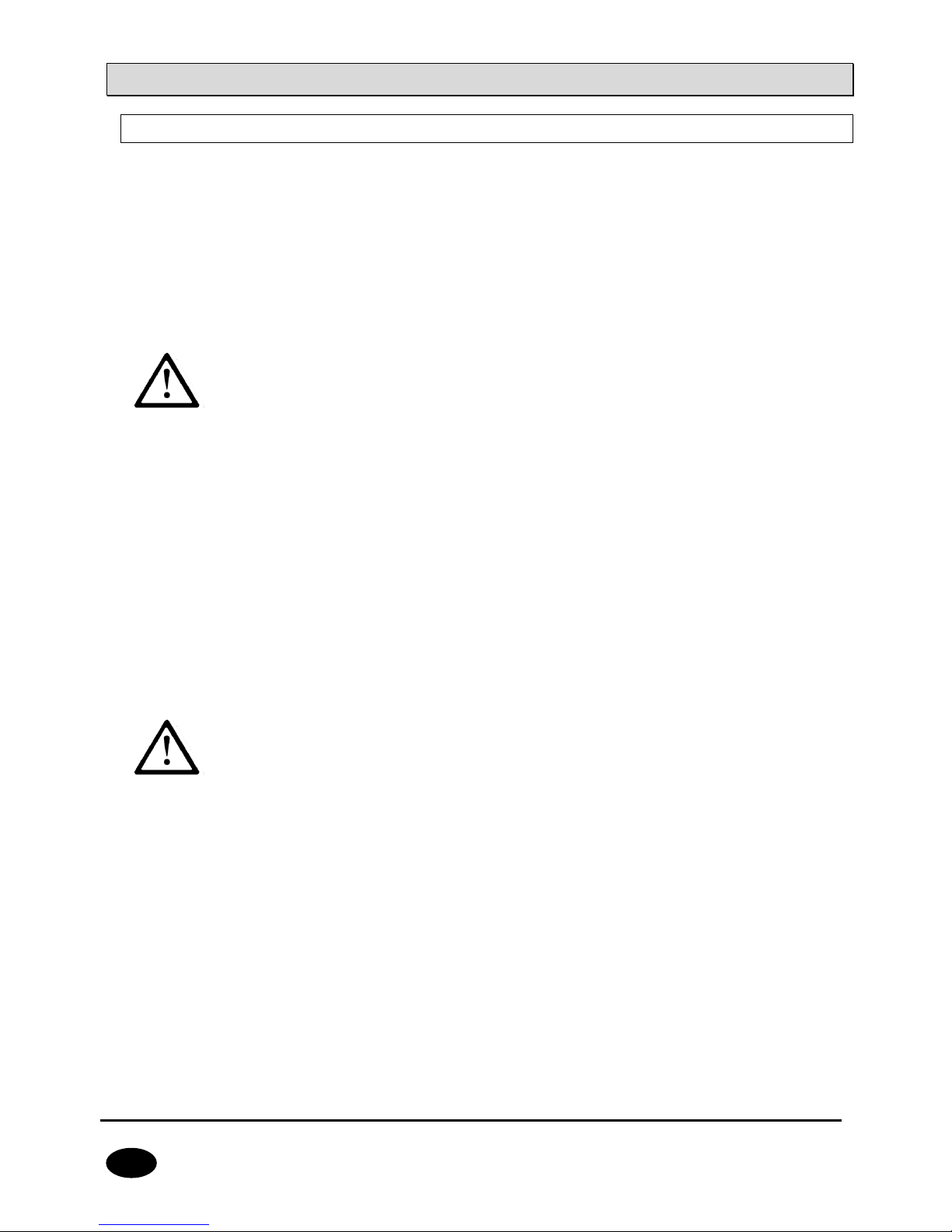
3.2. DESCRIPTION OF PCB ELEMENTS
Drawing 1. Description of PCB elements
1. GSM antenna connector (female SMA)
GSM antenna is delivered separately as one of the optional system components. It is
recommended to use antenna with cable that allows finding adequate position ensuring
optimal GSM range. The control panel is compatible with GSM antenna with male SMA
connector.
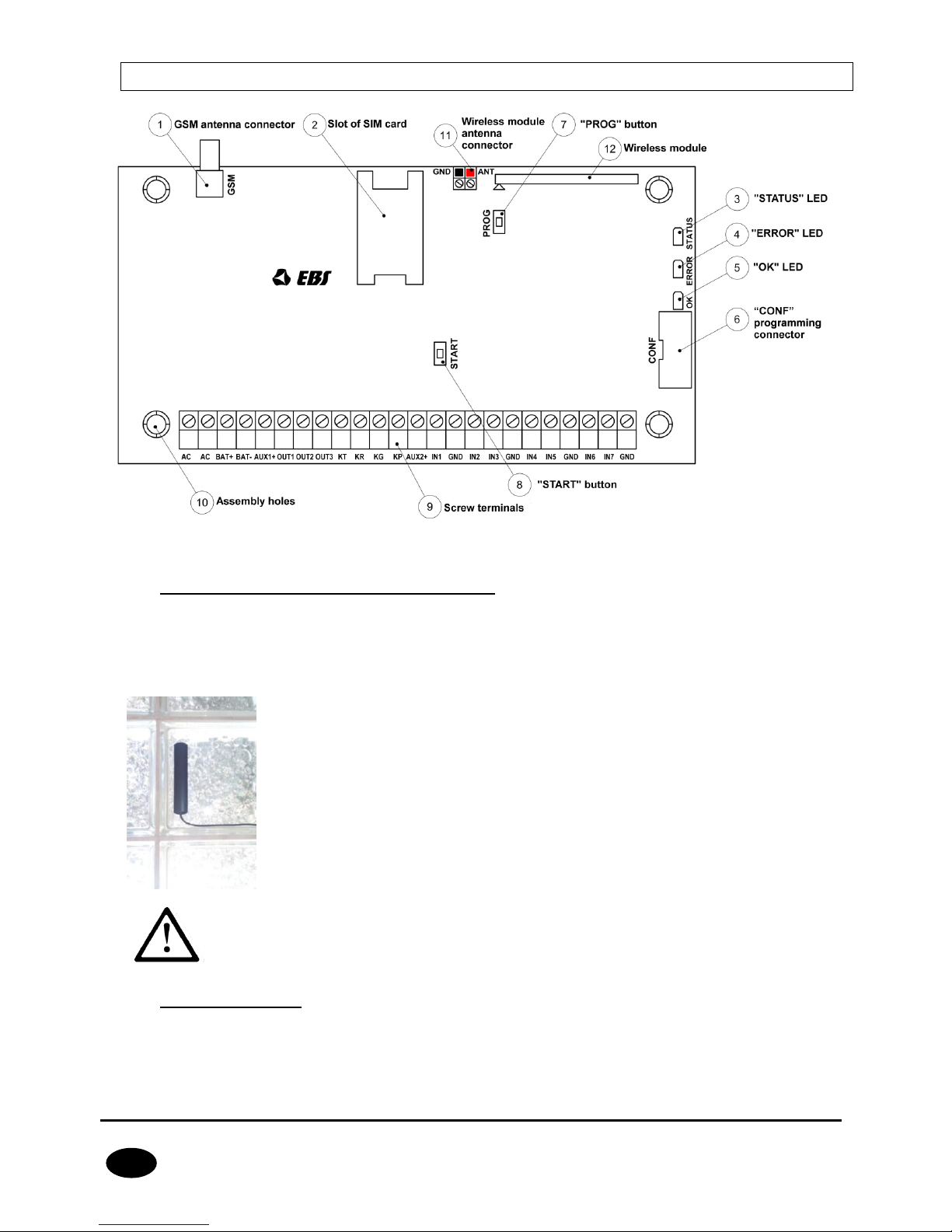
This type of antenna (photo on the left) should be install (self-adhesive
tape) on nonmetallic surface (plastic, glass etc.) in vertical position. The
high placement position , free of nearby objects will give You the best
possible GSM signal. Antenna shouldn’t be placed in close range to metal
objects (especially wires). Don’t put antennas into cases (above all in
metal cases). Antenna wire shouldn’t be flexed or rucked. There is not
recommend to extend antenna wire.
NOTE: Antenna shouldn’t be installed on alarm central case or in close
range to wireless receivers. It could decrease the signal range.
2. Slot of SIM card
The control panel is equipped with integrated GSM/GPRS/SMS transmitter. SIM card with
active GPRS transmission is necessary to communicate with the server. The card shall be
installed in the slot indicated in the drawing.
Page 12

CPX230NWB ALARM CONTROL PANEL – INSTALLER MANUAL 12 / 144
EN
NOTE: Before you insert the card, make sure that PIN code
authorization is deactivated, or PIN code is compliant with the code
programmed in the control panel. Default factory PIN code of the
control panel is 1111.
3. “STATUS” LED
Yellow LED diode. For the detailed description please refer to chapter 7.
4. “ERROR” LED
Red LED diode. For the detailed description please refer to chapter 7.
5. “OK” LED
Green LED diode. For the detailed description please refer to chapter 7.
6. “CONF” programming connector
“CONF” IDC10 connector allows the control panel configuration using dedicated
programming devices such as GD-PROG, MINI-PROG-BT, SP-PROG-BT and any
computer equipped with RS232 port (GD-PROG) or USB port (MINI-PROG-BT, SP-PROGBT) or Bluetooth (MINI-PROG-BT, SP-PROG-BT).
7. “PROG” button for default settings restoration
Pressing the button for 10s during connecting the control panel with power supply will
delete all users and restore the default admin and installer code. Default admin code is
1111, default installer code is 2222.
8. “START” button for battery activation of control panel without the mains
power supply
If the control panel is activated in the situation of power supply fault, press the button
after connecting the unit to the battery.
9. Screw terminals of the control panel
For detailed information on feeding, input and output connectors, please refer to chapter
3.3.
10. Assembly holes of the control panel (132x61mm hole span)
The above holes are intended for the control panel to be assembled in any type of casing.
In option a dedicated plastic OBDNA casing can be ordered (the casing includes
appropriate 230VAC/18VAC transformer).
11. Wireless module antenna connector
CPX230NWB included two types of antennas: internal and external dipole type.
Page 13
CPX230NWB ALARM CONTROL PANEL – INSTALLER MANUAL 13 / 144
EN
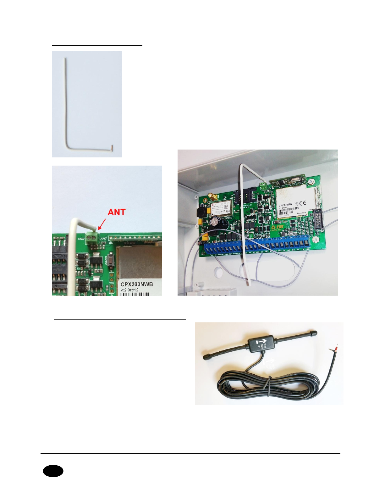
433MHz internal antenna
Internal antenna (photo on the left) can be used wherever required
compact size and antenna provides appropriate coverage level
detectors. Ending of the internal antenna without isolation should be
mounted in hot pole of the socket described as ANT (correct pole is
marked red on Drawing 1 and on photo below). Cold pole has been
filled with plastic element (marked as a black spot). Correct antenna
install position in the photo attached below.
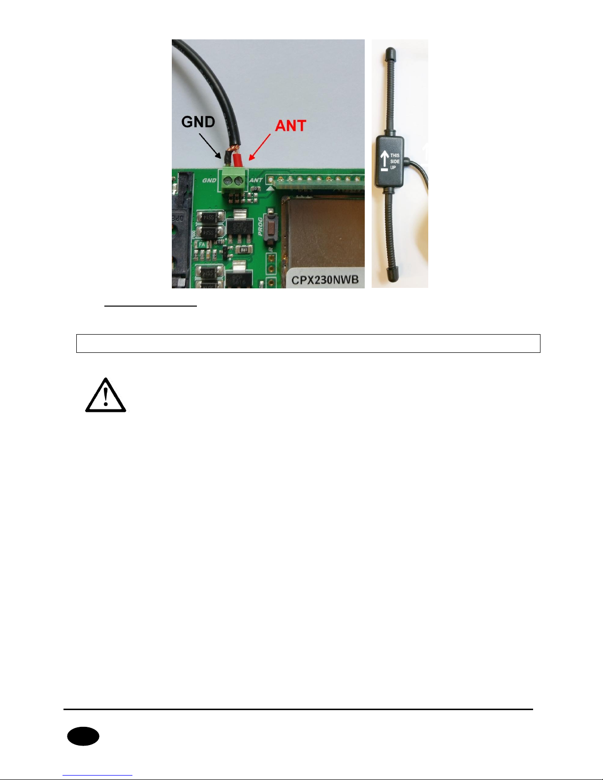
433MHz external antenna dipol type
NOTE: In order to improve the signal
coverage in harsh environments, you can
use an external antenna dipole type.
Antenna should be connected to GND and
ANT connector regarding to the color on
the endings of the wires. Before screw the
antenna, remove plastic element from
GND socket. Correct install position for
dipole antenna in the attached photo
below.
Page 14
CPX230NWB ALARM CONTROL PANEL – INSTALLER MANUAL 14 / 144
EN
12. Wireless module
The wireless module is used to receive signals from remote controls and wireless detectors.
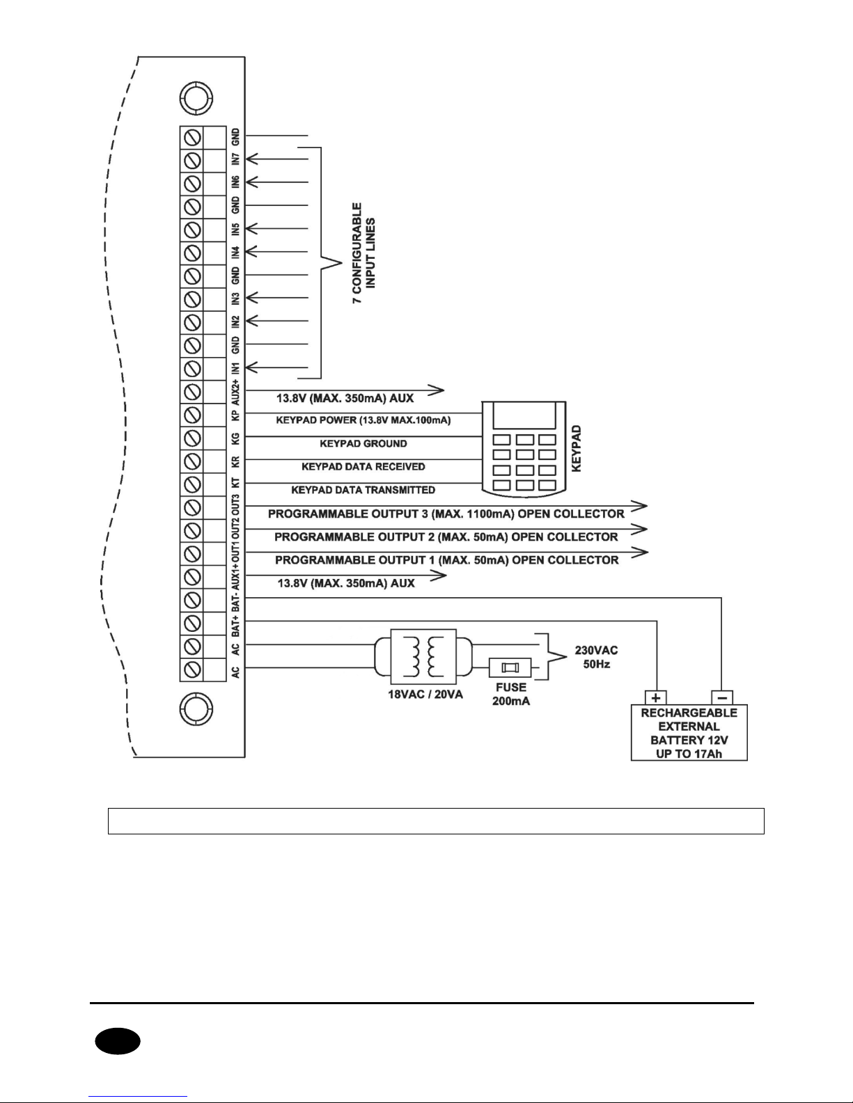
3.3. DESCRIPTION OF SCREW TERMINALS OF THE CONTROL PANEL
NOTE: Any assembly and installation works shall be carried out with
power supply off and battery disconnected.
Page 15
CPX230NWB ALARM CONTROL PANEL – INSTALLER MANUAL 15 / 144
EN
Drawing 2. Description of screw terminals of the control panel
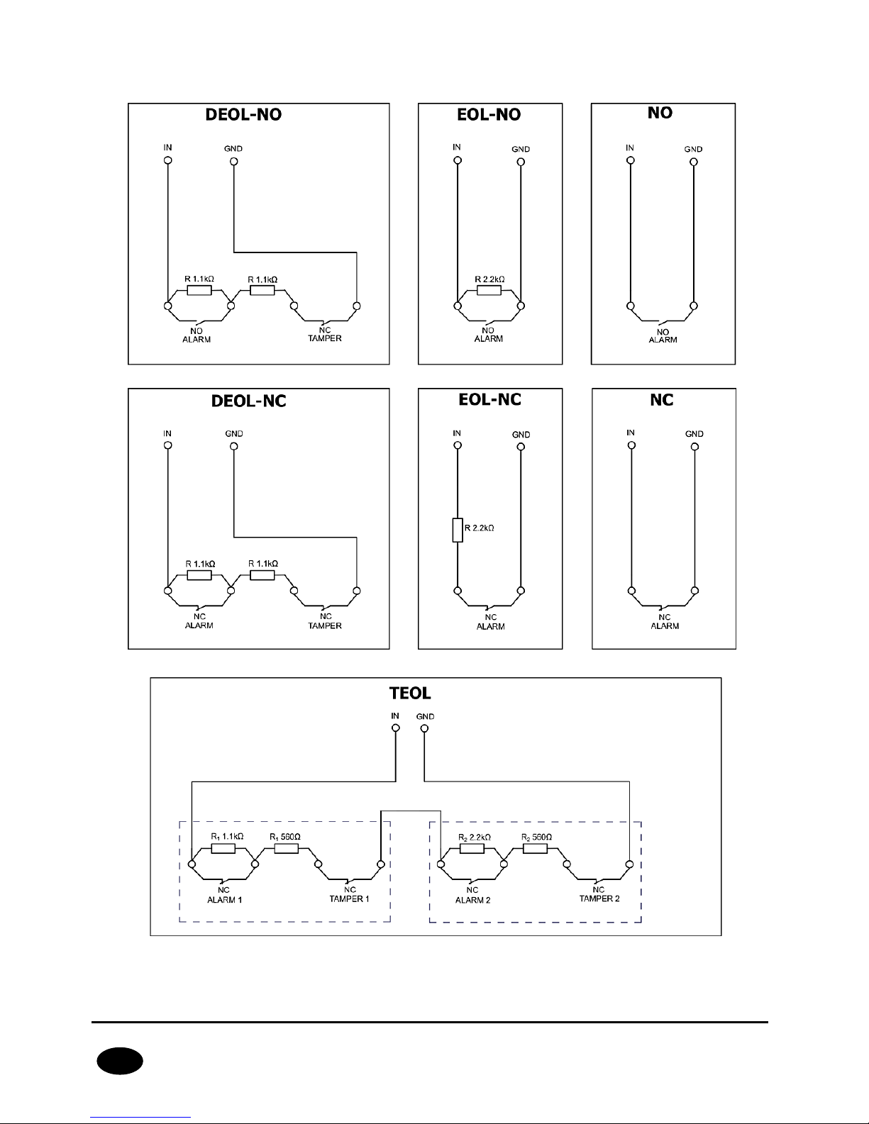
3.4. CONFIGURATION OF WIRED INPUT ZONES
All wired input zones are fully configurable and can operate as normally closed (NC)) or
normally open (NO) as well as with assigned parameters (EOL-NO or EOL-NC) using 2.2kΩ
resistors or with assigned double parameters (DEOL-NO or DEOL-NC) using 1.1kΩ
resistors. The TEOL configuration is used to double an alarm zone, i.e. connect two wire
detectors to one clamp at the central, and it is possible to detect alarms from detector 1
and detector 2 (see drawing 3), while signaling sabotage switch (tamper) open will be
common for both detectors.
Page 16
CPX230NWB ALARM CONTROL PANEL – INSTALLER MANUAL 16 / 144
EN
Both resistor types are included in the delivery of the control panel. Various configurations
of input zones are presented in the drawing 3.
Drawing 3. Configuration of input zones
Detector 1
Detector 2
Page 17
CPX230NWB ALARM CONTROL PANEL – INSTALLER MANUAL 17 / 144
EN
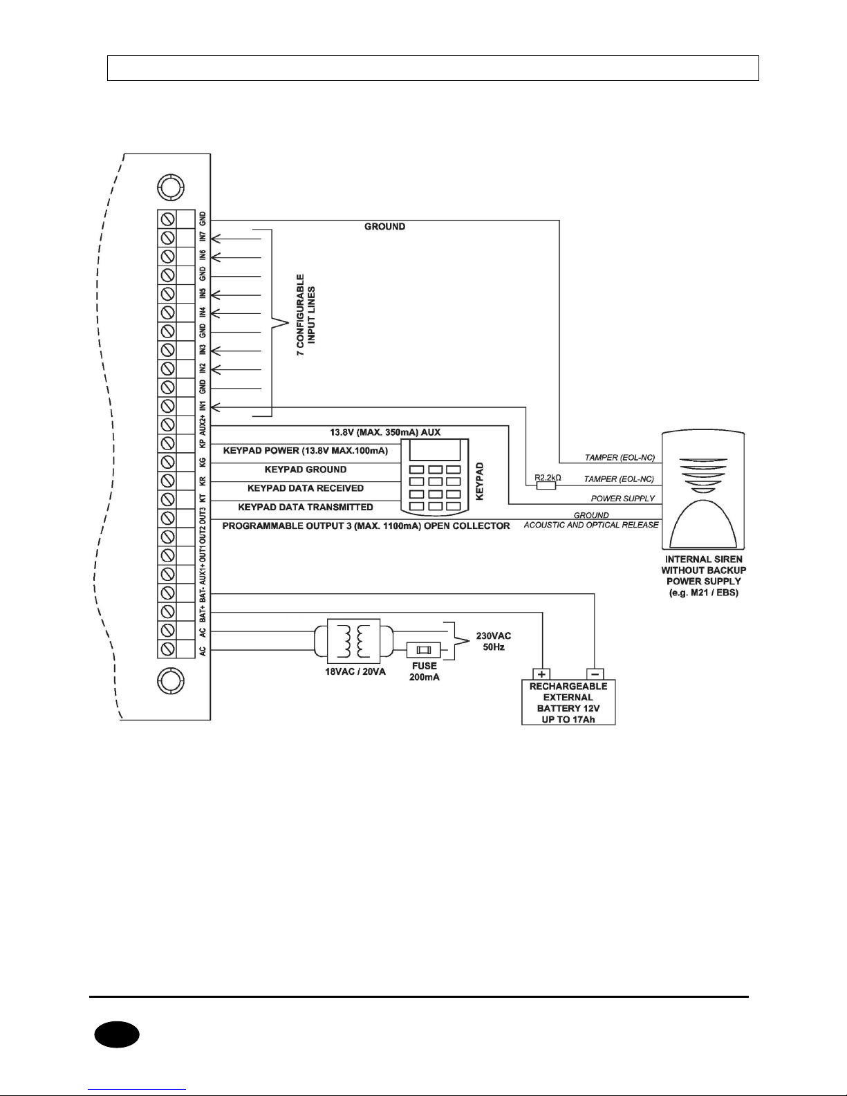
3.5. SAMPLE CONNECTION OF SIGNALING DEVICE
3.5.1. Internal signaling device without independent source of power
supply
Drawing 4. Sample connection of internal signaling device without independent source of power
supply
Page 18
CPX230NWB ALARM CONTROL PANEL – INSTALLER MANUAL 18 / 144
EN
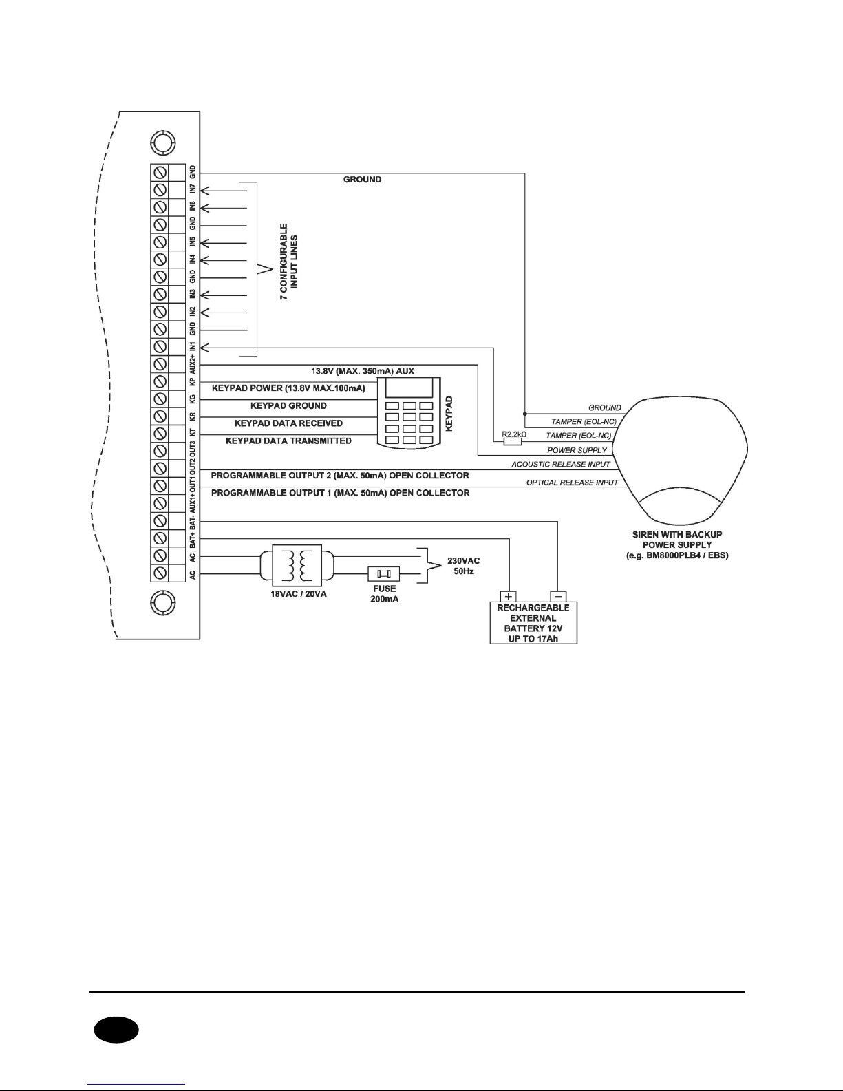
3.5.2. External signaling device with independent source of power
supply
Drawing 5. Sample connection of external signaling device with independent source of power supply
Page 19
CPX230NWB ALARM CONTROL PANEL – INSTALLER MANUAL 19 / 144
EN
3.6. KP32 KEYPAD
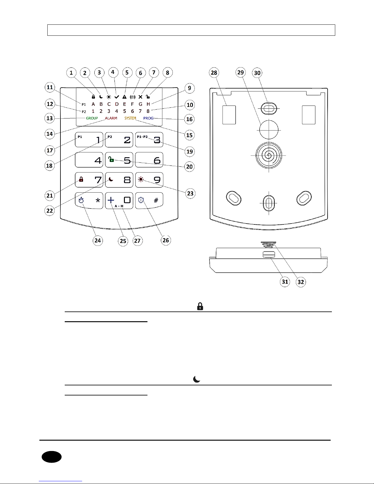
3.6.1. Description of keypad elements
Drawing 6. KP32 Keypad
1. FULLY ARMED mode arming symbol – indicated with diodes A (partition
P1) and 1 (partition P2)
Blinks slowly: exit time countdown,
Blinks quickly: entry time countdown,
Lit continuously: partition armed in full mode,
Not lit: partition not armed in full mode.
2. SLEEP Night mode arming symbol – indicated with diodes B (partition
P1) and 2 (partition P2)
Blinks slowly: exit time countdown,
Blinks quickly: entry time countdown,
Lit continuously: partition armed in night mode,
Page 20

CPX230NWB ALARM CONTROL PANEL – INSTALLER MANUAL 20 / 144
EN
Not lit: partition not armed in night mode.
3. STAY Day mode arming symbol – indicated with diodes C (partition P1)
and 3 (partition P2)
Blinks slowly: exit time countdown,
Blinks quickly: entry time countdown,
Lit continuously: partition armed in day mode,
Not lit: partition not armed in day mode.
4. READY symbol – indicated with diodes D (partition P1) and 4 (partition
P2)
Lit when all zones (without the “ignore when arming” option selected) are in nominal
condition (not triggered).
5. Partition input or output sabotage/failure symbol – indicated with diodes
E (partition P1) and 5 (partition P2)
Blinks quickly: no longer present, but there were failures/sabotage of inputs or outputs
assigned to the partition,
Lit continuously: there are failures/sabotage of inputs or outputs assigned to the
partition.
6. Partition alarm/alarm memory symbol – indicated with diodes F
(partition P1) and 6 (partition P2)
Blinks quickly: no longer present, but there were alerts from zones assigned to the
partition,
Lit continuously: there is an alarm from a zone assigned to the partition.
7. Line bypass symbol – indicated with diodes G (partition P1) and 7
(partition P2)
Lit when at least one zone belonging to the partition is locked out (bypassed).
8. DISARM Partition disarming symbol – indicated with diodes H (partition
P1) and 8 (partition P2)
Lit when the given partition is disarmed, e.g. in DISARM mode.
9. Diodes A-H (white)
A row of diodes used to indicate the status of partition P1 (example: when lit, “B” diode
means partition P1 is armed in SLEEP night mode).
10. Diodes 1-8 (white)
A row of diodes used to indicate the status of partition P2 (example: when lit, “3” diode
means partition P2 is armed in STAY day mode).
11. Partition 1 (“P1”)
The P1 symbol means partition 1, to which diodes from A to H are assigned.
Page 21

CPX230NWB ALARM CONTROL PANEL – INSTALLER MANUAL 21 / 144
EN
12. Partition 2 (“P2”)
The P2 symbol means partition 2, to which diodes from 1 to 8 are assigned.
13. “GROUP” diode
When this diode is blinking quickly, it means entering the user function in which either
zones or users are shown.
14. “ALARM” diode
When this diode is lit, it means a general system alarm (e.g. keypad sabotage, ALARM
button on the remote), where:
Blinks: alarm triggered in the past,
Lit continuously: current alarm.
15. “SYSTEM” diode
When this diode is lit, it means a system failure, e.g.: power failure, battery failure,
ATS connection failure, power output failure, clock loss, keypad sabotage.
Blinks – it means that control panel memory stores failures that have passed,
Lit continuously – there is a failure in the system that has not been repaired,
Not lit – there are no failures in the system.
16. “PROG” diode
Blinks slowly – the service function is enabled (a user function),
Blinks – data will be entered,
Lit continuously – installation engineer's service mode is enabled.
17. Button 1 “P1”
A function button that supports the arming of partition P1.
18. Button 2 “P2”
A function button that supports the arming of partition P2.
19. Button 3 “P1+P2”
A function button that supports simultaneous arming of partitions P1 and P2.
20. Button 5 (open padlock)
A function button that supports disarming.
21. Button 7 (locked padlock)
A function button that supports the arming in full mode.
22. Button 8 (moon)
A function button that supports the arming in night mode (SLEEP).
23. Button 9 (sun)
A function button that supports the arming in day mode (STAY).
24. Button “*” (flame)
Page 22

CPX230NWB ALARM CONTROL PANEL – INSTALLER MANUAL 22 / 144
EN
FIRE function button - press for about 3 sec to generate a fire alarm.
25. Button 0 “+”
HELP function button - press for about 3 sec to generate a medic alarm.
26. Button “#” (shield)
PANIC function button - press for about 3 sec to generate a panic alarm.
27. Button 0 (A - H)
A function button which enables switching between groups.
28. Screw connectors
Connectors for connecting cables leading from keypads to the alarm central.
29. Cable entry hole
A place for inserting connection cables.
30. Installation holes
The keypad has four oval installation holes for proper mounting of the keypad.
31. Casing opening latch
It is recommended to use a 2.5 - 5 mm flat screwdriver for opening the casing. Slide it
lightly into the indicated hole and make a slight leverage movement towards the back
of the casing.
32. Sabotage switch
After installing the keypad, the contact of this switch is closed. Unauthorized keypad
removal will result in sending a signal to the alarm central. A spring is mounted on the
switch lever to compensate for uneven surfaces.
3.6.2. Keypad specification
Power supply voltage:
10 – 13.8 VDC
Power consumption:
typ. 20 mA, max. 70 mA
Keypad weight:
70g
Size of casing:
99 x 82 x 19 mm
Keypad type:
LED, 16 status LEDs, 4 mode LEDs (GROUP,
ALARM, SYSTEM, PROG)
Button layout:
Standard telephone keypad 3 x 4 buttons
3.6.3. Keypad installation
1. KP32 keypad is intended for inside installation, on dry and even surface. Usually, it is
installed on wall, near the entrance door, 120 -140 cm high from the ground.
2. To open the keypad casing – insert a flat screwdriver in the bottom part of the casing
and press the latch. Then carefully take both parts of the casing apart, starting from
the casing’s bottom.
3. Mark and drill holes in the wall to install the rear part of the casing.
Page 23

CPX230NWB ALARM CONTROL PANEL – INSTALLER MANUAL 23 / 144
EN
4. Screw the rear part of the casing to the wall. The attached 4 screws with dowels are
designed for concrete base. For other substrates should choose the appropriate
screws individually.
5. Connect cables joining the keypad with the alarm control panel. Keypad terminals
marked: KT, KR, KP, KG shall be connected with KT, KR, KP, KG terminals in the
alarm control panel (see drawing 2.).
6. Assembly the rear part of the casing with the front one starting from the casing’s top.
Make sure that the keypad is well assembled and sabotage switch is pressed in.
3.6.4. Addressing devices connected to the keypad bus
Each keypad to be connected to the bus must have its own individual address from the 1 to
3 range. Addresses must not repeat (the control panel does not support devices having
identical addresses). It is recommended that consecutive addresses be assigned starting
from 1. In keypads, the address is set by software means. By default, address 1 is set.
Programing keypad address:
1. Remove the keypad from the wall (tamper switch should be open).
2. Press and hold buttons and or or at the same time until
the corresponding diode turns on (A for address no. 1, B for no. 2, and C for no.
3).
3. After a few dozen seconds programmed keypad will be worked properly with the
new addresses.
3.7. WIRELESS KEYPAD KP2W
The wireless keypad KP2W was designed to work with the hybrid control panel CPX230NWB.
There is a possibility to add up to 32 of these keypads, however each of them occupies one
of 32 input zones. For instance, if you add 5 keypads KP2W, there leave 27 input zones
which can be used for other devices (e.g. detectors).
The transmission between the keypad and the control panel is protected with changing code
and encrypted. The device sends to the control panel a cyclic test transmission and lack of it
will be signaled in the system as a breach of the zone, to which the keypad is assigned to.
The keypad detects and alerts low battery voltage, as well as opening of the case or its
removal from the surface.
The keypad has also an NC input for connecting additional door opening detector.
Keep in mind, that the wireless keypad KP2W uses one-way transmission and
cannot receive communication from the control panel. Therefore, we suggest to set
one of the control panel outputs in arming/disarming signalization (so-called chirp) and to
connect an acoustic signaler to this output. This will facilitate use of the panel.
We recommend to have at least one wire keypad KP32 installed in the alarm system in order
to set parameters of the control panel, display system status and change user codes. We
also recommend to use AVA application with the control panel CPX230NWB to facilitate
controlling operation of our alarm control panels.
Page 24
CPX230NWB ALARM CONTROL PANEL – INSTALLER MANUAL 24 / 144
EN
3.7.1. Adding KP2W to the system
The wireless keypad KP2W can be introduced to the alarm system memory in
a manner similar to wireless sensors. There are two methods available:
Using KP32 keypad, see chapter 4.3.16.1. Wireless sensors configuration.
Using software “GPRS Transmitter configurator”, see chapter 6.3.2. Wireless zones.
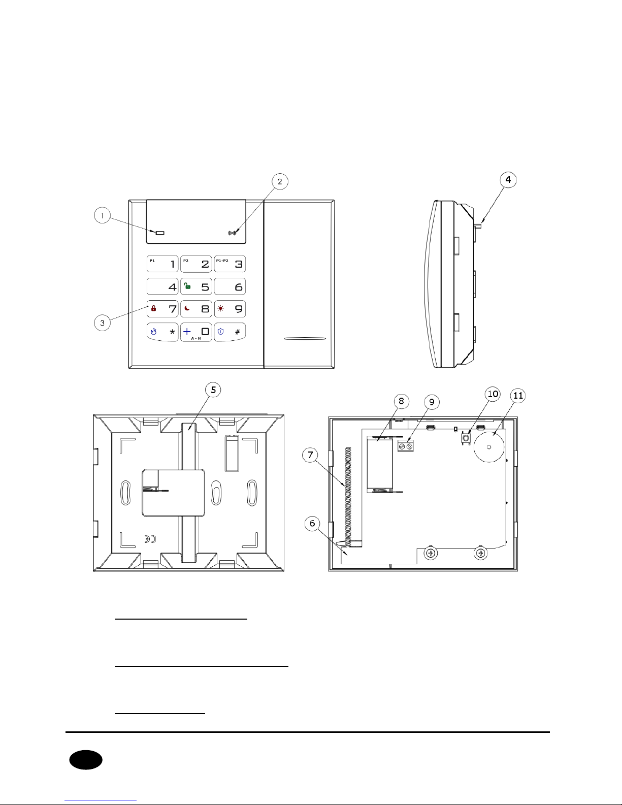
3.7.2. Description of keypad elements
Drawing 7. KP2W Keypad
1. Low battery LED (RED)
On – battery is low,
Off – battery O.K.
2. Data transmission LED (BLUE)
Blinks – data transmission in progress
Off – no data transmission
3. Keypad buttons
Page 25

CPX230NWB ALARM CONTROL PANEL – INSTALLER MANUAL 25 / 144
EN
Buttons on the KP2W keypad function the same as on the KP32 keypad (see section
3.6.1 Description of keypad elements - points 17 to 27). After first pressing any
button, the keypad is backlit. After a few-second idle time, backlight gets
automatically dimmed.
4. Anti-sabotage switch
After the keypad is assembled the anti-sabotage switch is closed. Unauthorized
disassembly of the keypad will send the message to the alarm control panel.
5. Canal for wires
6. Mainboard
7. Antenna 433,92MHz
8. Battery
Lithium Battery CR123A 3V.
9. Screw Connector
Connector for wired magnet contact - open door switch. Keep closed if not used.
10. Sabotage sensor (tamper)
11. Buzzer
3.7.3. Keypad specification
Power supply:
1 battery CR123A 3V
Working time:
3 years*
Frequency of operation:
433.92 MHz
Communication range:
up to 500m (open air)
Communication:
one way
Average current consumption:
30 μA
Operation temperature:
-10 °C +55 °C
Alarm inputs:
1, NC type
Dimensions:
125 x 102 x 33 mm
Wight without battery:
150 g
*Working conditions: test transmission every 15 minutes, keyboard use (arming/disarming) 2 times a day,
open door switch closed, working temperature 20°C
Page 26
CPX230NWB ALARM CONTROL PANEL – INSTALLER MANUAL 26 / 144
EN
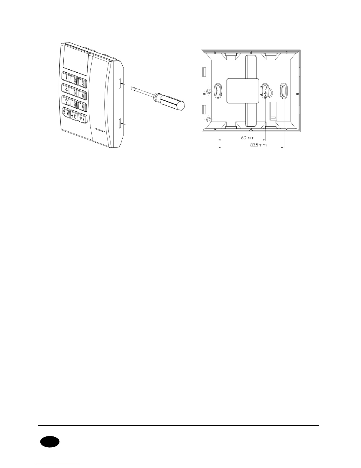
3.7.4. Keypad installation
Drawing 8. Case opening latches and mounting holes
The keyboard KP2W is intended for indoors installation on dry and smooth surface. Usually
it is located on the wall, by the front doors, 120-140 cm above the ground.
1. Open the keypad case – insert a flat-head screwdriver in the hole in the bottom part
of the case and press the latch. Then, press the other latch and carefully draw aside
both parts of the case, starting from the bottom one.
2. Mark and drill holes in the wall for assembly of the back part of the case.
3. Screw down the back part of the case.
4. Put in a CR123A battery as per markings on the plate. The incorrect placement of the
battery will result in the failure to start the device. As soon as the battery is inside,
two LEDs (for battery – red one, for transmission – blue one) and keys backlight will
light up temporarily.
5. Put together the front part of the case with the back one starting from the top of the
case. Make sure that the keypad is properly assembled and the tamper switch is
pressed down.
3.7.5. Door opening sensor
The keyboard KP2W is equipped with a feature enabling connection of opening sensor
(reed relay), which can be used as a door opening sensor.
The NC connector (normally closed) used in this case should be shorted, if the possibility to
connect the sensor is not used. The connector can be found on the keypad board and
labelled 9 in Drawing 7.
This sensor in the alarm system CPX230NWB will have assigned the same zone number as
the keypad.
Page 27
CPX230NWB ALARM CONTROL PANEL – INSTALLER MANUAL 27 / 144
EN
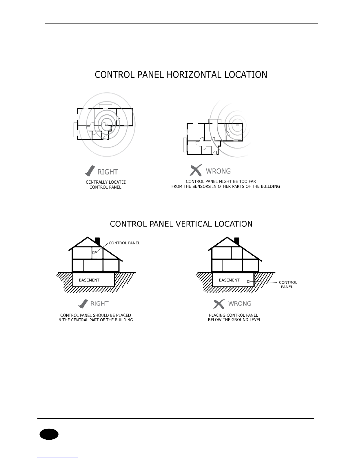
3.8. CONTROL PANEL LOCATION
The control panel should be located in the control panel part of the object. The central
location of the control panel usually provides good communication with all wireless
detectors. See drawings 9 and 10.
Drawing 9. Control panel horizontal location
Drawing 10. Control panel vertical location
The radio waves are attenuated by walls and other obstacles. Lowest attenuation have
wallboards and wooden frame. Medium attenuation have light concrete and brick walls.
Reinforced concrete and metal latticed plaster have the greatest attenuation. The drawing
11 shows the signal loss through various different types of materials. (NOTE: the figure is
simplified, only for illustration – remember that radio waves propagate multidirectionally).
Page 28
CPX230NWB ALARM CONTROL PANEL – INSTALLER MANUAL 28 / 144
EN
Wallboards and wooden frame
0-10% loss
Light concrete or brick walls
5-35% loss
Rainforced concrete or metal latticed plaster
30-90% loss
Drawing 11. Signal loss through construction materials
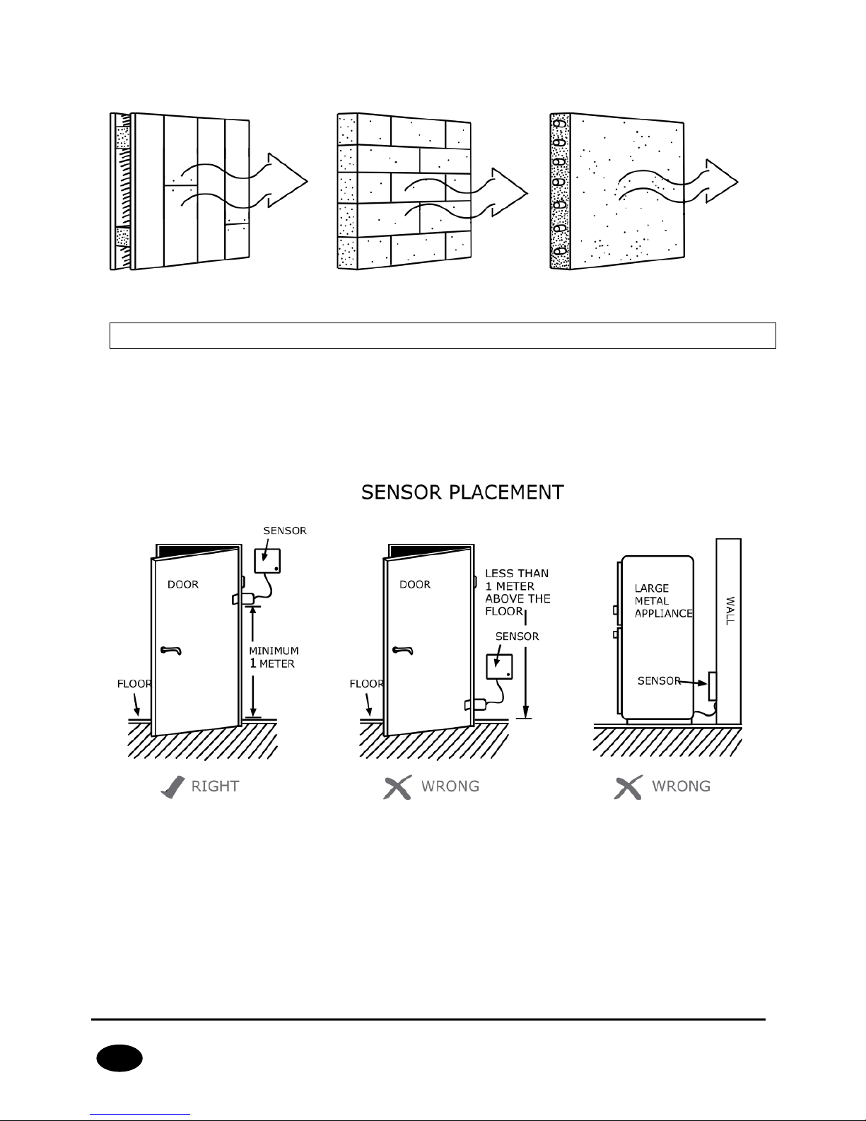
3.9. WIRELESS DETECTORS INSTALLATION RECOMMENDATIONS
The wireless detectors should be located relative to the panel in such a way as to be on the
same side of the control panel as the radio antenna and electronic components. In this way
you get the best radio coverage.
Additional installation tips describes the drawing 12.
Drawing 12. Sensor placement
Page 29

CPX230NWB ALARM CONTROL PANEL – INSTALLER MANUAL 29 / 144
EN
4. SERVICE MODE
Note: The following operations can be performed only using the main
keypad KP32.
Service mode is intended for configuration of basic parameters related to zones, outputs and
partitions. It allows to manually, using a keypad, program all correlations necessary for
correct system operation.
After the service mode is initiated a number of service functions are available. To configure
the system, enter the number of function and its arguments, related to the function, as
following:
<Number of function> <Argument>
where:
Number of function –
a number of one of available service functions,
Argument –
the argument of a given service function (of BIN or DEC type).
Each service function has one of two argument types: binary (BIN) or decimal (DEC) .
Handling each of the two types of arguments is presented below:
Binary type (BIN)
When the binary argument type function is entered, the current option status is displayed
with LEDs relevant to a given option of the function on/off. Press 1 to 9 buttons to change the
status of LED and the option it corresponds to. Options 10 – 16 may be changed by long
press (for 2 sec) the buttons 0 – 6. The installer can change the option status as many times
as they want. When the desired status is set, press to confirm or to exit without
saving changes.
Decimal type (DEC)
Service function that accepts decimal type arguments can also accept any length strings of
decimal numbers, not exceeding the maximum length pre-defined for the function. When a
character is entered, a cursor gets automatically ready for entering the next character. Press
to save currently entered changes and exit the service function, press to cancel
entered changes and exit the service function. Before you press any key on a keypad, the
currently programmed parameter value is displayed. It is presented by displaying subsequent
digits of the parameter with a short pause in between. When all digits of the parameter are
displayed, the pause is longer.
After pressing the numerical button, the lately entered digit is displayed on a keypad. The
way the digits are displayed on a keypad is presented in the table below:
Page 30

CPX230NWB ALARM CONTROL PANEL – INSTALLER MANUAL 30 / 144
EN
4.1. ACTIVATION OF SERVICE MODE
To activate the service mode the installer code authorization is required.
<Installer code>
3 beeps will confirm the correct input of the code and function number. PROG LED on will
inform that currently, the user is in service mode. When any service function is entered,
PROG LED will be blinking. After exit from the function, PROG LED will be lit constantly
again, informing that the user is in the main service mode menu.
4.2. EXIT FROM SERVICE MODE
To exit the service mode press and confirm with . Using that function will trigger
the control panel’s reset using configured parameters.
The device will exit test mode automatically after 5 minutes without pressing the buttons
and system will restart.
4.3. INSTALLER MENU
After enter the service mode You get permission to configure alarm central. By this
commands You can get into some menu sections (more information about procedures You
will get in chapters bellow):
Installer code change
Power loss time report
Number entered
LEDs on
0
1 2 3 4 5 6 7 8
1
1 2 3 4 5 6 7 8
2
1 2 3 4 5 6 7 8
3
1 2 3 4 5 6 7 8
4
1 2 3 4 5 6 7 8
5
1 2 3 4 5 6 7 8
6
1 2 3 4 5 6 7 8
7
1 2 3 4 5 6 7 8
8
1 2 3 4 5 6 7 8
9
1 2 3 4 5 6 7 8
10
1 2 3 4 5 6 7 8
11
1 2 3 4 5 6 7 8
12
1 2 3 4 5 6 7 8
13
1 2 3 4 5 6 7 8
14
1 2 3 4 5 6 7 8
15
1 2 3 4 5 6 7 8
Page 31

CPX230NWB ALARM CONTROL PANEL – INSTALLER MANUAL 31 / 144
EN
Reset to default settings
System options
Users remote manager
Expanded system options
<code length>
Access code length
<time[sec]>
Alarm history notification disabling delay
<time[h]>
Time to detect loss of wireless detectors
<1/2/3><number
Entering and changing ACN numbers
<1/2/3>
Deleting ACN numbers and set-up
Switch off periodic repeating of wireless detectors
loss events
<time[h]>
Periodic repeating of wireless detectors loss
events
<XX> <Y> <Z>
Zones configuration
<XX> <Y> <Z>
Outputs configuration
<XX> <Y> <Z>
Partitions configuration
<XX> <Y>
Wireless zones configuration
<XX> <Y>
Remote controllers configuration
<XX> <Y>
Emergency buttons
4.3.1. Installer code
The installer code can be changed here. 3 beeps will confirm the successfully entered
function.
<Installer code> <Installer code>
where:
Installer code –
new installer code (from 4 to 7 digits)
You can press any time to exit without saving changes.
4.3.2. Power loss
The function determines time in seconds after which failure is to be reported. The
function’s argument is of decimal type. 3 beeps will confirm the successfully entered
function.
To change /configure the time:
Page 32

CPX230NWB ALARM CONTROL PANEL – INSTALLER MANUAL 32 / 144
EN
<Time>
where:
Time –
time in seconds
You can press any time to exit without saving changes.
4.3.3. Reset to default settings
That function resets the settings to their default configuration, accessible from the service
mode level. Additionally, the function sets the default output options and default installer
code. The wireless detectors and remote controls are not deleted.
In order to protect the settings against accidental modification, the function is to be
confirmed with installer code. 3 beeps will confirm the successfully entered function. Using
that function will trigger the control panel’s reset using default parameters.
<Installer code>
You can press any time to exit without saving changes.
4.3.4. System options
That function allow to switch on and switch off additional options of the system. The
argument of the function is BIN type. By pressing 1, 2, 3, 4, 5, 6, 7 and 8 keys, you can
switch on/off proper option. 3 beeps will confirm the successfully entered function.
<Options>
Where:
Options – number of option (BIN type parameter):
1 – Enable faults memory indication – when is switched off, LED SYSTEM does not
show by blinking the faults that are not active; you can display inactive faults by
choosing “faults memory” user function.
2 – Disable ATS monitoring. If this option is enabled, ATS failure isn’t signaled to the
user in any way on the keypad and it doesn’t cause arm prevention.
3 – Request arming confirmation (by pressing #) in case of failure. If this option is
enabled, the user is additionally notified of system failures when arming the system.
The wired keypad produces a continuous sound, the ALARM and SYSTEM diodes
start flashing slowly and error codes are displayed on diodes 1–8 (see User’s Manual,
section 7.6 Arming the system with a fault). To arm the system press # button.
Information on failures and triggering are available after entering with the use of the
wired keypad the user's function: failure memory and current state of inputs. In the
case of a system failure, if the option is disabled, the arming lock will be
automatically omitted.
4 – Access to alarm and fault memory requires authorization. If this option is
enabled, checking alarm memory and fault memory is available only after a user
code is entered. This option must be enabled in order to comply with EN 50131
standard requirements for Grade 2.
Page 33

CPX230NWB ALARM CONTROL PANEL – INSTALLER MANUAL 33 / 144
EN
5 – Alarms and inputs interlocking states are not displayed. If this option is enabled,
alarms and zone state are not displayed on the keypad. This option must be enabled
in order to comply with EN 50131 standard requirements for Grade 2.
6 – Temporary keyboard lock after three access failures. If this option is enabled, the
keypad will be blocked for 90 seconds, after entering an invalid code three times.
After this period, another lock will occur after entering a wrong code three times.
The counter of invalid codes will be reset after a correct code is entered (e.g. after
entering invalid code two times). This option must be enabled in order to comply
with EN 50131 standard requirements for Grade 2.
7 – Use duress code. Duress code is used to inform the monitoring station about a
distress event. Each user has his own duress code.
You can press any time to exit without saving changes.
4.3.5. Users remote management
That function allow to switch on or switch off remote users management. The argument of
the function is BIN type. By pressing key 1, you can switch on/off option. 3 beeps will
confirm the successfully entered function.
<Options>
Where:
Options – number of option (BIN type parameter):
1 – enable/disable users remote management.
You can press any time to exit without saving changes.
4.3.6. Expanded system options
An additional system function used to turn individual options on or off. The argument of
this function is of the BIN type. 3 beeps will confirm the successfully entered function.
<Options>
Options – option number:
1 – Premises lock. This function turns off the ability to arm the control panel. When
this function is turned on, the user will not be able to arm the site by any way (i.e.
SMS/GPRS, remote, arming inputs, schedules, wired keypad, wireless keypad).
Disarming the system is possible, however. Attempts to arm will be rejected by the
control panel.
2 – Defaults restoral lock. This function allows the user to turn off the ability to
restore the factory-default installation engineer code. However, when restoring
default settings using the Configuration, when the "Restore device’s default settings"
option is selected, a window with a request to enter the installer code or service
code (ATS) will appear.
When this function is turned on, the Manufacturer recommends that installer code
and service code (ATS) code are changed.
Page 34

CPX230NWB ALARM CONTROL PANEL – INSTALLER MANUAL 34 / 144
EN
NOTE: If newly set codes are lost, it will be necessary to send the blocked devices
to the EBS technical service.
3 – Allow quick arming without user authorization. When this function is turned on,
it is possible to quickly arm the system using a keypad, without the need to enter
the user authorisation code.
4 – After disarming disable alarm history notification. With this option checked, after
disarming the system (partition), past alarms from zones assigned to partition (F
diode blinking - partition 1, 6 diode - partition 2), after assigned delay time, (refer
to chapter 4.3.8) will cease to be shown on the keypad (diodes will turn off). The
user will retain access to state of the alarm memory from inputs, by entering the 3#
function, until he chooses to delete it. If the system is armed, and the alarm caused
by any 24-hour zone will occur, then the fault memory can be turned off by arming
and disarming the system (if this option is checked) or by entering the 3# keypad
function and deleting the memory.
5 – Prevent arming using wired keypad when inputs are triggered or sabotaged. If
this option is selected, you can’t arm the system with KP32 if the detectors have
been triggered or tampered with. Triggering/tampering with any detector assigned
to the system is signalled by the diodes READY – D going off – in the case of a
detector assigned to Partition 1; 4 in the case of a detector from Partition 2. If the
system has been broken into two partitions, you can’t arm the control panel even, if
the detector has been triggered/tampered within only one of them. When
attempting to arm the system, the wired keypad emits a high one-second sound
and, at the same time, the diodes GROUP, ALARM, SYSTEM and PROG will go on for
about 4 seconds. System failures do not affect this option.
NOTE: This option is available since the firmware version 2.8.8.
You can press any time to exit without saving changes.
4.3.7. Access code length
The function enables setting the length of the administrator and user codes (the change
applies to all users). The code range is from 4 to 7 digits. By default, this value is set to 4.
<code length>
Where:
code length – code length code from the range of 4 to 7.
Reducing the code length is possible only if the shortened user codes do not
conflict with each other.
Example:
There are 5-digit codes in the CPX database – 44440, 44444, and 44449. It will not be
possible to shorten the code to 4 digits due to the conflict of identical resulting codes.
The change will not be accepted, which the keypad will signal with a several seconds
long continuous sound. In such a case, one solution is to delete a user or users who
have similar codes.
Page 35

CPX230NWB ALARM CONTROL PANEL – INSTALLER MANUAL 35 / 144
EN
4.3.8. Alarm history notification disabling delay
<time[sec]>
This function is only available after checking "After disarming disable alarm history
notification" option. It sets the delay time in seconds, after which the alarm memory will no
longer be shown on the keypad. It means, that when the system is armed, and there will
be violation of input zones shown by the F and 6 diodes blinking, then after disarming and
previously defined time the diodes will turn off. The alarm memory will still be accessible
with 3# function, until the user decides to delete it.
4.3.9. Time to detect loss of wireless detectors
This function allows you to set the time after which a notification is sent to the monitoring
station about the loss of the wireless detector.
<time [h]>
The time is expressed in hours. The default value is 6 hours, the minimum is 2 and the
maximum is 24.
NOTE: This option is available since the firmware version 2.8.8
1. If the user code in the CPX database is shorter than the defined
value, then '0' will be added to the codes at their ends:
Example: If the code 1234 exists in the database, then after code
length is changed to 6 digits, the code will appear as 123400.
2. If a user code in the CPX database is longer than the defined
value, then the access code will be the "n" first digits, according
to the value set.
Example: If the code 1234567 exists in the database, then after
code length is changed to 5 digits, the code will appear as
12345.
3. For codes under duress:
If the code 12345 exists in the database, then after code length
is changed to 7 digits, the code will appear as 1234500, so the
code under duress will be 1234501.
If the code 12345 exists in the database, then after code length
is changed to 4 digits, the code will appear as 1234, so the code
under duress will be 1235.
Page 36

CPX230NWB ALARM CONTROL PANEL – INSTALLER MANUAL 36 / 144
EN
4.3.10. Switch off periodic repeating of wireless detectors loss events
This function allows you to switch off only the option periodic repeating to the monitoring
station events about loss of the wireless detector.
NOTE: This option is available since the firmware version 2.10.0
4.3.11. Periodic repeating of wireless detectors loss events
This function allows you to switch on periodic repeating of wireless detector loss events to
the monitoring station (starting from the first loss).
<time [h]>
The time is expressed in hours. The default value is 6 hours, the minimum is 2 and the
maximum is 24.
NOTE: This option is available since the firmware version 2.10.0.
4.3.12. ACN numbers for communication in the Contact ID format
When transmitting data in the Contact ID format, you can set up individual numbers for
system account identification – ACN0, and its subsystems accounts, partition 1 – ACN1 and
partition 2 – ACN2. This allows you to determine, which part of the system the signal from.
NOTE: This option is available since the firmware version 2.9.0
4.3.12.1. Entering and modification of ACN Numbers
If ACN0 number is entered, it is attached to each system event sent to the monitoring
station. System events are those that provide information about the entire system, i.e.
power failure, modem reset, clock loss.
If numbers ACN1 and ACN2 are entered, the ACN1 is attached to each non-system event
(with partition ID 1 and/or 2) with information about partition 1, and to events with
information about partition 2 – the ACN2. Non-system events are those with information
about particular partitions, i.e. about arming/disarming partitions 1 and/or 2, alarms
activated by triggering the detectors assigned to partitions.
In order to define numbers, press the keypad:
<button 1/2/3> <number>
Where:
button 1 – setting or changing the ACN1 number of the partition 1 account
button 2 – setting or changing the ACN2 number of the partition 2 account
button 3 – setting or changing the ACN0 number of the system account
number – ACN number – any four hexadecimal characters
Page 37

CPX230NWB ALARM CONTROL PANEL – INSTALLER MANUAL 37 / 144
EN
If diodes 1, 2 and 3 are turned off, it means the ACNs have not been set up. The ACN0
number is set by pressing button 3, keying in four hexadecimal characters and pressing the
confirmation button . The ACN1 and ACN2 numbers are set in the same way. If the
diodes are turned on, pressing buttons 1, 2, 3 allows you to see the assigned numbers and
to change them if necessary.
NOTE: If you have assigned an account number only to one of the
partitions, the same number will be automatically assigned to the other
partition and to the system.
4.3.12.2. Delating the ACN numbers and changing option settings
To delete numbers or set up system event messages, press:
<Button 1/2/3>
Where:
button 1 – means deleting the ACN0 number sent to the system account
button 2 – means deleting the ACN1 and ACN2 numbers sent to the partition 1 and 2
accounts
button 3 – set-up how system events are to be sent, where:
o diode 3 is off – system events are sent only to the system account
o diode 3 is on – system events are sent to all accounts
NOTE: If you have deleted the ACN0 number, the ACN1 and ACN2
numbers will be also deleted.
4.3.13. Zones configuration
Wired and wireless zones can be configured using complex service functions, after
activation of which, all the parameters related to the relevant zone can be given
subsequently or in a form of series of service functions that configure one zone-related
parameter. Additional configuration of wireless zones is described in item 4.3.16.
Codes of zone configuration functions are defined as per the following pattern:
<XX> <Y> <Z>
where:
XX –
zone number from 01 to 32, the table below shows zones names and their
corresponding numbers:
Name
A1
A2
A3
A4
A5
A6
A7
A8
B1
B2
B3
B4
B5
B6
B7
B8
C1
C2
C3
C4
C5
C6
C7
C8
D1
D2
D3
D4
D5
D6
D7
D8
Number
1 2 3 4 5 6 7 8 9
10
11
12
13
14
15
16
17
18
19
20
21
22
23
24
25
26
27
28
29
30
31
32
Entering number 00 will change the parameters for all zones in the system,
Y
– number of parameter related to a given zone,
Z
- number (or value) of the next parameter.
Page 38

CPX230NWB ALARM CONTROL PANEL – INSTALLER MANUAL 38 / 144
EN
For Y=0 – complex function, the initiation of which configures the parameters listed
below as another set of parameters;
Example:
a) change of many parameters at the time for zone A1 using complex functions –
zone A1 is to be set as immediate circuit, in NC mode, to be blocked after 8
violations and generate alarm when violated after arming, with the 500ms
sensitivity:
For Y=1 – type of zone response (DEC type parameter). Options from 10 to 13 are
selected for longer (about 2 seconds) pressing the key from 0 to 3; possible values
for the parameter Z:
o 0 – instant
o 1 – delay
o 2 – 24h burglary
o 3 – arming/disarming by violation
o 4 – 24h tamper
o 5 – interior delayed
o 6 – 24h burglary silent
o 7 – 24h fire
o 8 – perimeter
o 9 – perimeter exit
o 10 – 24h gas
o 11 – 24h water leakage
o 12 – night (bypassed)
o 13 – night with prealarm
o 14 - arming/disarming by state change (available since the firmware version
2.10.0)
For Y=2 – delay Z in seconds for the zone of selected “delay” response type (DEC
type parameter). For other response types the parameter is irrelevant.
For Y=3 – operation mode (DEC type parameter), possible values for the parameter
Z:
o 0 – unused zone
Note: In case of complex function (programming many parameters
at the time) after the parameter is entered and confirmed wit ,
the parameter is saved in the configuration memory and the system
waits for entering another parameter, and so on, until all
parameters of the complex service function are entered. Press
to cancel changes entered in currently configured parameter only
and exit service function – previously entered parameters,
confirmed with , will not be cancelled.
Page 39

CPX230NWB ALARM CONTROL PANEL – INSTALLER MANUAL 39 / 144
EN
o 1 – NC mode
o 2 – NO mode
o 3 – EOL/NC mode
o 4 – EOL/NO mode
o 5 – DEOL/NC mode
o 6 – DEOL/NO mode
o 7 – Wireless mode
o 8 – TEOL mode
Example:
b) change of a single parameter – operation mode of number 2 zone into NO
operation mode:
For Y=4 – number of alarms Z after which the zone will be automatically blocked
until re-arming (DEC type parameter). If 0, zone will not be blocked.
For Y=5 – zone options (BIN type parameter), possible values for the parameter Z:
o 1 – zone ignored during arming – i.e. can be violated during partition arming
(e.g. delay zone shall be set to that option)
o 2 – generates alarm when violated after arming
o 3 – interlocking the zone (bypassing zone) if the zone violated when arming
(parameter “After time for exit”)
o 4 – enable/disable the function “Chime”. When the system is disarmed and 'chime
zone' is violated, all wired keypads make a beep sound. No report is sent to the
monitoring station.
For Y=6 – sensitivity Z in milliseconds, i.e. after what time the zones is considered to
change its status – default value for Z 400ms.
Example:
c) change of sensitivity of all zones into 200 milliseconds:
4.3.14. Outputs configuration
Outputs, similar as zones, can be configured using complex service functions after
activation of which, all the parameters related to the relevant output can be given
subsequently or in a form of series of service functions that configure one output-related
parameter. Codes of output configuration functions are defined as per the following
pattern:
<XX> <Y> <Z>
Note: For wireless zones 8 – 32 complex function 1XX0 should not
include option (function) 6 – sensitivity. Function 1XX3 (operation
mode) displays the value 7 for wireless zones 8 – 32, and the value
can not be changed.
Page 40

CPX230NWB ALARM CONTROL PANEL – INSTALLER MANUAL 40 / 144
EN
where:
XX –
determines the number of output from 01 to 03; entering number 00 will change
the parameters for all outputs in the system,
Y –
number of parameter related to a given output,
Z
- number (or value) of the next parameter;
For Y=0 – complex function, the initiation of which configures the parameters listed
below as another set of parameters;
Example: Change of many parameters at the time for output 1 using complex function –
output 1 is to be set as alarm signaling with activation time 120 seconds:
For Y=1 – type of output (DEC type parameter), possible values for the parameter
Z:
o 0 – not used,
o 1 – signaling alarm,
o 2 – armed status,
o 3 – power failure,
o 4 – ATS failure – no communication with receiving server.
o 5 – GSM signal jamming indicator
o 6 – chirp on arm/disarm
o 7 – chirp on arm/disarm and signaling alarm
Example: Change of 3 output type into triggered by power failure:
For Y=2 – time of output activation Z in seconds (DEC type parameter), ; if 0 is set,
output will operate in bi-stable mode.
Example: Change of a single parameter – operation mode of number 2 output into bi-stable
operation mode:
It is possible to configure the chirp options using following patterns:
For Y=3 – chirp signal duration Z in milliseconds;
Example: change of chirp signal duration of all zones into 600 milliseconds
Note: In case of complex function (programming many
parameters at the time) after the parameter is entered and confirmed
with the parameter is saved in the configuration memory and the
system waits for entering another parameter, and so on, until all
parameters of the complex service function are entered. Press to
cancel changes entered in currently configured parameter only and
exit service function – previously entered parameters, confirmed with
, will not be cancelled.
Page 41

CPX230NWB ALARM CONTROL PANEL – INSTALLER MANUAL 41 / 144
EN
For Y=4 – interval duration between two following chirps Z in milliseconds;
Example: change of interval duration between two following chirps of all zones into 500
milliseconds:
4.3.15. Partitions configuration
Partition configuration can be configured similarly as zones and outputs, using complex
service functions after activation of which, all the parameters related to the relevant
partition can be given subsequently or in a form of series of service functions that
configure one partition-related parameter. Codes of partition configuration functions are
defined as per the following pattern:
<XX> <Y> <Z>
where:
XX –
determines the number of partition from 01 to 02; entering number 00 will change
the parameters for both partitions,
Y –
number of parameter related to a selected partition,
Z - number (or value) of the next parameter;
For Y=0 – complex function, the initiation of which configures the parameters listed
below as another set of parameters;
For Y=1 – zones belonging to a partition (BIN parameter). A blinking group diode
(from A to D) means that the group is currently being shown. If other groups are
continuously lit, it means they contain zones assigned to the selected partition.
Diodes switched off means that no zones in the given group are assigned to the
defined partition. By pressing buttons from 1 to 8, the user can assign zones from
the given group to the selected partition. Switching between groups is possible using
the button. No Z parameter; no Z parameter,
For Y=2 – outputs belonging to partition (BIN type parameter), no Z parameter,
For Y=3 – time for leaving the partition Z in seconds (DEC type parameter),
For Y=4 – alarm time in the partition Z in seconds (DEC type parameter),
For Y=5 – partition options (BIN type parameter), possible values Z:
o 1 – Quiet signaling of time for entering (during counting the time for leaving, the
buzzer in a keypad is not active)
o 2 – Quiet signaling of time for leaving (during counting the time for leaving, the
buzzer in a keypad is not active)
Note: Chirp settings are common to all outputs.
The factory values for both parameters are 250 ms
Page 42

CPX230NWB ALARM CONTROL PANEL – INSTALLER MANUAL 42 / 144
EN
For Y=6 – auto-arming time Z for the partition (DEC type parameter, time of day
written in the 24-hour notation in the form HHMM),
For Y=7 – auto-arming option (BIN type parameter), possible values for the
parameter Z:
o 1 – auto-arming activation/deactivation
For Y=8 – auto-disarming time Z for the partition (DEC type parameter, time of day
written in the 24-hour notation in the form HHMM),
For Y=9 – auto-disarming option (BIN type parameter), possible values for the
parameter Z:
o 1 – auto-disarming activation/deactivation
Notes:
Execution of complex function 3006 (auto-arming time for all partitions) will copy
activation/deactivation option from the first partition to the second partition.
Execution of complex function 3007 (auto-arming activation/deactivation for all partitions)
will copy auto-arming time from the first partition to the second partition.
Execution of complex function 3008 (auto-disarming time for all partitions) will copy
activation/deactivation option from the first partition to the second partition.
Execution of complex function 3009 (auto-disarming activation/deactivation for all
partitions) will copy auto-disarming time from the first partition to the second partition.
If the time in the device is set forward (eg. when the time is changed to Daylight saving
time), and arming or disarming time is in the period which has been omitted, then the hour
will be not used. Eg. If the auto-arming time is set to 2:30, and time was changed forward
from 2:00 to 3:00, the control panel will not arm.
Examples:
a) change of a single parameter – assigning A1, B2, C3 zones to the first partition:
b) change of a single parameter – assigning A1, B5, D8 zones to the second
partition:
c) change of time for leaving both partitions into 60 seconds:
d) change of many parameters at the time for partition 2 using complex function –
zones A2, B4, C5 and output 1 to belong to partition 2, time for leaving the one
to be 45 seconds, alarm time in partition 2 to be 120s and signaling of time for
entering and leaving was quiet:
…..
Page 43

CPX230NWB ALARM CONTROL PANEL – INSTALLER MANUAL 43 / 144
EN
4.3.16. Wireless zones configuration
4.3.16.1. Wireless sensors configuration
Wireless zones can be configured using complex service functions, after activation of
which, all the parameters related to the relevant zone can be given subsequently or in a
form of series of service functions that configure one zone-related parameter. Codes of
zone configuration functions are defined as per the following pattern:
<XX> <Y>
Where:
XX
– zone number from 01 to 32, the table below shows zones names and their
corresponding numbers:
Name
A1
A2
A3
A4
A5
A6
A7
A8
B1
B2
B3
B4
B5
B6
B7
B8
C1
C2
C3
C4
C5
C6
C7
C8
D1
D2
D3
D4
D5
D6
D7
D8
Number
1 2 3 4 5 6 7 8 9
10
11
12
13
14
15
16
17
18
19
20
21
22
23
24
25
26
27
28
29
30
31
32
entering number 00 will change the parameters for all zones in the system,
Y – number of parameter related to a given zone:
For Y=0 – complex function, the initiation of which configures the parameters listed
below as another set of parameters:
For Y=1 – Delete a sensor. After selecting this option, you can confirm deleting by
pressing key, or you can cancel function by pressing key.
Example:
a) delete a wireless sensor B2 (number 10, see the table above):
For Y=2 – Add a sensor. After selecting this option, the sabotage button on the sensor
has to be pressed. Once the transmission with the sensor is established, its serial
number will be displayed on the keypad (hexadecimal value). If accepted, the sensor
will be saved.
Example:
a) add a wireless sensor B3 (number 11, see the table above):
Note: In case of complex function (programming many
parameters at the time) after the parameter is entered and
confirmed with , the parameter is saved in the configuration
memory and the system waits for entering another parameter, and
so on, until all parameters of the complex service function are
entered. Press to cancel changes entered in currently
configured parameter only and exit service function – previously
entered parameters, confirmed with , will not be cancelled.
Page 44

CPX230NWB ALARM CONTROL PANEL – INSTALLER MANUAL 44 / 144
EN
(press the sabotage button)
For Y=3 – Type of a wireless sensor (read only):
0 – no sensor
1 – PIR-10 sensor
2 – MC-10 sensor
4 – SD-10 sensor
5 – PIR-11 sensor
6 – SD-20 sensor
7 – KP2W keypad
8 – MC-11 sensor
9 – FL-10 sensor
12 – GS-21sensor
13 – GS-22 sensor
For Y=4 – Signal strength of wireless detectors. The function allows to check signal
strength of wireless detectors. LEDs 1 – 8 will display signal strength from selected
wireless detectors. No lighted LEDs indicates no signal.
1 LED – 12% signal strength
2 LEDs – 25% signal strength
3 LEDs – 37% signal strength
4 LEDs – 50% signal strength
5 LEDs – 62% signal strength
6 LEDs – 75% signal strength
7 LEDs – 88% signal strength
8 LEDs – 100% signal strength
At the same time, the keypad indicate the signal strength by a sound. 1 beep means
25% signal strength, 2 beeps means 50% signal strength, 3 beeps means 75% signal
strength, 4 beeps means 100% signal strength.
To exit the function press (or , if no key has been selected).
Note: During the adding a new wireless detector (function 2), the front
cover of the detector should be removed. It is recommended to add
wireless sensors individually. To prevent the accidental transmissions
from other detectors, only one detector cover should be removed
during the procedure of adding a new detector.
4.3.16.2. Delete all wireless sensors
To remove all wireless sensors from the system, enter the following function:
After entering the function PROG LED is blinking, the other LEDs are off. Pressing
key deletes all wireless sensors, generating 3 beeps and exit the function. If you press
key will exit the function and detectors will not be erased.
Page 45

CPX230NWB ALARM CONTROL PANEL – INSTALLER MANUAL 45 / 144
EN
4.3.17. Remote controllers configuration
4.3.17.1. Remote controllers configuration
Remote controllers can be configured using complex service functions, after activation of
which, all the parameters related to the relevant remote control can be given subsequently
or in a form of series of service functions that configure one remote control related
parameter. Codes of the remote control configuration functions are defined as per the
following pattern:
<XX> <Y> <Z>
Where:
XX – determines the number of remote control for 01 to 32, the table below shows
remote control names and their corresponding numbers:
Name
A1
A2
A3
A4
A5
A6
A7
A8
B1
B2
B3
B4
B5
B6
B7
B8
C1
C2
C3
C4
C5
C6
C7
C8
D1
D2
D3
D4
D5
D6
D7
D8
Number
1 2 3 4 5 6 7 8 9
10
11
12
13
14
15
16
17
18
19
20
21
22
23
24
25
26
27
28
29
30
31
32
Y – number of parameter related to a given remote control
Z - number (or value) of the next parameter;
For Y=0 – complex function, the initiation of which configures the parameters listed
below as set of parameters.
For Y=1 – Delete a remote control. After selecting this option, you can confirm deleting
by pressing key, or you can cancel function by pressing key; no Z
parameter.
For Y=2 – Add a remote control. After selecting this option, any key on the remote
control has to be pressed. Once the transmission with the remote control is
established serial number will be displayed on the keypad (hexadecimal value). If
accepted, the remote control will be saved; no Z parameter.
For Y=3 – type of the remote control (read only); no Z parameter.
0 – no remote control
2 – RC-10 remote control
For Y=4 – The user to which the remote control is assigned
For Y=5, 6, 7, 8 – Functions for the remote's buttons, where 5 means button , 6 –
, 7 – , 8 – ; possible values for Z:
0 – no function
1 – arm (fully armed)
2 – disarm
3 – alarm
4 – silent alarm
5 – enable output 1
6 – enable output 2
7 – enable output 3
8 – disable output 1
Page 46

CPX230NWB ALARM CONTROL PANEL – INSTALLER MANUAL 46 / 144
EN
9 – disable output 2
10 – disable output 3
11 – ambulance (available since Firmware above ver. 2.8.8)
12 – arm immediately (available since Firmware above ver. 2.10.0)
Note:
„Alarm” function is triggering an alarm with audible signal.
„Silent alarm” function is triggering an alarm without audible signal.
Switch on/off output 1, 2 and 3 functions allow control of any external devices.
„Ambulance” function works the same way as „HELP” button on the keypad, ie generates a
medical alarm.
“Arm immediately” function allows fully arming the system without counting down time for
exit (if is set).
Alarms from remote control can be generated regardless of whether or not the partition is
armed. For normal and silent alarm can be sent a message to the monitoring station,
depending on the configuration of the control panel.
Example:
a) delete a remote control no. 1:
b) add a remote control no. 1:
(press any key on the remote control)
4.3.17.2. Delete all remote controllers
To remove all remote controllers from the system, enter the following function:
After entering the function PROG LED is blinking, the other LEDs are off. Pressing
key deletes all remote controllers, generating 3 beeps and exit the function. If you press
key will exit the function and remote controllers will not be erased.
4.3.18. Emergency buttons
To configure emergency buttons, use the following pattern:
<XX> <Y> <Z>
where:
XX
– defines the alarm button according to the coding:
00 – a change of settings of all alarm buttons
01 – FIRE button, activating the fire alarm
02 – HELP button, activating the medical alarm
03 – PANIC button, activating the break-in alarm
Page 47

CPX230NWB ALARM CONTROL PANEL – INSTALLER MANUAL 47 / 144
EN
Y – number of parameter related to a given emergency button;
Z
- number (or value) of the next parameter;
For Y = 0 – complex function, the initiation of which configures the parameters
listed below as set of parameters.
For Y = 1 – Configuration emergency button, possible values for the parameter Z:
o 1 – enable/disable emergency button:
o 2 – output 1
o 3 – output 2
o 4 – output 3
After confirming the desired option, the output numbers assigned to the given alarm
button are displayed. By using buttons 2–4, you can change the status of outputs that are
activated if the alarm is triggered off by the function key that is being set up. For functions
that enable or disable all buttons, their outputs will remain unchanged.
Functions which configure all three buttons, will not change the outputs setting.
Example:
a) enabling all emergency buttons:
b) enabling “panic” (burglary) function ( held) and changing output 2 and
output 3 state:
4.4. TEXT MESSAGES
In order for installer to be able to configure text messages, administrator has to grant him
necessary permission first. This can be achieved by typing in following code:
<admin code>
Next, installer’s access to text messages can be changed by pressing the key. This will
toggle LED 1. When the LED is active, installer is granted the access, when led is inactive,
installer is refused access to text messages. Choice of installer’s permissions can be
accepted by pressing the button.
CPX230NWB can store up to 10 phone numbers and up to 32 text messages. If, for any
reason, the SMS can not be send at the moment, it will be send as soon as the connection
with the GSM network is re-established but not later than 1 day after the occurrence of the
event triggering SMS send request (text messages get expired and are deleted).
Message should contain only characters from English alphabet. Furthermore, if
the text contains any spaces, content of the message, starting from the equation
mark (=) till the end of the message, should be enclosed in quotes (" ").
Note: Some components of commands are given in square brackets [...]. This
means that they are optional fields.
Page 48

CPX230NWB ALARM CONTROL PANEL – INSTALLER MANUAL 48 / 144
EN
Using following commands, the installer can set up text messages and get the
information about it.
Setting the phone number
Format
XXXX SETTELNUM=ID,NUMBER
Command description
Setting the phone number for pointed index on the phone
number list
XXXX – service code (ATS) or admin code or installer code
(administrator has to grant him necessary permission
first)
ID – index of phone number on the list, possible values: 1
to 10
NUMBER – phone number, on which the texts will be send
Example: 1234 SETTELNUM=3,800123456
Feedback message
description
SETTELNUM:OK – command accepted
SETTELNUM:ERROR – command rejected by the system
Getting the phone number
Format
XXXX GETTELNUM=ID
Command description
Getting the phone number for pointed index on the phone
number list
XXXX – service code (ATS) or admin code or installer code
(administrator has to grant him necessary permission
first)
ID – index of phone number on the list, possible values: 1
to 10
Example: 1234 GETTELNUM=2
Feedback message
description
GETTELNUM=ID,NUMBER – information about phone
number
GETTELNUM:ERROR – command rejected by the system
Page 49

CPX230NWB ALARM CONTROL PANEL – INSTALLER MANUAL 49 / 144
EN
Setting the content of text message
Format
XXXX SETMESSAGE=ID,MESSAGE_without_spaces
XXXX SETMESSAGE=”ID,MESSAGE_with_spaces”
Command description
Setting the content of text message under the pointed
index
XXXX – service code (ATS) or admin code or installer code
(administrator has to grant him necessary permission
first)
ID – index of text, possible values: 1 to 32
MESSAGE – content of the text message
Example: 1234 SETMESSAGE=4,Robbery
Feedback message
description
SETMESSAGE:OK – command accepted
SETMESSAGE:ERROR – command rejected by the system
Getting the content of text message
Format
XXXX GETMESSAGE=ID
Command description
Getting the content of text message under the pointed
index
XXXX – service code (ATS) or admin code or installer code
(administrator has to grant him necessary permission
first)
ID – index of text, possible values: 1 to 32
Example: 1234 GETMESSAGE=30
Feedback message
description
GETMESSAGE=ID,MESSAGE – information about the
contents of text message
GETMESSAGE:ERROR – command rejected by the system
Page 50

CPX230NWB ALARM CONTROL PANEL – INSTALLER MANUAL 50 / 144
EN
Assigning a text message and a phone number to the event
Format
XXXX SETUSERSMS=EVENT,TELNUM,MSG_ID
Command description
Assigning a text message and a phone number to the
event. The text will be send to the phone number when
this event occurs.
XXXX – service code (ATS) or admin code or installer
code (administrator has to grant him necessary
permission first)
EVENT – a short name of the event, possible event names
are listed at the end of this chapter
TELNUM – ten-digit chain of zeroes and ones. Each digit
(counting from the left) represents an index of the phone
number – first digit for the first phone number, second
digit for the second number, and so on.
0 – message will not be send to this number
1 – message will be send to this number
Example:
1234 SETUSERSMS=ARM1,1000000110,6
Means, that when ARM1 event occurs (partition 1 armed),
text message number 6 will be sent to phone numbers
with indexes 1,8 and 9.
Feedback message
description
SETUSERSMS=EVENT,TELNUM,MSG_ID:OK – command
accepted
SETUSERSMS=EVENT,TELNUM,MSG_ID:ERROR –
command rejected by the system
Page 51

CPX230NWB ALARM CONTROL PANEL – INSTALLER MANUAL 51 / 144
EN
Getting a text message content and a phone number assigned to the
event
Format
XXXX GETUSERSMS=EVENT
Command description
Getting the content of a text message and a phone
number assigned to the specified event.
XXXX – service code (ATS) or admin code or installer
code (administrator has to grant him necessary
permission first)
EVENT – a short name of the event, possible event names
are listed at the end of this chapter
Example:
1234 GETUSERSMS=ARM1
Feedback message
description
GETUSERSMS=EVENT:TELNUM,MSG_ID – information
about text message and phone number assigned to the
event
GETUSERSMS=EVENT:ERROR – command rejected by the
system
Acquiring the state of partitions
Format
XXXX GETARMED
Command description
Acquiring the information which partitions are
armed/disarmed
XXXX – service code (ATS) or admin code or installer code
(administrator has to grant him necessary permission
first)
Example: 1234 GETARMED
Feedback message
description
PARTITION1:X, PARTITION2:Y – Information about
partitions arm/disarm state.
PARTITION1,PARTITION2 – default partitions names,
they can be changed with the SETNAME command
X,Y – partition states, possible values:
0 – disarmed
1 – armed
GETARMED:ERROR – command rejected by the system
Page 52

CPX230NWB ALARM CONTROL PANEL – INSTALLER MANUAL 52 / 144
EN
Setting the name of partition, zone, outputs, users and system
Format
XXXX SETNAME=ELEMENT,[NR],VALUE_without_spaces
XXXX SETNAME=”ELEMENT,[NR],VALUE_with_spaces”
Command description
XXXX – service code (ATS) or admin code or installer code
(administrator has to grant him necessary permission
first)
Setting the name (position VALUE) for the item (a value
items below) number nr.
XXXX – service code or admin code or installer code
(administrator has to grant him necessary permission
first). Possible values position ELEMENT:
PARTITION - Setting the name of partition; numbers 1
and 2
ZONE - Setting the name of input zone unit corresponding
to the indicated number; the numbers from 1 to 32
OUTPUT - Setting the name of output corresponding to
the indicated number; the numbers from 1 to 3
USER - Setting the name of user with the specified
number; the numbers from 1 to 32
SYSTEM - Setting the name of object which panel and
alarm system were installed. Note: here position “nr”
does not exist.
Example 1:
1234 SETNAME=PARTITION,1,Cellar
Example 2:
1234 SETNAME="PARTITION,2,Kids Room"
Feedback message
description
SETNAME:OK – command accepted
SETNAME:ERROR-PERMISSION - you do not have
permission to execute this command
SETNAME:ERROR-FORMAT - incorrect format command
SETNAME:ERROR-VALUE - incorrectly stated value
SETNAME:ERROR-PERMISSION - command rejected;
other errors
Page 53

CPX230NWB ALARM CONTROL PANEL – INSTALLER MANUAL 53 / 144
EN
Getting the name of partition, zone, outputs, users and system
Format
XXXX GETNAME=ELEMENT,[NR]
Command description
Acquiring the name ofthe element with the specified
number nr. This command is complementary to SETNAME
- there are describes the permissible values of individual
fields, see the table "Setting the name of the partition,
inputs, outputs, users and system.
XXXX – service code (ATS) or admin code or installer code
(administrator has to grant him necessary permission
first)
Possible values position ELEMENT:
PARTITION - Acquiring the name of partition; numbers 1
and 2
ZONE - Acquiring the name of input zone unit
corresponding to the indicated number; the numbers
from 1 to 32
OUTPUT - Acquiring the name of output corresponding to
the indicated number; the numbers from 1 to 3
USER - Acquiring the name of user with the specified
number; the numbers from 1 to 32
SYSTEM - Acquiring the name of object which panel and
alarm system were installed. Note: here position “nr”
does not exist.
Example: 1234 GETNAME=PARTITION,1
Feedback message
description
GETNAME=ELEMENT,[NR],VALUE - command executed
correctly, the name of element
(NOTE: If the name has not been changed (remains the
default), it will not be given in the reply).
GETNAME:ERROR-PERMISSION - you do not have
permission to execute this command
GETNAME:ERROR-FORMAT - wrong format command
GETNAME:ERROR-VALUE – wrong value
GETNAME:ERROR-PERMISSION - command rejected;
other errors
Page 54

CPX230NWB ALARM CONTROL PANEL – INSTALLER MANUAL 54 / 144
EN
List of events handled by the SETUSERSMS and GETUSERSMS commands
Alias name
Description
ARM1
Partition 1 fully armed
ARMSTAY1
Partition 1 armed in perimeter mode
ARM2
Partition 2 fully armed
ARMSTAY2
Partition 2 armed in perimeter mode
DISARM1
Partition 1 disarmed
DISARM2
Partition 2 disarmed
INPUT1
(to INPUT32)
Violation of zones 1…32
INPUT1-OFF
(to INPUT32-OFF)
Violation of zones 1…32 ended
INPUT1-TAMPER
(to INPUT32-TAMPER)
Sabotage of zones 1…32
INPUT1-TAMPEREND
(to INPUT32-TAMPEREND)
Sabotage of zones 1…32 ended
INPUT1-LOCK
(to INPUT32-LOCK)
Bypass of zones 1…32
INPUT1-UNLOCK
(to INPUT32-UNLOCK)
Bypass of zones 1…32 ended
OUTPUT1-ON
(to OUTPUT3-ON)
Zones 1…3 triggered
OUTPUT1-OFF
(to OUTPUT3-OFF)
Zones 1…3 trigger ended
OUTPUT1-TAMPER
(to OUTPUT3-TAMPER)
Fault of zones 1…3
OUTPUT1-TAMPEREND
(to OUTPUT3-TAMPEREND)
Fault of zones 1…3 ended
POWER-FAIL
Power failure
POWER-OK
Power failure ended
BATTERY-FAIL
Battery failure
BATTERY-OK
Battery failure ended
AUX1-FAIL
Failure of auxiliary output 1
AUX2-FAIL
Failure of auxiliary output 2
AUX1-OK
Failure of auxiliary output 1 ended
Page 55

CPX230NWB ALARM CONTROL PANEL – INSTALLER MANUAL 55 / 144
EN
AUX2-OK
Failure of auxiliary output 2 ended
KEYPAD1-LOST
(to KEYPAD3-LOST)
Failure of keypad 1...3
KEYPAD1-OK
(to KEYPAD3-OK)
Failure of keypad 1...3 ended
KEYPAD1-TAMPER
(to KEYPAD3-TAMPER)
Sabotage of keypad 1…3
KEYPAD1-TAMPEREND
(to KEYPAD3-TAMPEREND)
Sabotage of keypad 1…3 ended
KEYPAD-FIRE-BEGIN
‘Fire’ alarm started
KEYPAD-HELP-BEGIN
‘Help’ alarm started
KEYPAD-SILENTALARM-BEGIN
‘Panic’ alarm started
KEYPAD-FIRE-END
‘Fire’ alarm ended
JAMMING-BEGIN
GSM jamming
JAMMING-END
GSM jamming ended
DETECTOR1-LOST
(to DETECTOR32-LOST)
Detector 1…32 signal lost
DETECTOR1-OK
(to DETECTOR32-OK)
Detector 1…32 signal restored
DETECTOR1-PWR
(to DETECTOR32-PWR)
Detector 1…32 battery low
DETECTOR1-PWROK
(to DETECTOR32-PWROK)
Detector 1…32 battery restored
List of errors sent as feedback messages
Alias name
Description
ERROR-PERMISSION
Permission to issue this command was not granted
ERROR-FORMAT
Wrong command syntax
ERROR-VALUE
Wrong parameter value
ERROR-EMPTY
Parameter value missing
ERROR
Other error
Page 56

CPX230NWB ALARM CONTROL PANEL – INSTALLER MANUAL 56 / 144
EN
5. CONFIGURATION WIZARD
5.1. PRELIMINARY NOTES
The Configuration wizard of GPRS transmitters can be downloaded from www.ebs.pl
(login: ebs, password: ebs). Activate the option of installation wizard which leads through
the program installation process. By default it will be installed in C:\Program Files\EBS\
directory. The installation wizard can also create shortcuts to the program on the desktop
and in the Windows menu.
If it is the first use of the equipment, SIM card shall not be inserted into the slot until the
equipment is programmed using the above software. Otherwise, SIM card can be blocked
during the attempts of giving an incorrect PIN code. Alternatively, you can use SIM card
with PIN code authorization deactivated.
In case of remote programming, SIM card must be inserted before the configuration
settings transmission is initiated. In this case use either SIM cards with PIN code
authorization deactivated or change the PIN code using a mobile phone before the card is
inserted into the equipment.
5.2. COMPUTER – REQUIREMENTS
The minimum requirements for PC computer on which the configuration wizard is to be
installed are the following:
Hardware:
Processor 1GHz, 32-bit (x86) or 64-bit (x64)
1 GB RAM (for 32-bit) or 2 GB RAM (for 64-bit)
4,5 GB HDD,
Software:
Operating system: Windows 7 or newer
.NET Framework 4.5 software or newer.
5.3. PROGRAM FUNCTONS
After the program is installed and started, the main window will be displayed on the
screen. From that level you can access both, program functions and programmable
parameters (see chapter 6.).
The main program window was divided into a few areas.
Main menu: located in the top section of the window, contains control and program
configuration functions.
Page 57

CPX230NWB ALARM CONTROL PANEL – INSTALLER MANUAL 57 / 144
EN
The main menu is composed of the following:
Main menu is also reflected in the visual form of icons on a taskbar:
5.3.1. Menu -> File
5.3.1.1. Menu -> New
Opens a new set of parameters. In this option configuration parameters of the equipment
can be edited.
Select a relevant type of the equipment: CPX230NWB
5.3.1.2. File -> Open
If you have a file with recorded settings you can use it for programming another
equipment. First, indicate a directory where the file was saved, then give the file name.
User can modify the received data. In order to be effective the implemented changes
must be sent to the equipment.
5.3.1.3. File -> Save
If you program many pieces of equipment in various configurations, you do not need to
remember each configuration. You can save all settings on your hard drive under a
specific name and read it later on. The function records all information from the
Page 58

CPX230NWB ALARM CONTROL PANEL – INSTALLER MANUAL 58 / 144
EN
configuration wizard’s windows on a hard drive. After calling the function, a window
asking for file name is displayed. By default, data is saved in files with .cmi extension.
5.3.1.4. Menu -> Language
This option allows selecting one of available languages (defined in enclosed external
language files).
5.3.1.5. File -> Connections
Before you start the equipment programming, define the type of connection to be used.
There are two programming methods available: local and remote.
Local connection 5.3.1.5.1.
Local connection means that configuration wizard (or, in fact, a computer, on which it is
installed) is directly connected to a relevant connector of the alarm control panel via
dedicated programming cable using RS-232 serial port (GD-PROG) or USB port or
Bluetooth (MINI-PROG-BT, SP-PROG-BT). All channel connection (also USB and
Bluetooth) "open" virtual COM serial ports used in communication control panelConfigurator.
To program the equipment or perform other activities (i.e. read the settings from the
equipment, change the firmware, etc.) you have to define the connection parameters.
For the above purpose you shall use the following window, available after activating File
option from the Main Menu and selecting Connection function or after clicking icon on
a taskbar and opening RS232 tab.
Define:
Connection name, e.g. Local
Select serial port, e.g. COM1
Click [Add] button to confirm the setting. The connection is saved (and moved to the
table). From that moment the program will enable a wire connection with the equipment
and allows reading and recording the parameters in the equipment’s memory.
Page 59

CPX230NWB ALARM CONTROL PANEL – INSTALLER MANUAL 59 / 144
EN
In the next tab labelled "MINI-PROG" (the name is derived from programmer) you have
to also define the connection parameters.
Operations are identical to the one for the "RS232" tab. Specify the name, the appropriate
COM port, and add the connection.
MINI-PROG-BT and SP-PROG-BT programmers have microUSB slots, which can be used
to connect to a PC/laptop using the USB port, but they also have Bluetooth integrated for
communication.
After connecting (whether using USB or Bluetooth), find the appropriate COM port for the
given device and select it.
Remote connection 5.3.1.5.2.
As explained above the equipment and software allows full configuration using GPRS
connection or CSD channel. For such programming mode the connection parameters shall
be adequately defined.
GPRS connection
The configuration of that mode requires the activation of File option from Main Menu, and
selecting Connection function (or clicking icon on a taskbar) and opening GPRS tab.
The following window will be displayed on the screen.
Page 60

CPX230NWB ALARM CONTROL PANEL – INSTALLER MANUAL 60 / 144
EN
Define:
Connection name, e.g. Remote
Select analyzer name, e.g. primary
Enter analyzer name, e.g. www.ebs.pl
Enter the port on which analyzer will listen to instructions, e.g. 9000
Click [Add] button to confirm the setting. The connection is saved (and moved to the
table). From that moment the program will enable a remote connection with the
equipment and allows reading and saving the parameters in the equipment’s memory.
NOTE: Such parameters as: analyser’s name, analyser’s address, port
refer to the settings of the OSM.Server monitoring system receiver.
Remote programming is available only in case the above mentioned
equipment (software) is used.
CSD connection
The configuration of that mode requires activation of File option from Main Menu, and
selecting Connection function (or clicking icon on a taskbar) and opening GSM Modem
tab.
The window will be displayed on the screen where you define:
Connection name, e.g. RemoteCSD
Serial port to which the GSM modem is connected to (e.g. COM1)
PIN code of SIM card installed in the GSM modem, e.g. 1111
Serial port parameters: Number of bits per second (e.g. 115200), Data Bits (8),
Parity (none), Stop Bits (1).
Click [Add] button to confirm the setting. The connection is saved (and moved to the
table). From that moment the program will enable a remote connection with the
equipment and allows reading and saving the parameters in the equipment’s memory.
Page 61

CPX230NWB ALARM CONTROL PANEL – INSTALLER MANUAL 61 / 144
EN
NOTE: Remote configuration via CSD channel is available only in case
the CSD data transfer is active for both SIM card inserted in the
equipment and SIM card installed in GSM modem. Additionally, the
control panel must accept CSD connections – see item 6.7.1.2.
Authorized GSM Modems Numbers.
Programming through CSD connection is possible also when OSM.Server system is
installed, with at least one GSM modem connected. If the device is registered for the
server (serial number and SIM card number – see OSM.Server Manual) you can use the
connection via OSM. Provided that no GPRS connection is established. Programming
attempt (via GPRS connection – see the above) will end with a question whether you
want to use a modem connected to the server. If the answer is yes, the procedure will
continue as in case of other programming channels.
5.3.1.6. File -> Automatic device settings backup
All configuration wizard’s settings, both these read from devices and these saved in the
equipment are automatically recorded on a hard drive. If, during configuration wizard’s
installation no directories were changed, the files can be found in e.g.:
C:\Program Files\EBS\KonfiguratorLX\configs\CPX230NWB_20000\
CPX230NWB_20000 directory contains all files related to programming the CPX230NWB
type device of the serial number 20000. Files names contain date and time of the
operation and its type (recording/reading). The files are recorded with .cmi extension.
5.3.1.7. File -> Exit
Ends the program operation.
5.3.2. Menu -> Operations
5.3.2.1. Operations -> Read
The function reads the data saved in the memory of GPRS module. Data is exchanged
through the port selected in the section “Select connection type” (see the description of
“Configuration” option below). A correct readout is confirmed with relevant message. You
can save the data downloaded from the equipment in a file (see item 5.3.1.3.), and then
use it for other devices.
You can use that function after you define a type and parameters of the connection. E.g.
for local connection the following window is displayed:
Page 62

CPX230NWB ALARM CONTROL PANEL – INSTALLER MANUAL 62 / 144
EN
where:
Connection – type of connection to the device.
Service or installer code – access code of the equipment.
For detailed description of connection configuration, please refer to item 5.3.1.5.
5.3.2.2. Operations -> Write
The function is similar to the above, but it allows recording data to the memory of the
device. It is also possible to set internal timer of the device. For the above you have to
check the box “Set the time” and enter a respective date and time. A correct entry is
confirmed with a relevant message.
For all the changes which you made in the Configurator and added new users and
wireless devices are stored by the control panel, you should send it using this function.
5.3.2.3. Operations -> Restore device’s default settings
In case the “Read” operation results in an error message (e.g. when access code is not
known) you can return to default settings. For the above select that function. The screen
displays the message “Do you really want to overwrite current configuration with default
values?” Upon confirmation the connection definition window will be displayed:
Page 63

CPX230NWB ALARM CONTROL PANEL – INSTALLER MANUAL 63 / 144
EN
The operation is possible using local connection only. After the operation is completed the
equipment parameters will return to default factory settings.
5.3.2.4. Operations -> Events history
The function enables to read out the events lately recorded in the memory of the
equipment. Please refer to chapter 6.12.
5.3.2.5. Operations -> Equipment monitoring
The function allows the on-going monitoring of the equipment condition. Please refer to
chapter 6.11.
5.3.3. Menu -> Help
Select this function for additional information about the program.
5.4. DEVICE PROGRAMMING
In order to program the equipment, first you have to establish a connection with the
equipment. Depending on the connection mode two programming methods are available.
5.4.1. Local programming
For local programming of the equipment, you should:
In PROG mode connect e.g. GD-PROG, SP-PROG-BT, or MINI-PROG-BT service cable
between CONF connector (on device’s PCB) and computer’s COM port, defined in
Connections -> RS-232 option or MINI-PROG (from the name programmer).
Connect the power supply to the alarm control panel. Upon connecting the power
supply and detecting the programming cable, the module will indicate it with LEDs:
the green one will go on and the red one will flash quickly.
Start the configuration wizard and define the options of the equipment (please refer
to chapter 6).
Page 64

CPX230NWB ALARM CONTROL PANEL – INSTALLER MANUAL 64 / 144
EN
NOTE: Enter correct PIN code for used SIM card.
Select Send function. The window will appear where you have to select the
previously defined local connection (chapter 5.3.1.5.1.). Copy the settings into the
memory of the equipment.
Switch the power off and disconnect the programming cable or switch the
programming device into DEBUG (or MONITOR) mode to monitor the operation.
Insert SIM card.
Re-connect the power supply.
The equipment is ready for operation.
5.4.2. Remote programming
Remote programming of the equipment is possible in two cases:
User has a configuration wizard of GPRS transmitters and computer-connected GSM
modem.
User works based on the receiver of OSM.Server monitoring system.
In the first case remote programming is carried out via CSD channel and the procedure is
the same as for local programming, with the only difference that in the options of a
connection the “GSM modem” shall be selected (please refer to chapter 5.3.1.5.2. – CSD
connection.
NOTE: Remote configuration via CSD channel is available only in
case the CSD data transfer is active for both SIM card inserted in the
equipment and SIM card installed in GSM modem.
In the second case, in accordance with chapter 5.3.1.5.2. – GPRS connection, you shall
define remote connection based on OSM.Server parameters. Since OSM.Server receives
(and sends) information only from equipment that is registered in its database, the first
operation you have to do for remote programming it to properly register the equipment.
The procedure is described in OSM.Server user manual.
5.4.2.1. First programming of the equipment
As no access parameters to GPRS network and OSM.Server are defined in the equipment,
you shall start the programming with defining the parameters. Irrespectively of the input
method, first you have to register the equipment in the OSM.Server database.
Before starting the remote programming, you have to make sure that the SIM card was
inserted (subject to conditions defined in chapter 6.1.5.3.) and the equipment was
connected to power supply. The user must know the serial number of the equipment and
SIM card telephone number.
The programming procedure is the following:
Using the pad of OSM.Server device, indicate with the cursor the correct equipment
in ‘Equipment’ tab.
Click “Config” option and then indicate “Set configuration” function. A list of
parameters will be displayed.
Page 65

CPX230NWB ALARM CONTROL PANEL – INSTALLER MANUAL 65 / 144
EN
Enter server address, server port and APN. When clicking OK, the system will send
entered parameters to the equipment (SMS).
Wait until the equipment reports to the server (in Equipment tab, it will be marked
green).
Start the software and define the options of the equipment (for description, please
refer to chapter 7).
Select Send function. The window will appear where you have to select the
previously defined remote connection (chapter 5.3.1.5.2.). Copy the settings into the
memory of the equipment.
Close the configuration wizard’s window after you finish the data input.
The equipment is ready for data transmission.
5.4.2.2. Reprogramming of equipment
As access parameters to GPRS network and OSM.Server are defined in the equipment,
you can proceed with programming any time.
If the equipment is installed in a secured facility, i.e. it has a SIM card inserted and it is
connected to power supply, the programming procedure in the following:
Start the configuration wizard software and define the options of the equipment (for
description, please refer to chapter 6.).
Select Send function. The window will appear where you have to select the
previously defined remote connection (chapter 5.3.1.5.2.). Copy the settings into the
memory of the equipment.
Close the configuration wizard’s window after you finish the data input.
The equipment is ready for data transmission in accordance with new settings.
Page 66

CPX230NWB ALARM CONTROL PANEL – INSTALLER MANUAL 66 / 144
EN
6. PROGRAMMABLE PARAMETERS
Parameters available in configuration wizard were divided into groups: Access, Transmission,
Inputs/Outputs, System Options, Users, Monitoring, Restrictions, SMS Notifications, Link
Control, Firmware. Each of the groups will be described in detail further on.
6.1. ACCESS
6.1.1. Parameters
6.1.1.1. Equipment operation mode
Depending on user’s preferences, the equipment can operate in one of 4 modes (to be
selected from a drop list):
GPRS & SMS: GPRS transmission (TCP/IP protocol) in standard and in case of
problems with that connection, automatic switch into SMS mode
SMS: Transmission only in SMS mode without the attempt of establishing a GPRS
connection
GPRS: GPRS transmission (TCP/IP protocol) in standard. In case of any problems with
that connection, no remote connection is possible
No server connection: no transmission with server, remote communication with a user
is possible only via SMS messages
Page 67

CPX230NWB ALARM CONTROL PANEL – INSTALLER MANUAL 67 / 144
EN
6.1.1.2. GPRS test period
At a pre-defined interval the equipment sends “Test” signal that informs the monitoring
station that the device is operating. In that box, you can determine at what interval
defined in seconds the message will be sent.
6.1.1.3. SMS mode after a number of unsuccessful attempts
Here you define the number of attempts to connect with the server. If during the
attempts no connection is established, after they terminate, the device will switch into
SMS mode. In this mode the equipment still attempts to connect with the server, at an
interval defined in item 6.1.3.3.
6.1.1.4. SMS test period
The function is the same as for GPRS. It refers to the situation of any problems with GPRS
transmission, when the equipment automatically switches into SMS mode (it also refers to
the operation mode via SMS only). Sending a test SMS message as often as in case of
GPRS transmission is usually undesirable. That parameter allows significant extension of
interval between tests (time in minutes) or disabling that option.
6.1.1.5. Telephone number of a server
If to the server application (e.g. OSM.Server) a GSM modem is connected, here you have
to enter its number. SMS messages will be sent to this number in case the equipment
encounters problems with GPRS transmission.
In case the box remains empty or one digit is entered only (including 0), the device will
not switch into SMS mode – it will operate in GPRS mode only.
NOTE: This box will be inactive in case the GPRS operation mode of
the equipment was defined.
6.1.1.6. Send SMS events immediately
In case the GPRS connection is lost, information on upcoming events will be sent by SMS
immediately, even in case the equipment has not switched to SMS mode yet.
6.1.2. Access Point Parameters
6.1.2.1. APN
The parameter depends on GSM network operator whose GPRS service will be used. It
defines the name of access point to GPRS network. There is a possibility to obtain a
private access point. In this case its name will be given by a particular GSM network
operator.
Page 68

CPX230NWB ALARM CONTROL PANEL – INSTALLER MANUAL 68 / 144
EN
6.1.2.2. User ID
Most often it is not required while using public APN. For private APN, you should obtain
that parameter from the operator (without it no access to GPRS network can be granted).
6.1.2.3. User password
Most often it is not required while using public APN. For private APN, you should obtain
that parameter from the operator (without it no access to GPRS network can be granted).
NOTE: Using private APN increases the system security.
6.1.2.4. DNS1 and DNS2
It defines the address of primary and secondary DNS (Domain Name System). If server
address was entered as a domain name at least one DNS address must be entered.
6.1.3. Primary Server Parameters
6.1.3.1. Server IP Address
It is the IP address of a monitoring system receiver (OSM.Server) or a computer on which
“Communication server” software is installed, e.g. 89.123.115.8. The address can be
given as a server’s domain name, e.g. modul.gprs.com. In such a case at least one DNS
server address is required.
6.1.3.2. Server port
It defines a port which was dedicated in the server for the receipt of data from the
equipment.
6.1.3.3. Interval between subsequent attempts
The programmed equipment with SIM card inserted will automatically attempt to establish
connection with a server. Here you can define an interval (in seconds) after which the
equipment will retry to connect with a server, in case the previous attempt was
unsuccessful.
6.1.3.4. Number of attempts of establishing connection with a server
You can define how many times the equipment will try to connect with the server in case
of subsequent faults. After a defined number of attempts, the equipment will initiate the
procedure of connecting with secondary server. The option is active only in case the
secondary server parameters were defined.
Page 69

CPX230NWB ALARM CONTROL PANEL – INSTALLER MANUAL 69 / 144
EN
6.1.3.5. Sequence of connections with servers
If you check this box, the equipment will try to establish a connection with primary
server, irrespectively of the secondary server parameters set (in particular, the number of
connection attempts).
6.1.4. Secondary Server Parameters
6.1.4.1. Server IP Address
It is the IP address of a secondary (redundant) monitoring system receiver (OSM.Server)
or a computer on which “Communication server” software is installed, e.g. 89.130.125.82.
The address can be given as a server’s domain name, e.g. monitor.gprs.com. In such a
case at least one DNS server address is required.
6.1.4.2. Server port
It defines a port which was dedicated in the server for the receipt of data from the
equipment.
6.1.4.3. Interval between subsequent attempts
If the equipment cannot connect with primary server, after the defined number of
attempts it will initiate the procedure of connecting with a secondary server. Here you can
define an interval (in seconds) after which the equipment will retry to connect with a
server, in case the previous attempt was unsuccessful.
6.1.4.4. Number of attempts of establishing connection with a server
You can define how many times the equipment will try to connect with a secondary
server. In case of subsequent unsuccessful attempts, after the defined number of
attempts is executed, the equipment will return to the procedure of connecting to primary
server.
6.1.4.5. Time for disconnection
If you check this box, the equipment will disconnect the secondary server after a defined
time. The following operation depends on the Connection sequence parameter (refer to
7.1.3.5). If the option is active the equipment will try to connect to primary server. In
case the option is inactive, the equipment will complete the procedure of connecting to
secondary server first, and in case it is unsuccessful, it will move on to attempting the
connection with primary server.
6.1.5. Access
6.1.5.1. Service code
It secures the equipment against unauthorized access. It is used for both, equipment
programming and for its remote control (in TCP/IP or SMS mode). Default factory setting
Page 70

CPX230NWB ALARM CONTROL PANEL – INSTALLER MANUAL 70 / 144
EN
is 0000. It should be changed at first equipment start-up (programming). The code can
be composed of from four to seven digits.
6.1.5.2. Installer code
Installer’s code is used for equipment programming process using KP32 keypad. Default
factory setting is 2222. It should be changed at first equipment start-up (programming).
The code can be composed of from four to seven digits.
Installer’s code could be read and change remotely via OSM.Server Console or by sending
SMS message. In case of reading Installer’s code via OSM.Server Console, please send
following Custom command:
GETPARAM=3,1
The answer with current Installer’s code appears in the bottom part of the Console
window.
Installer’s code could be changed via OSM.Server Console. In such case, please send
following Custom command:
SETPARAM=3,1,new_code
where new_code should contain from 4 up to 7 digits.
6.1.5.3. SIM Card PIN code
Since the equipment uses GSM network for its operation, it is necessary to obtain a SIM
card from a mobile network operator. You have to set a PIN code of a SIM card dedicated
for operation in particular equipment before its first use. It is necessary for automatic
start up of the system. In case you have a card without the PIN code, you can enter any
value in that box, e.g. 0000.
If you enter incorrect PIN code, the system will not start after inserting the card and
switching the power supply on and you will not be able to use the card until you enter the
PUK code (using any GSM phone).
Default factory PIN code entered in the equipment is: 1111.
Page 71

CPX230NWB ALARM CONTROL PANEL – INSTALLER MANUAL 71 / 144
EN
6.2. TRANSMISSION
For the maximum transmission security the data transmitted are encrypted using AES.
The option can be used for both, GPRS and SMS transmissions.
In case encrypted transmission was selected, you can enter own data encryption key
(DEK) (256 bits - 0-9 and A-F characters) or use default setting.
Page 72

CPX230NWB ALARM CONTROL PANEL – INSTALLER MANUAL 72 / 144
EN
6.3. INPUTS / OUTPUTS
The alarm control panel has 32 configurable zones and 3 software controlled outputs.
Zones can be freely divided into two partitions. Each of zones and outputs has a number
of programmable parameters defined below.
6.3.1. Zones (inputs)
6.3.1.1. Zone mode
The parameter allows for determining the stable input zone state. Any change of that state
causes alarm message to be sent. Wired input can be NO or NC type. The following
configuration types are available: NO / NC / EOL-NO / EOL-NC / DEOL-NO / DEOL-NC /
Wireless / TEOL. NC type input must be closed for the whole time. Zone interruption
causes its induction. NO type input remains open. It activates when closed. EOL and DEOL
(with parameters or double parameters assigned) differ in the number of resistors allowing
to distinguish alarm from sabotage. The TEOL configuration is used to double an alarm
zone, i.e. connect two wire detectors to one clamp at the central, and it is possible to
detect alarms from detector 1 and detector 2 (see drawing 3), while signaling sabotage
switch (tamper) open will be common for both detectors.
Electric diagrams for all configuration types were described in chapter 3.4 Configuration of
wired input zones.
Page 73

CPX230NWB ALARM CONTROL PANEL – INSTALLER MANUAL 73 / 144
EN
6.3.1.2. Response type
Instant – disruption of the zone causes immediate alarm, if the system is armed.
Delay – that type of zone is usually used for detectors operation at the facility entries.
The zone switches into alarm state after the expiration of programmed time for entry.
If the system is armed, the zone activation initiates counting the time for entry to a
particular partition. The system should be disarmed before the expiration of
programmed time in order not to trigger the alarm.
24h burglary – that zone causes immediate alarm irrespectively of whether the
system is armed or not.
Arming/disarming by violation – the zone can be used for arming or disarming the
system. In case the zone is activated with the system disarmed, the partition assigned
to the zone is armed. In case the zone is activated with the system armed, the
partition assigned to the zone is disarmed.
Note: For wired zones, it is recommended to configure them as NC or NO for this
response type.
24h tamper – the zone can be used for connecting tamper/sabotage circuits. In case
of trigger when partition is disarmed, it generates “violation of the zone” event without
the alarm. In case of trigger when partition is armed, it generates “violation of the
zone” event and raises the alarm.
Interior delay – the zone can be used when keypad is not in the first partition which
could be triggered during access to the keypad. In case of the interior delay partition is
triggered, system checks if time for enter is counting. If yes, the zone is treated as
delay zone. If not, the lien is treated as instant zone.
24h burglary silent – sends a report to the central station but provides no keypad
display or sounding.
24h fire – works like 24h burglary.
Perimeter – This zone will be armed immediately after arm command. Detectors
protecting the entrance to the building (doors and windows) are defined like this.
Violation of this zone will raise the alarm, even during the exit time countdown.
Perimeter exit – If the system is armed only by using a code, without selecting the
arming mode, violating this zones during exit time countdown will arm the system in
the fully armed mode. If this is not violated during exit time countdown, partition will
be armed in the stay mode. If the system is armed and a mode is selected, then
triggering this zone during the exit time countdown will be ignored, and the system will
be armed in the selected mode. If the system is armed, this zone behaves like the
delayed zone.
24h gas − works like 24h burglary.
24h water leakage − works like 24h burglary.
Night (bypassed) − this zone is used for detectors located in places where humans
move around during the night. Violation of this zone will not trigger an alarm when the
system is armed in sleep mode. When the system is armed in full mode, the zone will
behave like an instant.
Page 74

CPX230NWB ALARM CONTROL PANEL – INSTALLER MANUAL 74 / 144
EN
Night with prealarm − When the system is armed in sleep mode violation of this
zone will start the exit time countdown. The system should be disarmed before the
expiration of programmed time, in order for the system not to trigger an alarm (or arm
it in daily mode if there are people in the building). If the system is armed in full mode,
then a night delayed zones will behave like an instant, while in perimeter mode,
triggers on this zone will be ignored.
Arming/disarming by state change - Violation of the zone will arm the partition to
which the zone is assigned. End of violation will disarm the partition. In case the
system is armed and the zone violation occurs, the partition to which the zone is
assigned will start to arm again (signaling the countdown of the configured time for
exit). End of violation will result in disarming the partition.
Note: For wired zones, it is recommended to configure them as NC or NO for this
response type.
Arming/disarming by state change is available since the firmware version
2.10.0.
6.3.1.3. Interlocking
The option allows interlocking any input zone, which means that any changes of state at
this input are ignored and not reported to monitoring station.
You can set the set permanently blocking input ("Permanent"), or turn on the blocking
after a given number of input violations.
If you select "After time for exit", the input zone will be blocked if the zone was violated
when arming. In this case, an event about blocked zone will be generated, which allows
to inform the monitoring station about the problem with the zone. This lock will last until
disarming. If the input is selected as the "Alarm after time for exit", then "Interlocking
after time for exit" has priority - the zone will be blocked and will not generate an alarm.
If the zone is set to "After time for exit" and is violated or sabotaged after the time for
exit, then is automatically blocked (bypass is activated). Automatically blocked zones
(block “After time for exit”" or automatic blockout after "n" disruptions) are automatically
unlocked after disarming partitions to which they belong
6.3.1.4. Sensitivity
That parameter defines a minimum time the change must maintain at the particular zone,
to be detected by a transmitter. Default factory setting of the parameter is 400 ms.
6.3.1.5. Delay
The parameter is active for delayed and perimeter exit zones only. It defines a time from
the zone disruption was detected after which an alarm is generated.
6.3.1.6. Alarm after time for exit
When selected, the alarm will be generated if the zone remains violated when the time to
exit is up.
When deselected, alarm will NOT be generated in above case.
Page 75

CPX230NWB ALARM CONTROL PANEL – INSTALLER MANUAL 75 / 144
EN
First alarm will be generated after the zone is returned and violated again.
6.3.1.7. Ignore during arming
Zone can be violated during partition arming (e.g. delay zone shall be set to that option).
6.3.1.8. Chime
The function “Chime” allows to inform the person in the room about violation of the input
zones (e.g. opening or closing the entrance door). When the system is disarmed and
'chime zone' is violated, all wired keypads make a beep sound. No report is sent to the
monitoring station
6.3.2. Wireless zones (devices)
CPX230NWB is capable of storing information up to about 32 wireless inputs: A1 to A8, B1
to B8, C1 to C8, D1 to D8.
There are two ways to add detectors (described below).
The first way is to add the device to the list on the computer (by entering the serial
number) on which the Configurator is installed, and then to send all newly added devices
to the control panel.
When you press "Add to list" the following window appears:
Page 76

CPX230NWB ALARM CONTROL PANEL – INSTALLER MANUAL 76 / 144
EN
Enter the serial number S/N located on the label of the detector. The next box refers to
the zone (input) number, which can be assigned. The device type will appear
automatically when the first two digits are entered. After filling this field, press the “OK”
button.
Now for the detector to be seen by the panel, this information must be sent by pressing
Write
on Quick Access bar (or Operations -> Write). A window will pop up:
where one have to mark the third checkbox "Write Wireless Devices (only for CPX)” and
press ”Write”. From now on, the detector and the control panel will communicate with
each other correctly.
NOTE: To receive the control panel signals from the detector it is
necessary to enter the correct serial number.
The second way is to directly register the detector in the control panel.
To add a wireless detector press the "Register Device" button.
Page 77

CPX230NWB ALARM CONTROL PANEL – INSTALLER MANUAL 77 / 144
EN
In the new window, select proper connection (serial port number to which CPX230NWB is
connected) and zone number for new device. Then enter service code and press “Read”
button. A new window pops up with an information about the control panel starting
listening for wireless devices.
Configurator will be waiting for a wireless signal. User has to press the tamper button on
the sensor for a while. CPX230NWB will detect the transmission and print sensor’s type
and ID. It is recommended to add wireless sensors individually. To prevent the accidental
transmissions from other detectors, only one detector cover should be removed during
the procedure of adding a new detector. The control panel detects the communication,
and informs the user about the type and serial number of the device.
To bind this sensor with the Alarm Control panel, press “Add Device”. New sensor will
appear in the previously selected Zone row:
Page 78

CPX230NWB ALARM CONTROL PANEL – INSTALLER MANUAL 78 / 144
EN
Now, each detector can be attributed to the type of reaction and assigned with other
parameters (in the "Zones" tab), except for sensitivity.
Page 79

CPX230NWB ALARM CONTROL PANEL – INSTALLER MANUAL 79 / 144
EN
6.3.3. Partitions
6.3.3.1. P1 - Partittion 1, P2 – Partition 2
In that tab you can assign the zones from group A, B, C and D to the specific monitoring
partitions. If the zone is not assigned to any of the partitions (and it is not of 24h type),
all events received from that zone (disruption/return) will be ignored.
6.3.3.2. Entry / Exit
The parameter allows switching off the indication of time for entry/ exit displayed by KP32
keypad.
6.3.3.3. Time for exit
It is time for leaving the partition. Assigned zones will be active (monitored) after the
expiration of pre-defined time, counting from the time the arming zone was disrupted.
6.3.3.4. Alarm time
The parameter defines the time the alarm will be indicated by KP32 keypad.
6.3.3.5. Partition name
The parameter allows you to give any name for the partition.
Page 80

CPX230NWB ALARM CONTROL PANEL – INSTALLER MANUAL 80 / 144
EN
6.3.3.6. Timer
In this section, you can set the parameters of automatic arming and disarming the
partition.
You can set the time for arming/disarming and you can independently turn on and off
each time. By clicking the check box, located on the left side of the time field, you can
activate/deactivate the time. If auto-arming/disarming is off, the time field is grayed out.
When the partition is automatically armed / disarmed, to the monitoring station is sent a
report that was done by the user with the number 253.
At the time of auto-arming, exit time is starting. During the exit time, the user may at any
time to stop arming with the code. Then the system will not be armed.
If there is a fault in the system, they not prevent arming (like remote control and remote
command).
For each input zone is available „Interlocking after time for exit” option. If this option is
active, in the case of arming with violated zone, after time for exit, will be generated
event about blocked zone. Zone blocking will continue until partition disarming (see item
6.3.1.3. Interlocking).
When set to the same time arming and disarming, the system will first be disarmed and
then immediately armed.
If the time in the device is set forward (eg. when the time is changed to Daylight saving
time), and arming or disarming time is in the period which has been ommited, then the
hour will be not used. Eg. If the auto-arming time is set to 2:30, and time was changed
forward from 2:00 to 3:00, the control panel will not arm.
Times of arming and disarming can also configure by remote command via GPRS or SMS.
Page 81

CPX230NWB ALARM CONTROL PANEL – INSTALLER MANUAL 81 / 144
EN
6.3.4. Outputs
6.3.4.1. Outputs 1 / 2 / 3
Types of outputs:
Unused – Output is inactive.
Alarm – Output is activated when alarm is detected.
Armed status – Output is activated when any of the assigned partitions is armed in
any mode (stay, sleep, fully armed).
Power supply fault – Output is activated when power supply fault is detected.
Communication loss – Output is activated when information transmission to
server is not possible.
GSM jamming indicator – Output is activated when jamming GSM.
Chirp – The output is activated when arming (1 chirp) or disarming (2 chirps). The
minimum duration of the chirp signal possible to set from the configurator is 40ms.
In the case of set time for exit chirp is generated after arming, similarly in the case
of the time for entry chirp is generated after disarming.
Alarm & chirp – The output is activated when alarm is detected or when
arming/disarming.
Page 82

CPX230NWB ALARM CONTROL PANEL – INSTALLER MANUAL 82 / 144
EN
6.3.4.2. Partition 1 (P1) / 2 (P2)
The parameter allows assigning particular monitoring partitions to outputs.
6.3.4.3. Activation time
The parameter defines the time the output is to be active.
6.3.4.4. Bistable
The parameter allows set bistable mode of the output. In this mode, the output will be
switched on for the duration of the state specified in the "Output Type".
If you set the output type as "unused", the output state can be changed only with remote
command.
6.3.5. Remote controllers
Configurator allows adding and configuring remote controllers in the same way as it was
done in the Wireless Inputs configuration. In order to add a remote controller, User has to
select a row corresponding to desired remote controller and press the
Add Device
button.
New window will appear, where necessary serial port configuration and service code
parameters have to be filled in. Pressing OK will invoke new window indicating, that
control panel is waiting for incoming transmission from the remote controller. User has to
press one of the controller button, in order to bind it with the Alarm Control panel.
Device’s ID and serial number will appear. To accept, press
Add Device.
New remote
controller has been added in the previously selected row.
Page 83

CPX230NWB ALARM CONTROL PANEL – INSTALLER MANUAL 83 / 144
EN
User can configure remote controllers, to suit his needs. Remote controller has to be
assigned to one of the previously added users (or administrator) –
User
column.
Controller’s buttons can be assigned to the actions of the Alarm Control panel. In order to
assign a button to the action, one has to select the desired action from the drop-down
menu in the corresponding
Button
column – columns from
Button 1
to
Button 4
. Remote
controller can have less then 4 buttons, in that case, additional
Button
columns should be
left with the None option selected.
NOTE: The selected user number must be activated by the
Administrator. For this user number should be generated an access
code.
“Arm” function is fully arming the system.
“Disarm” function is disarming the system.
„Alarm” function is triggering an alarm with audible signal.
„Silent alarm” function is triggering an alarm without audible signal.
Switch on/off output 1, 2 and 3 functions allow control of any external devices.
„Ambulance” function works the same way as „HELP” button on the keypad, ie generates
a medical alarm.
“Arm immediately” function allows fully arming the system without counting down time
for exit (if is set).
Alarms from remote control can be generated regardless of whether or not the partition is
armed.
For normal and silent alarm can be sent a message to the monitoring station, depending
on the configuration of the control panel.
The control panel allows you to assign remote control buttons to various functions. It is
possible to configure different alarm button but the manufacturer recommends assigning
a button to normal alarm, and to silent alarm
Configuration for pilots should be automatically write to the control panel. Nevertheless
the Manufacturer recommends that after adding and configuring the pilot/s information
has been sent by pressing the red arrow "Write" from the Quick Access bar (or
"Operations" -> "Write"). A window will appear, as in the chapter on wireless detectors.
You have to select third checkbox “Write Wireless Devices (only for CPX)” ", enter the
service code and press “Write”.
Page 84

CPX230NWB ALARM CONTROL PANEL – INSTALLER MANUAL 84 / 144
EN
6.3.6. Emergency Buttons
6.3.6.1. Icons
symbols match the function keys on the keypad. The “On”
checkbox has to be checked in order to enable the function key support. Events
associated with emergency buttons will be transmitted to monitoring station only if they
are enabled in the “Monitoring” tab (see item 6.6.).
6.3.6.2. Outputs
User can choose which outputs should be turned on in case of the emergency button
activation (pressing and holding a button for 3 seconds).
Each of the outputs has the reminder of it’s function chosen in the “Outputs” tab.
Page 85

CPX230NWB ALARM CONTROL PANEL – INSTALLER MANUAL 85 / 144
EN
6.4. SYSTEM OPTIONS
6.4.1. Show failures history with SYSTEM diode
Selecting this option will result in notifying about the occurrence and ending of failures in
the system by blinking the SYSTEM diode on KP32 keypads until the failure memory is
deleted.
6.4.2. Ignore ATS failure
Selecting this option turns off signaling a loss of communication with the server on KP32
keypad.
6.4.3. Request arming confirmation (by pressing #) in case of failure
If this option is enabled, the user is additionally notified of system failures when arming
the system. The wired keypad produces a continuous sound, the ALARM and SYSTEM
diodes start flashing slowly and error codes are displayed on diodes 1–8 (see User’s
Manual, section 6.6 Arming the system with a malfunction). To arm the system press #
button. Information on failures and triggering are available after entering with the use of
the wired keypad the user's function:
faults memory
and
current input status
.
Page 86

CPX230NWB ALARM CONTROL PANEL – INSTALLER MANUAL 86 / 144
EN
6.4.4. Access to alarm and fault memory requires authorization
Selecting this option enables limitation to access to alarm memory and fault memory.
Checking alarm memory and fault memory will be available only after entering user code.
This option must be enabled in order to comply with EN 50131 standard requirements for
Grade 2.
6.4.5. Alarms and inputs interlocking states are not displayed
Selecting this option disables display alarms and inputs interlocking states. This option
must be enabled in order to comply with EN 50131 standard requirements for Grade 2.
6.4.6. Temporary keyboard lock after three access failures
Selecting this option enables keypad blocking after entering invalid codes. The keypad will
be blocked for 90 seconds, after entering an invalid code three times. After this period,
another lock will occur after entering a wrong code three times. The counter of invalid
codes will be reset after a correct code is entered (e.g. after entering invalid code two
times). This option must be enabled in order to comply with EN 50131 standard
requirements for Grade 2.
6.4.7. Use duress code
Duress code is used to inform the monitoring station about a distress event without an
audible alarm. Each user has his own duress code.
6.4.8. Show partition arming mode instead of inputs interlocking states
Option not available for CPX230NWB
6.4.9. Premises lock
This function turns off the ability to arm the control panel. When this function is turned
on, the user will not be able to arm the site by any way (i.e. SMS/GPRS, remote, arming
input, schedules, keypad, wireless keypad). Disarming the system is possible, however.
Attempts to arm will be rejected by the control panel - the wired keypad emits a 4 times
sound and at the same time, the diodes GROUP, ALARM, SYSTEM and PROG will light up
for 4 times. System failures do not affect this option The Configurator log will then
register that the system was not armed due to the Premises lock function being on (log
entry only when arming from a keypad).
6.4.10. Defaults restoral lock
The function “Defaults restoral lock” allows the user to turn off the ability to restore the
factory-default installer’s code. However, when restoring default settings using the
Configuration, when the "Restore device’s default settings" option is selected, a window
with a request to enter the installer’s code or service code (ATS) will appear.
When this function is turned on, the Manufacturer recommends the installer’s code and
service code (ATS) are changed.
Page 87

CPX230NWB ALARM CONTROL PANEL – INSTALLER MANUAL 87 / 144
EN
NOTE: If newly set codes are lost, it will be necessary to send the blocked
devices to the EBS technical service.
6.4.11. Communication parameters lock
After checking that option changing:
service code (ATS)
turning on/off “Communication settings lock” option
server phone number
APN, user ID, user password
primary server port
secondary server port
SMS encryption key
GPRS encryption key
DNS server addresses
phone numbers, to which SMS messages will be forwarded
will require service code (ATS) knowledge! As a result, it will be impossible to
register control panel in other monitoring station without authorization.
After activating this option, resetting to default settings via Configurator, will also require
service code (ATS).
On the other hand, installer will be able to:
change transmission parameters, e.g. GPRS and SMS test periods, SMS limits,
send it to control panel (with the exception of communication parameters written
above, which will be blocked),
read settings saved on the device,
save control panel settings to .emi file.
Default service code (ATS) is 0000 – it is recommended to change it to unique,
preferably 7-digit code. In case of losing this code it will be necessary to send
the device to EBS office.
6.4.12. Allow quick arming without user authorization
When this function is selected, it is possible to quickly arm the system using a keypad,
without the need to enter the user authorisation code. Partial or complete disarming of
any part of the system will only possible using the sequence where the code is entered.
6.4.13. After disarming disable alarm history notification
When this function is selected, after disarming the system (partition), past alarms from
zones assigned to partition (F diode blinking - partition 1, 6 diode - partition 2), after
assigned delay time, (refer to chapter 6.4.14) will cease to be shown on the keypad
(diodes will turn off). The user will retain access to state of the alarm memory from
inputs, by entering the 3# function, untill he chooses to delete it. If the system is armed,
and the alarm caused by any 24-hour zone will occur, then the fault memory can be
turned off by arming and disarming the system (if this option is checked) or by entering
the 3# keypad function and deleting the memory.
Page 88

CPX230NWB ALARM CONTROL PANEL – INSTALLER MANUAL 88 / 144
EN
6.4.14. Alarm history notification disabling delay
This function is only availible after checking "After disarming disable alarm history
notification" option. It sets the delay time in seconds, after which the alarm memory will
no longer be shown on the keypad. It means, that when the system is armed, and there
will be violation of input zones shown by the F and 6 diodes blinking, then after disarming
and previously defined time the diodes will turn off. The alarm memory will still be
accessible with 3# function, until the user decides to delete it.
6.4.15. Prevent arming using wired keypad when inputs are triggered or
sabotaged
If this option is selected, you can’t arm the system with KP32 if the detectors have been
triggered or tampered with. Triggering/tampering with any detector assigned to the
system is signalled by the diodes READY – D going off – in the case of a detector
assigned to Partition 1; 4 in the case of a detector from Partition 2. If the system has
been broken into two partitions, you can’t arm the control panel even, if the detector has
been triggered/tampered within only one of them. When attempting to arm the system,
the wired keypad emits a high one-second sound and, at the same time, the diodes
GROUP, ALARM, SYSTEM and PROG will go on for about 4 seconds. System failures do
not affect this option.
NOTE: This option is available since the firmware version 2.8.8.
6.4.16. Time to detect loss of wireless detector
This function allows you to set the time after which a notification is sent to the monitoring
station about the loss of the wireless detector.
The time is expressed in hours. The default value is 6 hours, the minimum is 2 and the
maximum is 24.
NOTE: This option is available since the firmware version 2.8.8.
6.4.17. Repeat every
This function allows you to switch on periodic repeating of wireless detector loss events to
the monitoring station (starting from the first loss).
The time is expressed in hours. The default value is 6 hours, the minimum is 2 and the
maximum is 24.
NOTE: This option is available since the firmware version 2.10.0.
6.4.18. Access code length
The function enables setting the length of the administrator and user codes (the change
applies to all users). The code range is from 4 to 7 digits. By default, this value is set to 4.
Page 89

CPX230NWB ALARM CONTROL PANEL – INSTALLER MANUAL 89 / 144
EN
Reducing the code length is possible only if the shortened user codes
do not conflict with each other.
During shortening the access code length is recommended to remove
old and upload a new users to avoid conflicts.
Example:
There are 5-digit codes in the CPX database – 44440, 44444, and 44449. It will not be
possible to shorten the code to 4 digits due to the conflict of identical resulting codes.
The change will not be accepted, which the keypad will signal with a several seconds long
continuous sound and a message window will be displayed):
In such a case, one solution is to delete a user or users who have similar codes.
1. If the user code in the CPX database is shorter than the defined
value, then '0' will be added to the codes at their ends:
Example: If the code 1234 exists in the database, then after code
length is changed to 6 digits, the code will appear as 123400.
2. If a user code in the CPX database is longer than the defined value,
then the access code will be the "n" first digits, according to the
value set.
Example: If the code 1234567 exists in the database, then after
code length is changed to 5 digits, the code will appear as 12345.
3. For codes under duress:
If the code 12345 exists in the database, then after code length
is changed to 7 digits, the code will appear as 1234500, so the
code under duress will be 1234501.
If the code 12345 exists in the database, then after code length
is changed to 4 digits, the code will appear as 1234, so the code
under duress will be 1235.
Page 90

CPX230NWB ALARM CONTROL PANEL – INSTALLER MANUAL 90 / 144
EN
6.5. USERS
6.5.1. Users
This option allows user managing. To be able to manager the users one has to press the
‘Edit’ button first and the input the correct administrator code. Granted the authorization,
it will be possible to edit the users’ passwords, partition privileges and category choose
(regular user, arming only).
After editing press the ‘Accept changes’ button to save the configuration in the program,
or press the “Cancel” button to withdraw the entered data. Then a question box will
appear:
After accepting changes please remember to upload the configuration to the device.
When uploading a configuration, "Write users" option must be selected in the writing
options (second box):
Page 91

CPX230NWB ALARM CONTROL PANEL – INSTALLER MANUAL 91 / 144
EN
Users’ configuration changes can be made only via programming cable. Users update is
not possible remotely via GPRS.
6.5.2. User categories
Due to the different level of access to the functionality of the system, there are three user
categories:
1. Administrator – the user with the highest access level. They can both arm, and disarm
the system, as well as access and make changes in all user functions presented in
Page 92

CPX230NWB ALARM CONTROL PANEL – INSTALLER MANUAL 92 / 144
EN
chapter 9 User’s Functions and its subsections. The Admin is an A1 user and their
rights can’t be changed.
2. Regular user – a user who can arm and disarm the system and has access to the
history of alarms and failures, the status of inputs, and can block inputs, change their
code, test inputs and outputs.
3. Arming only – a user who can only arm the system. They do not have access to
functions that require a code. If the option “Access to alarm and fault memory
requires authorisation” has not been enabled during the set-up, this user can enter
the functions to which this option applies (see chapter 9).
6.6. MONITORING
That option allows determining which of available signals generated by the equipment will
be transmitted to the monitoring station.
NOTE: The “Configuration change” event refers to configuration
change via SMS or via GPRS instructions only.
6.6.1. Events
Page 93

CPX230NWB ALARM CONTROL PANEL – INSTALLER MANUAL 93 / 144
EN
6.6.1.1. GPRS ON/OFF
In these columns you can check which signals are to be reported to the monitoring
station via GPRS transmission. You have the option to send information on both, alarms
(change of zone state from idle into active) and returns of zones states from active into
idle (normalisation). In order to transmit a particular signal you have to check it (by
clicking a relevant check box on the right hand side).
Press [Clear] button to remove all checked signals.
Press [Reverse] to reverse the check into the opposite ones.
6.6.1.2. SMS ON/OFF
In these columns you can check which signals are to be reported to the monitoring
station via SMS message – when the equipment is not connected with server via GPRS
connection. You have the option to send information on both, alarms (change of input
state from idle into active) and returns of zone states from active into idle (normalisation).
In order to transmit a particular signal you have to check it (by clicking a relevant check
box on the right hand side).
Press [Clear] button to remove all checked signals.
Press [Reverse] to reverse the check into the opposite ones.
6.6.1.3. Power loss
One of the additional options of the equipment is the control of supplying voltage. As
transient power losses can occur in some facilities, you can avoid reporting them by
entering the time after which the information will be sent. The value of the parameter
means that power loss must last for that pre-defined time for the equipment to recognize
it a factual power loss and to send a relevant message.
6.6.2. Additional data
The Additional data functionality allows for defining kinds of additional data which will be
transmitted together with events to monitoring station via GPRS/SMS. The data may
become valuable information about device's work conditions though it may increase
amount of bytes sent through GSM network.
Page 94

CPX230NWB ALARM CONTROL PANEL – INSTALLER MANUAL 94 / 144
EN
6.6.2.1. For test and other events
It is possible to define two separate sets of additional data kinds: for test events (sent
periodically according to setting on Access tab) and for other events. Put a mark next to
the name of data kind to turn on transmission of this data kind to monitoring station.
Empty field means that this kind of data will be not transmitted.
The adjustable parameters are:
Power status – information about connected charger and battery charging
GSM status – status about connection to GSM network, type of connection to
server (GPRS/SMS), information about ongoing phone calls
GSM signal level quality – quality of connection to GSM network (CSQ and BER
parameters)
Battery voltage – voltage of battery in millivolt unit
6.6.2.2. Contact ID
When transmitting data in the Contact ID format, in this section you can define individual
numbers for system account identification – ACN0, and its subsystems accounts, partition
1 – ACN1 and partition 2 – ACN2. This allows you to determine, which part of the system
the signal from.
NOTE: This option is available since the firmware version 2.9.0.
NOTE: Numbers ACN0, ACN1 and ACN2 consist of four hexadecimal
characters.
Page 95

CPX230NWB ALARM CONTROL PANEL – INSTALLER MANUAL 95 / 144
EN
System Account Number – ACN0 6.6.2.2.1.
If ACN0 number is set, it is attached to each system event sent to the monitoring
station. System events are those that provide information about the entire system, i.e.
power failure, modem reset, clock loss.
Partition Account Number – ACN1 (partition 1),ACN2 (partition 2) 6.6.2.2.2.
If numbers ACN1 and ACN2 are set, the ACN1 is attached to each non-system event
(with Partition ID 1 and/or 2) with information about partition 1, and to events with
information about Partition 2 – the ACN2. Non-system events are those with
information about particular partitions, i.e. about arming/disarming Partitions 1 and/or
2, alarms activated by triggering the detectors assigned to partitions.
If you enter an account number only for one of the partitions, you will not
be able to send settings to the control panel. Both ACN1, and ACN2 must
be provided.
Send system events to all accounts 6.6.2.2.3.
Selecting this option will send system events to all accounts, i.e. the system account,
partition 1 account and partition 2 account.
Page 96

CPX230NWB ALARM CONTROL PANEL – INSTALLER MANUAL 96 / 144
EN
6.7. RESTRICTIONS
6.7.1. SMS and data calls (CSD)
6.7.1.1. Authorized SMS Telephone Numbers
The user can restrict a remote access to the equipment (via SMS) from pre-defined
telephone numbers. Created list of telephone numbers (up to 5) means that the
equipment can be controlled from these telephone numbers only.
Available options are:
Restrict all: Means no possibility of communication.
Allow all: Means that communication is allowed from any telephone number.
Allow selected: Means that communication is allowed only from these listed
telephone numbers. You can define up to 5 telephone numbers.
When ‘Allow selected’ box is selected you receive access to an edit box. Enter the
subsequent numbers in the box and click [Add] button to move the number to the table
below. To remove the number from the table, place the cursor in a particular number
zone and click [Remove].
“Remove all” option will clear all the numbers from the table.
Page 97

CPX230NWB ALARM CONTROL PANEL – INSTALLER MANUAL 97 / 144
EN
NOTE: Incoming SMSs are authorized by comparing the number from
which the SMS arrived with the ones that are entered in the table. It
is allowed to enter only a part of the number in the table e.g. 1234.
Then, all numbers containing the stipulated sequence, e.g.
600123456 or 601234567 will be accepted.
NOTE: If modem connected to OSM.Server server will be used for
sending SMS, its telephone number must be added to the above list.
6.7.1.2. Authorized GSM Modems Numbers
For connections in CSD channel the user can restrict a remote access to the equipment
via GSM modems. Created list of numbers (up to 5) means that the equipment can
communicate with these numbers only.
Available options are:
Restrict all: Means no possibility of communication.
Allow all: Means that communication is allowed from any telephone number.
Allow selected: Means that communication is allowed only from these listed
telephone numbers. You can define up to 5 numbers.
When ‘Allow selected’ box is checked, you receive access to an edit box. Enter the
subsequent numbers in the box and click [Add] button to move the number to the table
below. To remove the number from the table, place the cursor in a particular number
zone and click [Remove].
“Remove all” option will clear all the numbers from the table.
NOTE: Incoming CSD connection is authorized by comparing the number
from which it arrived with the ones that are entered in the table. It is allowed
to enter only a part of the number in the table e.g. 1234. Then, all numbers
containing the stipulated sequence, e.g. 600123456 or 601234567 will be
accepted.
NOTE: If modem connected to OSM.Server server will be used for incoming
CSD connection, its telephone number must be added to the above list.
6.7.1.3. Validity Period of Outgoing SMS
The user can define time for the equipment to transfer information via SMS. Validity
period is defined separately for the following groups of information:
SMS tests to server
SMS events sent to server
SMS events sent to the user
Replies to commands
Page 98

CPX230NWB ALARM CONTROL PANEL – INSTALLER MANUAL 98 / 144
EN
You have an option to select among the values on a drop list by clicking the arrow next to
the check box. Available options are: 5, 10, 15, 30 minutes; 1, 2, 6, 12 hours; 1, 7 days;
MAX (no validity period set).
Outgoing SMS
The user can restrict the number of SMS to be sent by the equipment. As GPRS shall be
the primary transmission mode, this restriction is important mainly for economic reasons.
Check the [Activate SMS restrictions] check box to activate the access to information
groups subject to restrictions:
SMS tests to server
SMS events sent to server
SMS events sent to the user
Replies to commands
Restrictions are defined by specifying two values:
Max number of SMS: Defines a maximum number of SMS sent in a time unit
(please refer to ‘Counter reset’ parameter). This option protects the user against
sending too large volume of SMS, e.g. in case of a fault.
Counter reset: That parameter defines time (in minutes) after which the counter
of SMS sent is to be reset.
6.7.2. Remote commands
Page 99

CPX230NWB ALARM CONTROL PANEL – INSTALLER MANUAL 99 / 144
EN
6.7.2.1. Users remote management enable
Selecting this option allows you to remotely configure user accounts.
NOTE: If the user will use mobile application AVA the option “Users
remote management enable” have to be turn on.
6.8. SMS NOTIFICATIONS
6.8.1. Phones
CPX230NWB can notify users about occurrence of certain events by text message. Before
sending the message, may occur an additional attempt a voice call (see item 6.8.4.
Options).
In order to add user’s number to the notification list, one has to type in the number next
to the number index. Device can handle up to 10 phone numbers.
Page 100

CPX230NWB ALARM CONTROL PANEL – INSTALLER MANUAL 100 / 144
EN
6.8.2. Messages
Text for each message has to typed in the Messages tab. These messages can be later
assigned to specific events in the Events tab. Before sending the message, may occur an
additional attempt a voice call (see item 6.8.4. Options).
NOTE
In text messages can be used only alphanumeric characters, as well as: ! @ # $ % " < >
& * ( ) + : ? ` ; ' = , . / and space.
 Loading...