

Page 1

EN
ALARM CONTROL UNIT
CPX200NB
User manual
Version of the manual: v1.6
Date of issue: 2016.01.08
Firmware version: 2.3.7
GPRS transmitter configurator version: 1.3.54.10
OSM server version: 1.3.53.3
Page 2
CPX200NB ALARM CONTROL UNIT – USER MANUAL 2 / 30
EN
DECLARATION OF COMPLIANCE
We, EBS Sp. z o.o., declare with full responsibility that the present
product meets all requirements provided for in the Directive
1999/5/EC of European Parliament and Council dated 9 March 1999
The copy of the “Declaration of Compliance” can be found at
http://www.ebs.pl/en/certificates/ .
IMPORTANT INFORMATION
Crossed symbol of a trash bin means that at the territory of European
Union, the product, after finishing its useful life, shall be disposed of
in a separate, specially dedicated collection point. It refers to the
equipment itself and its accessories marked with that symbol. The
products shall not be disposed of together with non-sortable
municipal waste.
The content of the document is presented “as is”. The present document shall not be
deemed to be providing any warranties, either express or implicit, including but not
limited to, any implied warranties of merchantability or fitness for a particular
purpose, unless it is required by relevant law. The manufacturer reserves the right to
amend the present document or withdraw it any time, without notice.
The manufacturer of the equipment promotes the sustainable development policy. It
reserves the right to modify and improve any functions of the product described in
the present document without previous notice.
The availability of particular functionalities will depend on the software version of the
equipment. Details can be found at the nearest dealer of the equipment.
In no event, the Manufacturer shall be held liable for any loss of data or loss of
profits or any specific, incidental, consequential or indirect damages caused in any
way.
MANUFACTURER
EBS Sp. z o.o.
59 Bronislawa Czecha St.
04-555 Warsaw, POLAND
E-mail : sales@ebs.pl
Technical support: support@ebs.pl
Webpage : www.ebs.pl
Page 3

CPX200NB ALARM CONTROL UNIT – USER MANUAL 3 / 30
EN
CONTENT:
1. INTRODUCTION ........................................................................................................... 4
2. CONTROL UNIT FUNCTIONS ........................................................................................ 5
2.1. FUNCTIONAL CHARACTERISTIC .................................................................................... 5
2.2. ELECTRICAL CHARACTERISTIC ..................................................................................... 6
3. KEYPAD SPECIFICATION ............................................................................................. 7
4. ARMING THE SYSTEM ................................................................................................ 10
4.1. ARMING MODES ..........................................................................................................10
4.2. ARMING THE SYSTEM .................................................................................................10
4.2.1. STAY MODE ........................................................................................................10
4.2.2. AWAY MODE .......................................................................................................11
4.3. ARMING THE SYSTEM WITH FAULT .............................................................................11
5. DISARMING THE SYSTEM .......................................................................................... 12
5.1. DISARMING THE SYSTEM ............................................................................................12
5.2. ALARM DISPLAY ..........................................................................................................12
5.3. ALARM MUTE ..............................................................................................................12
6. PARTITION HANDLING .............................................................................................. 13
6.1. ARMING / DISARMING WITH SELECTING PARTITIONS .................................................13
6.2. QUICK ARMING / DISARMING PARTITIONS ..................................................................13
7. USER FUNCTIONS ...................................................................................................... 15
7.1. ALARMS MEMORY .......................................................................................................15
7.2. FAULTS MEMORY ........................................................................................................16
7.3. ZONE BLOCKING .........................................................................................................17
7.4. ADDING A NEW USER .................................................................................................17
7.5. USER DELETE .............................................................................................................18
7.6. CHANGE OF USER CODE ..............................................................................................18
7.7. PROGRAMMING TIME ..................................................................................................19
7.8. PROGRAMMING DATE .................................................................................................19
7.9. TESTING THE ZONES ..................................................................................................19
7.10. TESTING THE OUTPUTS ..............................................................................................20
7.11. DURESS CODE ............................................................................................................20
7.12. EMERGENCY BUTTONS ................................................................................................20
7.13. TEXT MESSAGES .........................................................................................................21
8. THE BEHAVIOR OF THE SYSTEM IN COMPATIBILITY MODE FOR GRADE 2 .............. 30
9. CHANGE HISTORY ...................................................................................................... 30
Page 4

CPX200NB ALARM CONTROL UNIT – USER MANUAL 4 / 30
EN
1. INTRODUCTION
Thank you for choosing EBS alarm control unit.
CPX200NB is a simple, functional alarm control unit integrated with GSM/GPRS/SMS
transmitter, intended for small- and medium- sized facilities. The central unit is
equipped with 3 outputs and 7 wired zones with the possibility to be divided into 2
partitions. Dedicated KP16 LED keypad was designed in a modern, discreet style.
Portable size, large, comfortable buttons and simple installation contribute to
indisputable advantage of our system.
The product was designed in accordance with the requirements of PN-EN 50131
standards, grade 2, Environmental class II.
Page 5

CPX200NB ALARM CONTROL UNIT – USER MANUAL 5 / 30
EN
2. CONTROL UNIT FUNCTIONS
2.1. FUNCTIONAL CHARACTERISTIC
ZONES
7 zones with the NC / NO / EOL-NC / EOL-NO / DEOL-NC / DEOL-NO
configuration possibility
Detection lines – instant, delayed, 24h burglary, arming/disarming,
24h tamper, interior delay, 24h fire, perimeter, perimeter exit
PROGRAMMABLE OUTPUTS
1 monitored alarm output, high-current (max. current 1.1A)
2 monitored alarm outputs, low-current (max. current 50mA)
FEEDING OUTPUTS
1 signalling device output (max. current 350mA)
1 detector output (max. current 350mA)
1 keypad output (max. current 100mA)
PARTITIONS
2 partitions with the possibility to assign any number of zones to each of them
KEYBOARD
cooperation with LED keyboard KP16
ability to connect up to three keypads
TRANSMISSION
Transmission of signals through GPRS/SMS module.
Encryption of data transfer using AES standard
Communication with monitoring station using dedicated OSM.2007 server that
ensures the reliability of data transfer thanks to a redundancy function.
Control of GSM/GPRS connection – automatic restoration of connection with
monitoring station or switching to secondary server
CONFIGURATION
Local, using KP16 keypad or a computer
Remote through GPRS, SMS or CSD
USERS
1 admin code (main)
1 service code
8 user codes
Possibility to restrict the scope of authorization to a few codes only
Page 6

CPX200NB ALARM CONTROL UNIT – USER MANUAL 6 / 30
EN
SYSTEM OPTIONS
Automatic diagnosis of basic system components
Possibility to review faults, alarm memories, event log
System/technical event history – min. 5000 events
2.2. ELECTRICAL CHARACTERISTIC
Supply voltage:
18VAC (16-20VAC)
Required transformer Power:
min. 20VA
Current consumption average/max:
(average measured@: fully charged battery,
established connection with server, connected
keypad, no sensors connected)
120mA / 1100mA @18VAC
Average current consumption; lack of
external supply (without keypad/ with
keypad):
(fully charged battery, no sensors connected,
established connection with server)
60mA / 80mA
Charging current:
(measured with totalny discharged battrey)
max. 350mA
Charging voltage:
13.8V
Supported bartery type:
Lead-acid 12V
Low voltage – event treshold:
11V
Voltage battery cut off level:
below 9V
Working temperature:
-10ºC to +55ºC
Working humidity:
5% to 93%
PCB dimensions:
152mm x 78mm x 30mm
Page 7
CPX200NB ALARM CONTROL UNIT – USER MANUAL 7 / 30
EN
3. KEYPAD SPECIFICATION
Power supply voltage: 10 – 13.8 VDC
Power consumption: typ. 20 mA, max. 80 mA
Keypad weight: 70 g
Size of casing: 99 x 82 x 19 mm
Keypad type: LED, 16 status LEDs, 4 mode LEDs (ALARM, ARMED,
SYSTEM, PROG)
Button layout: Standard telephone keypad 3 x 4 buttons
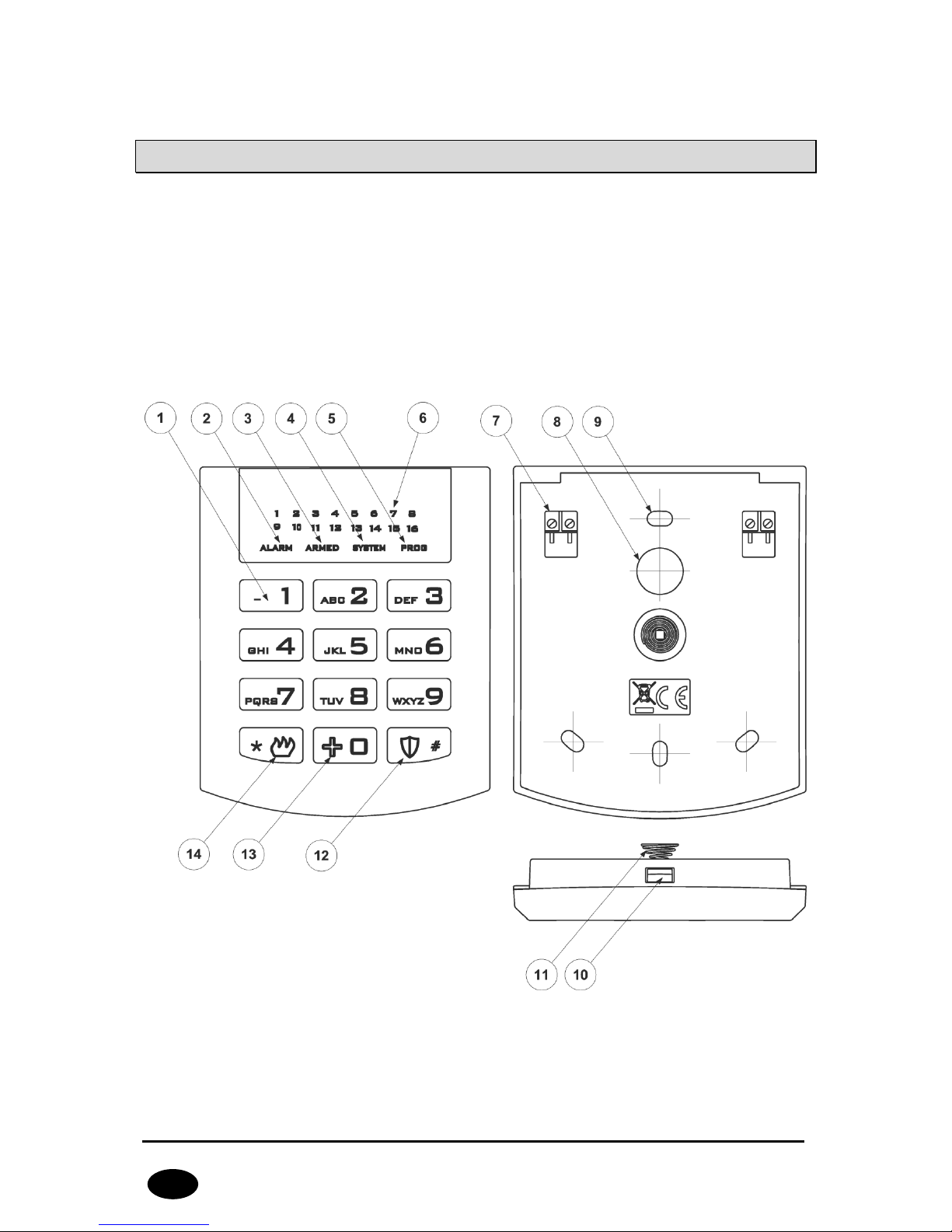
Drawing 1. KP16 Keypad
Page 8

CPX200NB ALARM CONTROL UNIT – USER MANUAL 8 / 30
EN
1. Keypad buttons
0-9 buttons and * as well as # are intended for the keypad and alarm control
unit operation. After first pressing any button, the keypad is backlit. After a fewsecond idle time, backlight gets automatically dimmed. In order to make codes
easier to remember, buttons are marked with the alphabet.
2. ALARM LED (red):
Flashing light – means that alarms occurred in the system (alarms memory).
Constant light – means that system is in alarm state.
Off – system is operating correctly.
3. ARMED LED (red):
Flashing light – means that time for leaving any of the partitions is counted.
Constant light – at least one partition is armed
Off – partitions disarmed.
4. SYSTEM LED (yellow):
Flashing light – means that in the control unit’s memory there are faults that has
already ceased (there was power loss, but it has already restored).
Constant light – there is a fault in the system that was not removed.
Off – no fault in the system.
5. PROG LED (blue):
Flashing slowly – service function is activated and it is one of the user functions.
Flashing – data will be entered.
Constant light – installer service function is activated.
6. 1 – 16 LEDs (red)
When LED goes on during normal operation, it means the line it is assigned to
was disrupted. Flashing LED means the zone was interlocked. After activating
service functions, LEDs display data.
7. Screwed Connectors
Connectors for connecting cables joining the keypad with the alarm control unit.
8. Cable Entry
It is a place for entering the connection cables.
9. Assembly Holes
The keypad was equipped with four round assembly holes for proper fastening
the keypad.
Page 9

CPX200NB ALARM CONTROL UNIT – USER MANUAL 9 / 30
EN
10. Casing Opening Latch
To open the casing it is recommended to use flat 2.5-5mm screwdriver. Insert it
slightly in indicated hole and perform slight lever movement toward the rear side
of the casing.
11. Anti-Sabotage Switch
After the keypad is assembled the switch contact is closed. Unauthorized
disassembly of the keypad will send the message to the alarm control unit. In
order to eliminate surface unevenness, a spring is located on the switch lever.
Page 10

CPX200NB ALARM CONTROL UNIT – USER MANUAL 10 / 30
EN
4. ARMING THE SYSTEM
4.1. ARMING MODES
Each partition can be armed in one of the following modes:
Stay (perimeter) – partition is armed, but only perimeter and perimeter
exit zones violation will cause an alarm,
Away (full) – partition is armed and violation of any zone will cause an
alarm.
User can choose the arming mode or let the system do it for himself.
4.2. ARMING THE SYSTEM
Stay mode is in fact a part of the Away mode. Every time a correct code is
given, the system will immediately arm in the stay mode (provided it has
perimeter zones). Afterwards, the system can automatically arm in the away
mode, if proper conditions were met.
4.2.1. Stay mode
Arming the partition in stay mode is possibile only if it has perimeter zones
assigned to it.
Partition will arm in the stay mode in following cases:
1. Input the user code, press and hold the button for 3 seconds
1
.
2. Input the user cold and press the button. If the perimeter exit zones
is violated during the exit time countdown, partition will arm in away
mode. If perimeter zone is not violated during the exit time countdown,
partition will remain armed in the stay mode.
1
Works only with KP16 keypad
Note: If incorrect code is entered the keypad will emit long
constant sound. Repeat the arming process by entering the
correct code.
Note: If the partition is not plugged any zones and/or outputs,
the partition is not armed.
Page 11

CPX200NB ALARM CONTROL UNIT – USER MANUAL 11 / 30
EN
4.2.2. Away mode
In order to arm the partition in the away mode, user has to input his code and
press the button. Exit time countdown will start. Partition will arm in the
stay mode in the following cases:
1. Partition has perimeter exit zones and at least one of them is violated
during the exit time countdown.
2. Partition does not have any perimeter exit zones.
Correct code will be confirmed by the keypad by 3 beeps.
Leave the facility before the time for leaving expires. That state is indicated by
intermittent sound and quick flashing the ARMED LED on the keypad until the
system gets fully armed. If the chirps are activated the arming will be
confirmed by one chirp of siren.
4.3. ARMING THE SYSTEM WITH FAULT
If during the arming any faults are present in the system, the keypad will indicate it
with flashing ARMED and SYSTEM LEDs and long constant audio signal. LEDs 1 to 8
will indicate which system errors are present. That state will maintain for 10 seconds.
If there is no possibility to quickly remove faults, press to arm the system.
Pressing will cancel the arming process.
Note: Remove the causes of faults as soon as possible.
Error codes:
1 – Damage or disruption of detector
2 – Damage of signalling device or signalling device active
3 – Damage of internal connection or sabotage
4 – AC power supply damage
5 – Battery damage
6 – ATS damage
8 – Other damages
Page 12

CPX200NB ALARM CONTROL UNIT – USER MANUAL 12 / 30
EN
5. DISARMING THE SYSTEM
5.1. DISARMING THE SYSTEM
1. Enter the facility through the entrance door. Intermittent sound and slow
flashing of ARMED LED on the keypad will remind of the need to disarm the
system before the delay time for entrance expires.
2. Enter the code and press . 3-tone beep of the keypad will confirm the
correct code input. The partition the user has access to will be disarmed. If
the chirps are activated the disarming will be confirmed by two chirps of siren.
If the user has access to all partitions, all of them will be disarmed. If there is
no armed partitions in the system, ARMED LED will be deactivated.
3. The system can be also disarmed in different way- by changing the partition
state. See item 6. PARTITION HANDLING.
4. When system is disarmed, alarm will be muted (deactivated).
Note: Incorrect code will be indicated with a long constant
sound. Enter the correct code immediately and press .
5.2. ALARM DISPLAY
If red ALARM LED flashes when the system is armed, it means that while you were
absent some alarms occurred (numbers of lines that initiated them will be displayed
as well) which have already ceased. But, if ALARM LED emits constant light, it means
that system still is in alarm state. Exercise caution! If you suspect any intruder to be
present in the facility, leave the facility immediately and call security guards.
5.3. ALARM MUTE
1. To mute (deactivate) the alarm, enter the code and press . 3 beeps will
confirm the code. Also, the system will be disarmed.
2. In order to identify the alarm type, please refer to ALARMS MEMORY chapter
of the present manual.
Page 13

CPX200NB ALARM CONTROL UNIT – USER MANUAL 13 / 30
EN
6. PARTITION HANDLING
6.1. ARMING / DISARMING WITH SELECTING PARTITIONS
1. Enter the number of the function and confirm using . Then enter
the user code and press . 3-tone beep will confirm the correct code
input.
Note: If incorrect code is entered the keypad will emit long
constant sound. Enter the correct code once again.
2. LEDs 1 and 2 will display the current partition state. LED on – partition armed,
LED off - partition disarmed. Only LEDs indicating the partitions the user has
access to will be on.
3. To change the partition state press buttons with partition numbers (LEDs with
relevant partition number will go on/off). Press to arm selected
partitions in the away mode. Pressing and holding the will arm the
selected partitions in the stay mode. 3 beeps will confirm the change. To
cancel the entered changes, press .
4. If partition arming in the away/auto mode was selected, the keypad will
indicate counting the time for leaving the facility. Leave the facility before the
time for leaving expires. After it is armed the ARMED LED will be constantly
on.
5. If the partition arming in the stay mode was selected, system will arm
immidiately. ARMED LED will turn on.
6. If partition disarming is selected, the relevant partition will be immediately
disarmed.
6.2. QUICK ARMING / DISARMING PARTITIONS
1. Enter the number of the function ( for partition one or
for partition two) and confirm using . Then enter the user code and press
to arm in the away/auto mode. To arm in the stay mode, press and hold
the button. 3-tone beep will confirm the correct code input.
Note: If incorrect code is entered the keypad will emit long
constant sound. Enter the correct code once again.
2. If partition arming in the away/auto mode was selected, the keypad will
indicate counting the time for leaving the facility. Leave the facility before the
Page 14

CPX200NB ALARM CONTROL UNIT – USER MANUAL 14 / 30
EN
time for leaving expires. After it is armed the ARMED LED will be constantly
on.
3. If the partition arming in the stay mode was selected, system will arm
immidiately. ARMED LED will turn on.
4. If partition disarming is selected, the relevant partition will be immediately
disarmed.
Page 15

CPX200NB ALARM CONTROL UNIT – USER MANUAL 15 / 30
EN
7. USER FUNCTIONS
7.1. ALARMS MEMORY
- Display of alarms memory
The function displays the history of alarms that occurred in the system. When the
function is activated, ALARM and PROG LEDs are flashing slowly and all alarms that
occurred since last arming are displayed. LEDs 1 – 7 display the information from
which zones the alarm was activated. To clear the alarms memory, press . To
exit without clearing the alarms memory, press .
Alarm source types:
Diodes 1 to 7 – Sabotage of lines 1 to 7
If no diodes are on and the ALARM led is blinking, then there alarms that were
triggered by the source other than input lines.
Other alarms
history can be accessed
by selecting following code from the main menu: .
After pressing the button corresponding to active LED, the detailed information about
the alarm source within selected type is displayed.
Pressing will result in return to the main menu.
Other alarm source types:
2 – Keypads tamper
3 – Emergency button used
Other alarm source types -> Keypads tamper:
1 – Keypad tamper 1
2 – Keypad tamper 2
3 – Keypad tamper 3
Other alarm source types -> Emergency button used:
1 – Fire alarm activated
2 – Help alarm activated
Note: Alarms memory is cleared after the system is armed.
Page 16

CPX200NB ALARM CONTROL UNIT – USER MANUAL 16 / 30
EN
7.2. FAULTS MEMORY
- Display of faults memory
The function displays the faults that are present in the system. When the function is
activated, SYSTEM and PROG LEDs are flashing slowly and all faults that are
currently present in the system are displayed. Led 1 – 8 display information on the
cause of fault. To clear the faults memory, press . To exit without clearing the
faults memory, press .
Faults description:
1 –
Sabotage of zones
To display more detailed information about sabotage of zones, press
button.
1 – Sabotage of zone 1
2 – Sabotage of zone 2
7 – Sabotage of zone 7
To return to the main fault menu, press .
2 –
Fault of outputs 1 - 3
To display more detailed information about fault of outputs, press
button.
1 – Fault of output 1
2 – Fault of output 2
3 – Fault of output 3
To return to the main fault menu, press .
3 –
Fault of feeding outputs
To display more detailed information about fault of feeding outputs, press
button.
1 – Fault of feeding output + KP
2 – Fault of feeding output +AUX1
3 – Fault of feeding output +AUX2
To return to the main fault menu, press .
4 –
AC fault
No more detailed information.
5 –
Battery fault
No more detailed information.
6 –
ATS fault
No more detailed information.
Page 17

CPX200NB ALARM CONTROL UNIT – USER MANUAL 17 / 30
EN
7 – Other damages
To display more detailed information about other damages, press
button.
1 – Clock fault
2 – Fault of central unit settings
3 –
Keypads tamper
To display more detailed information about keypads tamper, press
button.
1 – Keypad tamper 1
2 – Keypad tamper 2
3 – Keypad tamper 3
To return to the
Other damages
, press button.
To return to the main fault menu, press .
7.3. ZONE BLOCKING
The zone blocking function allows de-activating stand-by mode of any zones or
bypassing any damaged lines. Also, zones which are not in stand-by mode and which
the user has access to can be blocked. Zones remain blocked until de-arming.
System informs the user about that fact with quickly flashing LED marked with the
number of the blocked zone.
Zone blocking:
1. Enter the number of the function and confirm with . Enter the
user code and press . 3-tone beep will confirm the correct code input.
Note: If incorrect code is entered the keyboard will emit long
constant sound. Enter the correct code once again.
2. Use buttons numbered 1 to 7 to select zones you want to block.
3. Change the zones blocking status by pressing numbered buttons (LEDs with
relevant zone number will go on/off). Press to confirm blocking of
selected zones. 3 beeps will confirm the change. To cancel the entered
changes, press .
7.4. ADDING A NEW USER
You can add a new user code here. New codes can be added by the administrator
only. 3 beeps will confirm the successfully entered function. Default admin code:
1111.
Note: Individual code cannot be the same; if any code is the
same as another one, it will not be recorded.
Page 18

CPX200NB ALARM CONTROL UNIT – USER MANUAL 18 / 30
EN
To add a new user:
1. Enter the function code and press to confirm.
2. Enter the admin code and confirm it with . 3 beeps will confirm the
correct code input.
3. Numbers of already existing users will be displayed.
4. Enter the ID of newly added user (1 to 8), other than already added ID
numbers, and press to confirm. Numbers of partitions a new user can
have access to will be displayed.
5. To activate/deactivate LED of an appropriate partition, press 1 or 2. When the
access is set, press to confirm. All LEDs shall be off now.
6. Enter the code of a newly added user (4 to 7 digits) and press to
confirm.
7. Enter the code of a newly added user again and press to finish adding
or to exit without saving changes.
8. Successful adding a new user will be confirmed with 3 beeps, otherwise a
constant sound will be emitted.
7.5. USER DELETE
You can delete a user here. Codes can be deleted by the administrator only. 3 beeps
will confirm the successfully entered function. Default admin code: 1111.
Note: You cannot delete Admin account (user no. 0) and
Installer account (user no. 9)
To delete a user:
1. Enter the function code and press to confirm.
2. Enter the admin code and confirm it with . 3 beeps will confirm the
correct code input.
3. Numbers of already existing users will be displayed.
4. Enter the ID code (1- 8) of a user to be deleted and press to confirm or
to exit without saving changes.
5. Successful deletion of a user will be confirmed with 3 beeps, otherwise a
constant sound will be emitted.
7.6. CHANGE OF USER CODE
The user can change its code here. 3 beeps will confirm the successfully entered
function.
Page 19

CPX200NB ALARM CONTROL UNIT – USER MANUAL 19 / 30
EN
<User code > <Code> <Code>
where:
User code –
Code of a user changing the password
Code –
New access code (from 4 to 7 digits)
In any moment you can press to exit without saving changes.
7.7. PROGRAMMING TIME
You can change system time here. Time can be changed by the administrator only.
3 beeps will confirm the successfully entered function. Default admin code: 1111.
< Administrator code > <hh> <mm>
where:
Administrator code
– Administrator code.
hh
– Hours.
mm
– Minutes.
In any moment you can press to exit without saving changes.
7.8. PROGRAMMING DATE
You can change system date here. Date can be changed by the administrator only.
3 beeps will confirm the successfully entered function. Default admin code: 1111.
< Administrator code > <YY> <MM> DD>
where:
Administrator code
– Administrator Code.
YY
– Year.
MM
– Month.
DD
– Day.
In any moment you can press to exit without saving changes.
7.9. TESTING THE ZONES
The function allow user to test zones and detectors connected to zones input.
<User code> <Duration of test>
Page 20

CPX200NB ALARM CONTROL UNIT – USER MANUAL 20 / 30
EN
Duration of test
is the time in seconds after which the test will be finished and the
system will return to the main menu.
After activation this function, LEDs 1 – 7 display the zones used in the system. Only
zones belong to the user’s partitions are presented. Relevant LED goes off after
violation of the zone. Example of use: walk around the protected object and activate
detectors. After activate detectors, relevant LEDs will go off. LEDs that are still on,
indicate inactive or broken detectors.
To exit the testing function press or .
7.10. TESTING THE OUTPUTS
The function allow user to test outputs and alarm siren connected to the outputs.
< User code >
After activation this function, LEDs 1 – 3 display the outputs used in the system. Only
outputs defined as “alarm” type and belong to the user’s partitions are presented.
Pressing the key (1-3) activates relevant output (like an alarm), but not reporting the
event to the monitoring station. Thus the siren or other signalling devices can be
checked. Repeated pressing the key, disables the output.
To exit the testing function press or .
7.11. DURESS CODE
Duress code is used to inform the monitoring station about a distress event. Each
user has his own duress code. User’s duress code is his standard code with last digit
increased by one. If the last digit is 9 it should be changed to 0. Example:
User’s code is 3446, his duress code is 3447.
User’s code is 3449, his duress code is 3440.
Whenever duress code is input and confirmed by button, distress event will be
sent. It can be used in every command that requires user authorization, i.e.
arming/disarming and every system option that requires user code, like partition
state checking.
Duress code is disabled by default. It can be enabled by the installer or by the
configuration program.
7.12. EMERGENCY BUTTONS
The keypad of CPX200NB has 3 function keys. Pressing and holding for 3 seconds
one of these keys will generate an alarm2 corresponding to the key:
– Fire alarm
2
Works only with KP16 keypad
Page 21

CPX200NB ALARM CONTROL UNIT – USER MANUAL 21 / 30
EN
– Medical alarm
– Burglary alarm
Note – for the emergency buttons to work, it is necessary to be in arm/disarm ready
mode and wait at least 10 seconds since last 0-9 key press. You can also press ‘*’
key to clear keypad buffer and use emergency button after that without any delay.
Fire alarm – when activated it is signaled on a keypad with all digits blinking slow.
Enter and confirm any user code to deactivate it.
Medical alarm – when activated it is signal on a keypad with the ALARM led
blinking.
Panic alarm – not signaled on a keypad.
Every emergency alarm generates an event that can be send to the monitoring
station. Events configuration is set by the installer.
7.13. TEXT MESSAGES
CPX200NB Alarm Control Unit can be managed by text messages. User can use a
variety of texts that can be send to the device in order to configure it or poll its
status. For SMS to be accepted, the phone number from which the text is being
send, has to be enlisted on the allowed numbers list. CPX200NB can store up to 10
phone numbers and up to 32 text messages. If, for any reason, the SMS can not be
send at the moment, it will be send as soon as the connection with the GSM network
is re-established but not later than 1 day after the occurrence of the event triggering
SMS send request (text messages get expired and are deleted). Message should
contain only characters from English alphabet. Furthermore, if the text contains any
spaces, content of the message, starting from the equation mark ( = ) till the end of
the message, should be enclosed in quotes (" ").
Descriptions of messages handled by the unit are listed below:
Acquiring the state of partitions
Command syntax
XXXX GETARMED
Command description
Acquiring the information which partitions are
armed/disarmed
XXXX – user code
Example: 1234 GETARMED
Feedback message
PARTITION1:X, PARTITION2:Y
or
GETARMED:ERROR
Page 22

CPX200NB ALARM CONTROL UNIT – USER MANUAL 22 / 30
EN
Feedback message
description
PARTITION1:X, PARTITION2:Y - Information about
partitions arm/disarm state.
PARTITION1,PARTITION2 – default partitions names,
they can be changed with the SETNAME command
X,Y – partition states, possibile values:
0 – disarmed
1 – armed
GETARMED:ERROR – command rejected by the
system
Setting the name of partition
Command syntax
XXXX SETNAME=PARTITION,NR,VALUE
Command description
Setting the name of the partition.
XXXX – user code
NR – number of the partition, possibile values: 1 or 2
VALUE – new name of the partition
Example 1:
1234 SETNAME=PARTITION,1,Cellar
Example 2:
1234 SETNAME="PARTITION,2,Kids Room"
Feedback message
SETNAME::OK or SETNAME:ERROR
Feedback message
description
SETNAME::OK – command accepted
SETNAME:ERROR – command rejected by the system
Page 23

CPX200NB ALARM CONTROL UNIT – USER MANUAL 23 / 30
EN
Getting the name of partition
Command syntax
XXXX GETNAME=PARTITION,NR
Command description
Acquiring the name of the partition
XXXX – user code
NR – number of the partition, possibile values: 1 or 2
Example: 1234 GETNAME=PARTITION,1
Feedback message
GETNAME=PARTITION,NR,VALUE
or
GETNAME:ERROR
Feedback message
description
GETNAME=PARTITION,NR,VALUE – partition name
GETNAME:ERROR – command rejected by the system
Setting the phone number
Command syntax
XXXX SETTELNUM=ID,NUMBER
Command description
Setting the phone number for pointed index on the
phone number list
XXXX – user code
ID – index of phone number on the list, possible
values: 1 to 10
NUMBER – phone number, on which the texts will be
send
Example: 1234 SETTELNUM=3,800123456
Feedback message
SETTELNUM:OK
or
SETTELNUM:ERROR
Feedback message
description
SETTELNUM:OK – command accepted
SETTELNUM:ERROR – command rejected by the
system
Page 24

CPX200NB ALARM CONTROL UNIT – USER MANUAL 24 / 30
EN
Getting the phone number
Command syntax
XXXX GETTELNUM=ID
Command description
Getting the phone number for pointed index on the
phone number list
XXXX – user code
ID – index of phone number on the list, possible
values: 1 to 10
Example: 1234 GETTELNUM=2
Feedback message
GETTELNUM=ID,NUMBER
or
GETTELNUM:ERROR
Feedback message
description
GETTELNUM=ID,NUMBER – information about phone
number
GETTELNUM:ERROR – command rejected by the
system
Setting the content of text message
Command syntax
XXXX SETMESSAGE=ID,MESSAGE
Command description
Setting the content of text message under the
pointed index
XXXX – user code
ID – index of text, possible values: 1 to 32
MESSAGE – content of the text message
Example: 1234 SETMESSAGE=4,Robbery
Feedback message
SETMESSAGE:OK or SETMESSAGE:ERROR
Feedback message
description
SETMESSAGE:OK – command accepted
SETMESSAGE:ERROR – command rejected by the
system
Page 25

CPX200NB ALARM CONTROL UNIT – USER MANUAL 25 / 30
EN
Getting the content of text message
Command syntax
XXXX GETMESSAGE=ID
Command description
Getting the content of text message under the
pointed index
XXXX – user code
ID – index of text, possible values: 1 to 32
Example: 1234 GETMESSAGE=30
Feedback message
GETMESSAGE=ID,MESSAGE
or
GETMESSAGE:ERROR
Feedback message
description
GETMESSAGE=ID,MESSAGE – information about the
contents of text message
GETMESSAGE:ERROR – command rejected by the
system
Page 26

CPX200NB ALARM CONTROL UNIT – USER MANUAL 26 / 30
EN
Assigning a text message and a phone number to the event
Command syntax
XXXX SETUSERSMS=EVENT,TELNUM,MSG_ID
Command description
Assigning a text message and a phone number to the
event. The text will be send to the phone number
when this event occurs.
XXXX – user code
EVENT – a short name of the event, possible event
names are listed at the end of this chapter
TELNUM – ten-digit chain of zeroes and ones. Each
digit (counting from the left) represents an index of
the phone number – first digit for the first phone
number, second digit for the second number, and so
on.
0 – message will not be send to this number
1 – message will be send to this number
Example:
1234 SETUSERSMS=ARM1,1000000110,6
Means, that when ARM1 event occurs (partition 1
armed), text message number 6 will be sent to phone
numbers with indexes 1,8 and 9.
Feedback message
SETUSERSMS=EVENT,TELNUM,MSG_ID:OK
or
SETUSERSMS=EVENT,TELNUM,MSG_ID:ERROR
Feedback message
description
SETUSERSMS=EVENT,TELNUM,MSG_ID:OK –
command accepted
SETUSERSMS=EVENT,TELNUM,MSG_ID:ERROR –
command rejected by the system
Page 27

CPX200NB ALARM CONTROL UNIT – USER MANUAL 27 / 30
EN
Getting a text message content and a phone number assigned to the
event
Command syntax
XXXX GETUSERSMS=EVENT
Command description
Getting the content of a text message and a phone
number assigned to the specified event.
XXXX – user code
EVENT – a short name of the event, possible event
names are listed at the end of this chapter
Example:
1234 GETUSERSMS=ARM1
Feedback message
GETUSERSMS=EVENT:TELNUM,MSG_ID
or
GETUSERSMS=EVENT:ERROR
Feedback message
description
GETUSERSMS=EVENT:TELNUM,MSG_ID –
information about text message and phone number
assinged to the event
GETUSERSMS=EVENT:ERROR – command rejected
by the system
Page 28

CPX200NB ALARM CONTROL UNIT – USER MANUAL 28 / 30
EN
List of events handled by the SETUSERSMS and GETUSERSMS commands
Alias name
Description
ARM1
Partition 1 armed
ARMSTAY1
Partition 1 armed in perimeter mode
ARM2
Partition 2 armed
ARMSTAY2
Partition 2 armed in perimeter mode
DISARM1
Partition 1 disarmed
DISARM2
Partition 2 disarmed
INPUT1
(to INPUT7)
Violation of zones 1…7
INPUT1-OFF
(to INPUT7-OFF)
Violation of zones 1…7 ended
INPUT1-TAMPER
(to INPUT7-TAMPER)
Sabotage of zones 1…7
INPUT1-TAMPEREND
(to INPUT7-TAMPEREND)
Sabotage of zones 1…7 ended
INPUT1-LOCK
(to INPUT7-LOCK)
Bypass of zones 1…7
INPUT1-UNLOCK
(to INPUT7-UNLOCK)
Bypass of zones 1…7 ended
OUTPUT1-ON
(to OUTPUT3-ON)
Zones 1…3 triggered
OUTPUT1-OFF
(to OUTPUT3-OFF)
Zones 1…3 trigger ended
OUTPUT1-TAMPER
(to OUTPUT3-TAMPER)
Fault of zones 1…3
OUTPUT1-TAMPEREND
(to OUTPUT3-TAMPEREND)
Fault of zones 1…3 ended
POWER-FAIL
Power failure
POWER-OK
Power failure ended
BATTERY-FAIL
Battery failure
Page 29

CPX200NB ALARM CONTROL UNIT – USER MANUAL 29 / 30
EN
BATTERY-OK
Battery failure ended
AUX1-FAIL
Failure of auxiliary output 1
AUX2-FAIL
Failure of auxiliary output 2
AUX1-OK
Failure of auxiliary output 1 ended
AUX2-OK
Failure of auxiliary output 2 ended
KEYPAD1-LOST
(to KEYPAD3-LOST)
Failure of keypad 1...3
KEYPAD1-OK
(to KEYPAD3-OK)
Failure of keypad 1...3 ended
KEYPAD1-TAMPER
(to KEYPAD3-TAMPER)
Sabotage of keypad 1…3
KEYPAD1-TAMPEREND
(to KEYPAD3-TAMPEREND)
Sabotage of keypad 1…3 ended
KEYPAD-FIRE-BEGIN
‘Fire’ alarm started
KEYPAD-HELP-BEGIN
‘Help’ alarm started
KEYPAD-SILENTALARM-
BEGIN
‘Panic’ alarm started
KEYPAD-FIRE-END
‘Fire’ alarm ended
JAMMING-BEGIN
GSM jamming
JAMMING-END
GSM jamming ended
List of errors sent as feedback messages
Alias name
Description
ERROR-PERMISSION
Permission to issue this command was not granted
ERROR-FORMAT
Wrong command syntax
ERROR-VALUE
Wrong parameter value
ERROR-EMPTY
Parameter value missing
ERROR
Other error
Page 30

CPX200NB ALARM CONTROL UNIT – USER MANUAL 30 / 30
EN
8. THE BEHAVIOR OF THE SYSTEM IN COMPATIBILITY
MODE FOR GRADE 2
The system operates in accordance with the EN 50131 standard requirements for
Grade 2, i.e.:
zones status is available only after user code has been entered
information about alarms is available only after user code has been entered
information about alarms memory is available only after user code has been
entered
information about failures is available only after user code has been entered
information about failures memory is available only after user code has been
entered
arming requires authorization
prior to arming, the control panel checks circumstances that may prevent
arming
the codes in the system must be at least 5 characters
after entering an invalid code three times, all keypads in the system will be
blocked for 90 seconds.
9. CHANGE HISTORY
Date / Version / Firmware
Description
22.09.2014 / i1.0 / 2.0RC6
First version of the manual
26.11.2014 / i1.1 / 2.0RC7
Small changes
18.06.2015 / i1.2 / 2.1.0
Added: duress code, stay/away, function keys
03.09.2015 / i1.3 / 2.2.0
Added new EVENT class parameters, which are used
by GETUSERSMS and SETUSERSMS commands
08.10.2015 / i1.4 / 2.2.0
Updated information about stay/away mode
09.11.2015 / i1.5 / 2.3.1
Updated information about stay/away mode
08.01.2016 / i1.6 / 2.3.7
Updated information about testing the outputs
 Loading...