

Page 1
Compact Diagonal
1
2
3
0.00
0.20
0.40
0.60
0.80
1.00
1.20
1.40
1.60
0 100 200 300 400 500 600
q cfm
p
fs
q cfm
p
fs
q cfm
p
fs
q cfm
p
fs
in. wg
5
6
7
4
8
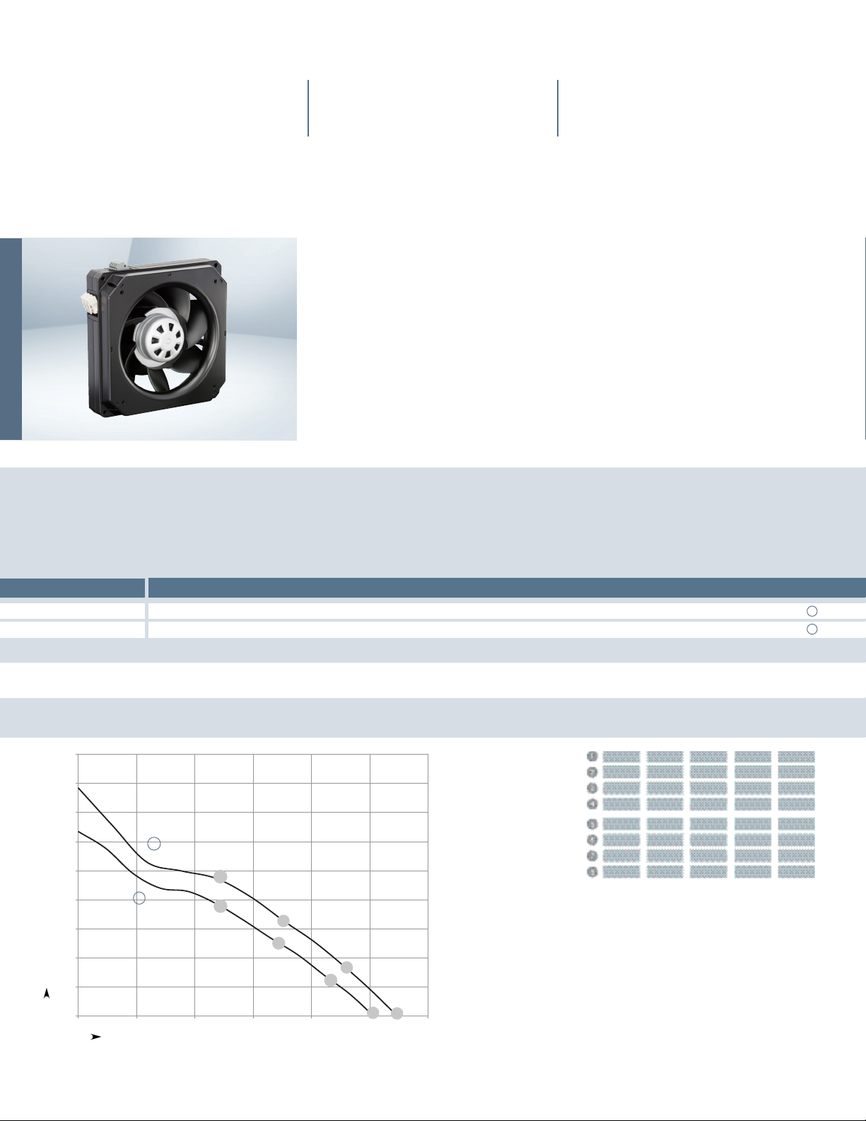
Series K3G200-AD Ø 200 mm
Highlights:
– Control Input: 0-10 VDC/PWM
– Output: 10 VDC, max 1.1 mA
– Tach Output
– Over-temperature protected electronics/motor
– Soft start, motor current limit
– Locked rotor protection
Material: Impeller: PA plastic
Housing: PP plastic
Mounting position: Any
Condensate discharge holes: None, open rotor
Direction of rotation: Clockwise, seen on rotor
(1)
(1)
(1)
(1)
Nominal Data
Type Motor cfm VAC VAC Hz W rpm A in. H20 °C lbs
K3G200-AD21-01 M3G055-BI 547 1
K3G200-AD11-02 M3G055-BI 506 1
(1) Nominal data at maximum load.
Air flow
Phase
~
230V 200...240 50/60 80 3100
~
115V 100...130 50/60 65 2850
Curves
A
B
Voltage
Voltage range
Frequency
Power input
Speed
Air performance measured as per:
ISO 5801, Installation category
A, without protection against
accidental contact.
Suction-side noise levels: LWA as
per ISO 13347, LPA measured at
1m distance to fan axis.
The values given are valid
under the measuring conditions
mentioned and may vary accoring
to the actual installation situation.
With any deviation to the standard
set-up, the specific values have
to be checked and reviewed once
installed or fitted.
For detailed information on the
measuring set-up, please contact
ebm-papst.
Current draw
0.7 0.884
1.0 0.723
Max back pressure
Temperature range
Mass
Bearing
-25...60 4.41 Ball IP54 Yes
-25...60 4.41 Ball IP54 Yes
n
Pe
rpm
3160 69 0.63 64 72
3120 75 0.68 62 70
3100 80 0.70 61 69
3100 76 0.69 61 69
2945 59 0.96 62 70
2885 62 1.00 61 69
2850 65 1.00 59 68
2845 64 1.00 59 68
W
I ALpAin
dB(A)
Ingress protection rating
UL
LwAin
dB(A)
Chart
A
B
Page 2
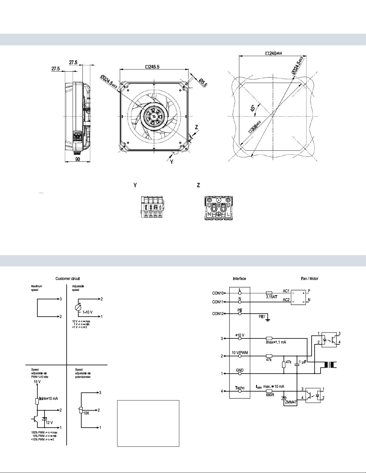
K3G200-ADXX-XX
Dimensions shown in millimeters
Connection screen
Conn. Designation Color Function/assignment
CON10 L black Power supply for voltage range refer to rating plate
CON11 N blue Neutral conductor
CON12 PE green/yellow Protective earth
1 GND blue GND-Connection for control interface
2 0- 10V PWM yellow Control input0-10Vor PWM, electrically isolated
3 10V/ max 1.1mA red Voltage output 10V/1.1 mA, electrically isolated
4 Tach white Tach output: open collector,1pulse per revolution, electrically isolated, Isink max=10 mA
 Loading...