

Ebmpapst CN1116 Operating And Maintenance Instructions Manual
Operating and Maintenance Instructions
210-OMI14229-Iss2
Operation & Maintenance Instructions
Page 1 of 45
© ebm-papst UK Ltd 2018
Chelmsford Business Park Chelmsford Essex CM2 5EZ
Telephone: +44(0)1245468555 Fax: +44(0)1245466336
e-mail sales@uk.ebmpapst.com
Part No
CN1116
Description
Modbus Display & Control (MDC)
Issue
Date
Author
Comments
2
11/12/2018
Felipe
Pagliarini
Second Release

Operating and Maintenance Instructions
210-OMI14229-Iss2
Operation & Maintenance Instructions
Page 2 of 45
© ebm-papst UK Ltd 2018
Chelmsford Business Park Chelmsford Essex CM2 5EZ
Telephone: +44(0)1245468555 Fax: +44(0)1245466336
e-mail sales@uk.ebmpapst.com
Table of Contents
1.0 Safety Notice .............................................................................................................................................. 5
2.0 Introduction ................................................................................................................................................. 6
3.0 Overview .................................................................................................................................................... 7
3.1 Specification .................................................................................................................................................. 7
3.2 Installation ..................................................................................................................................................... 7
3.3 Hot plugging .................................................................................................................................................. 7
3.4 RS485 wiring installation ............................................................................................................................... 7
4.0 Configuration and first use of the MDC.............................................................................................................. 8
4.1 Electrical connection – general information ................................................................................................... 8
4.2 General and Initial Power ON ....................................................................................................................... 8
4.3 Configuring the Fan Array ............................................................................................................................. 9
4.3.1 Configuring the MDC with fans that are in their factory default setting .................................................. 9
4.3.2 Auto addressing fans using the fan’s serial numbers .......................................................................... 10
4.3.3 Configuring the MDC with fans that have been pre-configured ........................................................... 10
4.4 Fan Status screen ....................................................................................................................................... 11
4.5 Power Meter screen .................................................................................................................................... 12
4.6 Changing the fan addressing order ............................................................................................................. 12
5.0 Operating Modes ...................................................................................................................................... 13
5.1 General ....................................................................................................................................................... 13
5.2 Accessing the main menu ........................................................................................................................... 13
5.3 Monitor mode (default operation) ................................................................................................................ 13
5.3.1 Monitor mode: single fan connection ................................................................................................... 14
5.3.2 Monitor mode: multiple fan connection ................................................................................................ 14
5.3.3 Monitor mode: pressure sensor connection – differential pressure or volume measurement .............. 15
5.4 Monitor & Control mode .............................................................................................................................. 15
5.4.1 General ................................................................................................................................................ 15
5.4.1.2 Measuring the fan performance using a pressure sensor ................................................................. 15
5.4.1.3 Control options in Monitor & Control mode ....................................................................................... 16
5.4.2.1 0-10V Input control option using a potentiometer and 10VDC supply from the fans......................... 16
5.4.2.2 0-10V Input control option using potentiometer and the on-board 10VDC supply ............................ 17
5.4.2.2 0-10V Input control option using an external 0-10V supply............................................................... 17
5.4.3 Modbus control option ......................................................................................................................... 17
5.4.4 Keypad control option .......................................................................................................................... 18
5.4.5 Differential pressure or volume flow measurement when using Modbus and/or Keypad control options
...................................................................................................................................................................... 18
5.5 Constant Volume/Constant Pressure operating mode ................................................................................ 19
5.5.1 General ................................................................................................................................................ 19
5.5.2 Constant volume/constant pressure mode .......................................................................................... 19
5.6 Modbus relay operating mode ..................................................................................................................... 20

Operating and Maintenance Instructions
210-OMI14229-Iss2
Operation & Maintenance Instructions
Page 3 of 45
© ebm-papst UK Ltd 2018
Chelmsford Business Park Chelmsford Essex CM2 5EZ
Telephone: +44(0)1245468555 Fax: +44(0)1245466336
e-mail sales@uk.ebmpapst.com
5.7 Advanced Settings Submenu ...................................................................................................................... 21
5.8 Fan replacement ......................................................................................................................................... 23
6.0 Fault Indication ......................................................................................................................................... 23
6.1 Loss of communication and fan alarms ....................................................................................................... 23
6.2 Warning indications ..................................................................................................................................... 24
7.0 Replacing a MDC unit .............................................................................................................................. 24
8.0 Transport & Storage ................................................................................................................................. 24
9.0 Maintenance and servicing ....................................................................................................................... 24
10.0 Copy of CE certificate front sheet ............................................................................................................. 25
Appendix A – Physical Details ............................................................................................................................... 26
Appendix B – Electrical Connections ..................................................................................................................... 27
Appendix C – Remote Monitoring & Control .......................................................................................................... 28
C.1 Remote Monitoring ..................................................................................................................................... 28
C.2 Remote Fan Array Control .......................................................................................................................... 28
C.3 Remote Single Fan Speed Control ............................................................................................................. 28
Appendix D – Modbus Input Registers .................................................................................................................. 29
Appendix E – Modbus Holding Registers .............................................................................................................. 30
Appendix F – Alarms and Warnings Holding Registers Breakdown ...................................................................... 36
Appendix G – Example of Modbus Relay Operation ............................................................................................. 37
Appendix H – Menu Structure Flow Chart ............................................................................................................. 38
H1 – Fan Addressing - New Fan Array -Initial Setup ........................................................................................ 38
H2 – Fan Addressing - Existing Fan Array - Initial Setup .................................................................................. 38
H3 – Initial Factory Reset .................................................................................................................................. 38
H4 – Fan Replacement ..................................................................................................................................... 38
H5 – Main Menu ................................................................................................................................................ 38
H6 – Status ....................................................................................................................................................... 39
H7 – Operation Mode – Monitor ........................................................................................................................ 39
H8 – Operation Mode - Monitor & Control ......................................................................................................... 40
H9 – Operation Mode - Constant Volume / Constant Pressure ........................................................................ 40
H10 – Operation Mode - Modbus Relay ............................................................................................................ 40
H11 – Keypad Control ....................................................................................................................................... 40
H12 – Operation Mode - Constant Volume / Constant Pressure Details........................................................... 41
H13 – Advanced Settings – RPM Limit ............................................................................................................. 41
H14 – Advanced Settings – 0-10V Control Cap ................................................................................................ 42
H15 – Advanced Settings – 0-10V Input Cap.................................................................................................... 42
H16 – Advanced Settings – Alarm Output (Sensor Disabled) ........................................................................... 42
H17 – Advanced Settings – Alarm Output (Sensor Enabled) ............................................................................ 42
H18 – Advanced Settings – BMS Settings ........................................................................................................ 43
H19 – Advanced Settings – Main Menu Lock ................................................................................................... 43
H20 – Advanced Settings – LCD Brightness..................................................................................................... 44
H21 – Advanced Settings – Factory Reset ....................................................................................................... 44
H22 – Advanced Settings – Measurement Unit ................................................................................................ 45

Operating and Maintenance Instructions
210-OMI14229-Iss2
Operation & Maintenance Instructions
Page 4 of 45
© ebm-papst UK Ltd 2018
Chelmsford Business Park Chelmsford Essex CM2 5EZ
Telephone: +44(0)1245468555 Fax: +44(0)1245466336
e-mail sales@uk.ebmpapst.com
H23 – Advanced Settings – PID Settings .......................................................................................................... 45
Table of Figures
Figure 1 - Schematic of RS485 installation.............................................................................................................. 7
Figure 2 – Typical wiring for default operating mode when used with multiple fans ................................................ 8
Figure 3 - Fan status screen showing that the MDC had a previously stored fan array .......................................... 8
Figure 4 - Keypad buttons ....................................................................................................................................... 9
Figure 5 - Main menu display screen on first application of power .......................................................................... 9
Figure 6 - Fan status screen .................................................................................................................................. 11
Figure 7 – Power meter screen ............................................................................................................................. 12
Figure 8 – Typical wiring diagram for Monitor operating mode - single fan monitoring ......................................... 14
Figure 9 - Typical wiring diagram for Monitor operating mode - multiple fan monitoring ....................................... 14
Figure 10 - Typical wiring diagram for Monitor operating mode – using external sensor monitoring ..................... 15
Figure 11 - Typical wiring diagram for Monitor & Control operating mode – potentiometer control signal and fan
10VDC supply........................................................................................................................................................ 16
Figure 12 - Typical wiring diagram for Monitor & Control operating mode – potentiometer control signal and on-
board 10VDC supply ............................................................................................................................................. 17
Figure 13 - Typical wiring diagram for Monitor & Control operating mode – external 0-10V control signal ........... 17
Figure 14 - Typical wiring diagram for Monitor & Control operating mode - Modbus RS485 control signal ........... 17
Figure 15 - Typical wiring diagram for Monitor & Control operating mode - keypad control signal ........................ 18
Figure 16 - Typical wiring diagram for Monitor & Control operating mode - using external sensor monitoring ...... 18
Figure 17 - Typical wiring diagram for Constant volume / Constant pressure operating mode ............................. 19
Figure 18 – MDCs operating as Modbus Relays connected to a BMS network and sub-network of fans ............. 20
Figure 19 - Communication Lost Figure 20 - Fan Alarm .............................................................................. 23
Figure 21 - Example of a first warning on a fan Figure 22 - Example of a second warning on a fan ................ 24
Figure 23 - PCB Connections ................................................................................................................................ 27
Table of Tables
Table 1 - Information shown on the MDC display for a single fan ........................................................................... 6
Table 2 - Information shown on the MDC display for the fan array ......................................................................... 6
Table 3 - Specification ............................................................................................................................................. 7
Table 4 – PCB Bottom Side Connector Identities and Pin Functions .................................................................... 27
Table 5 – PCB Top Side Connector and Pin Function .......................................................................................... 27
Table 6 - Modbus Input Registers ......................................................................................................................... 29
Table 7 – Controller’s Dedicated Modbus Holding Registers Part 1 ...................................................................... 30
Table 8 – Controller’s Dedicated Modbus Holding Registers Part 2 ...................................................................... 31
Table 9 – Direct Access to Individual Fan Holding Registers ................................................................................ 31
Table 10 – Alarms Registers Breakdown .............................................................................................................. 36
Table 11 – Warning Registers Breakdown ............................................................................................................ 36
• To assure proper usage, we ask you to read these operating instructions carefully before installation
and commissioning of the control device.
• To download these full operating and maintenance instructions please visit
www.ebmpapst.co.uk/instructions
• The CE documentation can be found on the full operating and maintenance instructions available from
the website.

Operating and Maintenance Instructions
210-OMI14229-Iss2
Operation & Maintenance Instructions
Page 5 of 45
© ebm-papst UK Ltd 2018
Chelmsford Business Park Chelmsford Essex CM2 5EZ
Telephone: +44(0)1245468555 Fax: +44(0)1245466336
e-mail sales@uk.ebmpapst.com
1.0 Safety Notice
CAUTION – Safety
• The Modbus Display & Control is only suitable for a safety extra low voltage supply of 10VDC up to 24VDC
CAUTION – Electro-Static Discharge
• Many modern electronic components are susceptible to damage from Electro-Static Discharge (Static
Electricity). During programming and commissioning, avoid unnecessary contact with electronic
components on PCB’s. PCB’s which are sensitive to static discharges and should be stored and
transported in anti-static packaging until they are required to be used.
Warning – Do not operate in an explosive atmosphere
Warning – The fans may start during connection and programming. If there is a residual risk of
contact with a fan then contact shall be prevented by suitable control methods to prevent accidental
contact

Operating and Maintenance Instructions
210-OMI14229-Iss2
Operation & Maintenance Instructions
Page 6 of 45
© ebm-papst UK Ltd 2018
Chelmsford Business Park Chelmsford Essex CM2 5EZ
Telephone: +44(0)1245468555 Fax: +44(0)1245466336
e-mail sales@uk.ebmpapst.com
2.0 Introduction
The Modbus Display & Control (MDC) is a device with two RS485 ports, a keypad for setting parameters and a
display to view the status of the connected equipment. One port, the master RS485, communicates with ebm-papst
Modbus enabled, electronically commutated fans with software version 5.0 or later using a two-wire plus ground
RS485 connection. The second port, the slave RS485, communicates with a higher level third-party system such
as a Building Management Systems (BMS), providing real-time monitoring and control data.
The master port can search, address, and talk to up to 100 fans connected to its network.
The MDC provides an auto-addressing facility to ease installation and commissioning, and supports four different
operating modes as explained below:
• Monitor operating mode
o Monitors pre-defined parameters and reports the information via the digital display and the RS485
slave port, see Tables 1 and 2 below
o A fault condition will be raised by an on-board LED and a volt-free relay
o An optional DS85 differential pressure sensor can provide a signal to display either differential
pressure or used by the MDC to calculate and display volume flow
• Monitor & Control operating mode
o As per Monitor operating mode plus the fan speed is controlled by one, or a combination of:
▪ 0-10V control signal input to the MDC
▪ Third-party Modbus master system connected to the RS485 slave port of the MDC
▪ Local control using the MDC keypad
o An optional DS85 pressure sensor can provide a signal to display either differential pressure or
used by the MDC to calculate and display volume flow
• Constant Volume / Constant Pressure Control operating mode
o As per Monitor operating mode but requires an external DS85 differential pressure sensor used
by the MDC to maintain a constant volume / constant pressure. The constant volume / constant
pressure setpoint can be entered via the keypad or via the RS485 slave port
• Modbus Relay operating mode
o The MDC stops getting information from the fans and/or setting the fan array speed and becomes
a messenger between the fans and a third-party Modbus master system thus allowing direct
access to all Modbus registers on each fan and individual speed control for each fan.
The MDC will display the following parameters from each connected fan (except during Modbus Relay operation):
Actual Speed (RPM)
Set Point (%)
Fan Serial Number
Motor Temperature (oC) *1
Electronics Temperature (oC)
Hours Run (h)
Fan Power Consumption (W)
Fan Warnings
Table 1 - Information shown on the MDC display for a single fan
The MDC will also display the following parameters from the fan array:
Total Power Consumption (kW)
Volume (m3/h or CFM) or
Pressure (Pa or INWG) *2
Table 2 - Information shown on the MDC display for the fan array
Note *1 - The controller is compatible with all firmware versions of ebm-papst enabled Modbus EC fans
version 5.0 and later, however, on ‘Modbus LITE’ reduced functionality fans, the parameter ‘Motor
Temperature’ will be displayed as “N/A”.
Note *2 - Volume and pressure (either metric or imperial) is only available using an external differential
pressure sensor type DS85, models 50 Pa up to 2000 Pa
Operating and Maintenance Instructions
210-OMI14229-Iss2
Operation & Maintenance Instructions
Page 7 of 45
© ebm-papst UK Ltd 2018
Chelmsford Business Park Chelmsford Essex CM2 5EZ
Telephone: +44(0)1245468555 Fax: +44(0)1245466336
e-mail sales@uk.ebmpapst.com
3.0 Overview
3.1 Specification
Product
Modbus Display & Control - CN1116
Supply Voltage
Two sets of connections are provided for either:
• 10 VDC to 24VDC from an optional external PSU or
• 10 VDC sourced from connection to the fan PSU*
(note that fan PSU must be the >10 mA version)
Reverse polarity protected
Supply Current
10mA (low LDC backlight) – 40mA (full LCD backlight)
Enclosure
CN1116 – wall mount
Enclosure Dimensions
See Appendix A – Physical Details
Weight
CN1116 – 204 g
Operating Environment
CN1116 is -20°C to +60°C, 90%RH at 40°C max.
EMC Compliance
BS EN61000-6-3 (emissions)
BS EN61000-6-2 (immunity)
* Patent GB 2 431 303
Table 3 - Specification
3.2 Installation
Avoid exposure to vibration, high temperatures. Control of exposure to water and dust varies with each design. The
unit shall be installed according to relevant safety guidelines and requirements. Attention should be paid to local
regulations and guidance.
3.3 Hot plugging
Hot plugging the MDC is permissible, however, if a new or replacement MDC is not at factory default settings, it will
need to be reset to such. Please see Section 7.0 Replacing a MDC unit for more details.
3.4 RS485 wiring installation
It is recommended to use shielded RS485 cable separated from mains supply wiring. For reliable system operation
the RS485 wiring should be installed in accordance with standard industry good practice. Use a “Daisy Chain” linear
cable layout avoiding “Star” layout or “Stubs”. We recommend the MDC to be at one end of the RS485 network. It
has a built-in 560Ω termination resistor on its RS485 Master Port and therefore another 560Ω termination resistor
should be added at the other end of the network cable as shown in Figure 1 below:
Figure 1 - Schematic of RS485 installation
In case the MDC is in the middle of the network, the built-in termination resistor must be taken out of the circuit by
removing the jumper bar located on the PCB. Please note that in this case, two resistors of the same value are
required at each end of the network.
560Ω
Operating and Maintenance Instructions
210-OMI14229-Iss2
Operation & Maintenance Instructions
Page 8 of 45
© ebm-papst UK Ltd 2018
Chelmsford Business Park Chelmsford Essex CM2 5EZ
Telephone: +44(0)1245468555 Fax: +44(0)1245466336
e-mail sales@uk.ebmpapst.com
4.0 Configuration and first use of the MDC
4.1 Electrical connection – general information
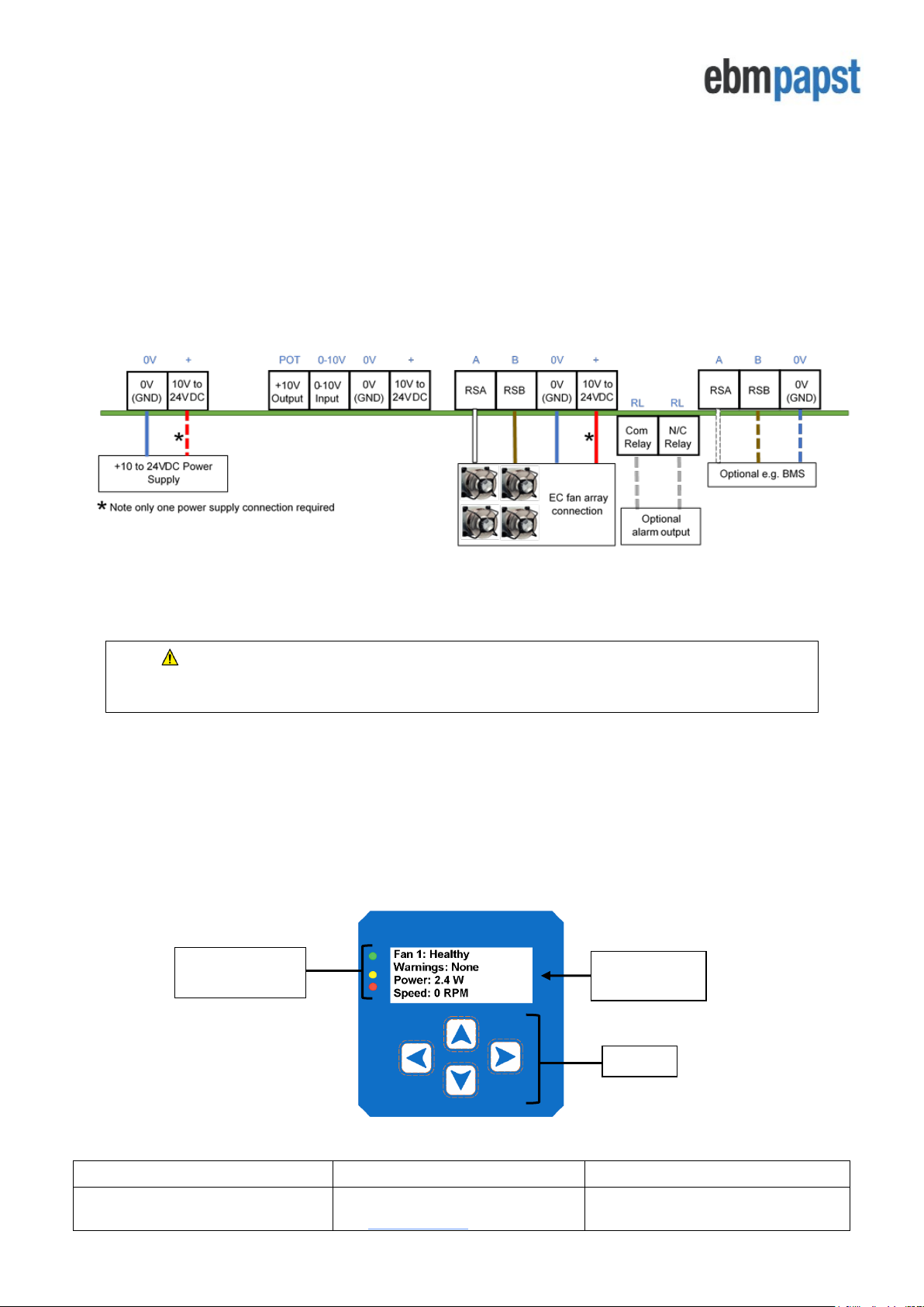
The electrical connections are shown in Appendix B – Electrical Connections. The required connections to the
MDC will depend on the intended use, i.e. the intended operating mode, and the desired configuration of fans,
sensors, inputs and outputs.
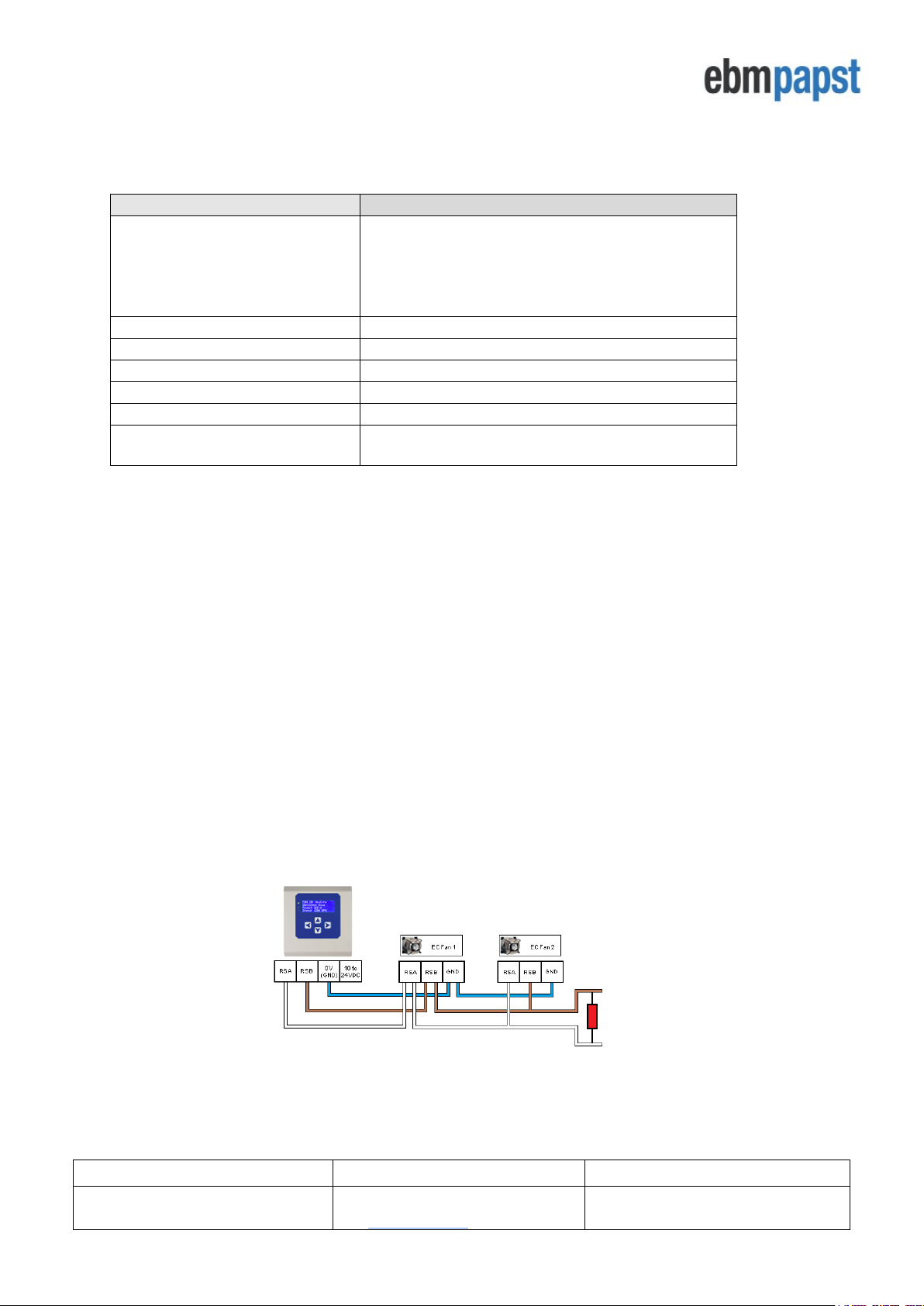
A suggested connection diagram for each operating mode is shown in Section 5.0 Operating Modes. For the
purpose of explaining the initial configuration and first use of the MDC, the connection diagram for the factory
default operating mode of “Monitor” is show in Figure 2 below:
Figure 2 – Typical wiring for default operating mode when used with multiple fans
CAUTION: Danger of damaging the fan if two power supplies are connected at the same time
Do not connect the fan’s 10Vdc output to the controller if powering the controller from an external supply
4.2 General and Initial Power ON
The MDC is pre-installed with four different operating modes, see Section 2.0 Introduction
When powered is applied, the MDC undertakes a PCB and software version check and then interrogates the onboard memory for a previously stored fan array and configuration parameters. If there is a previously stored fan
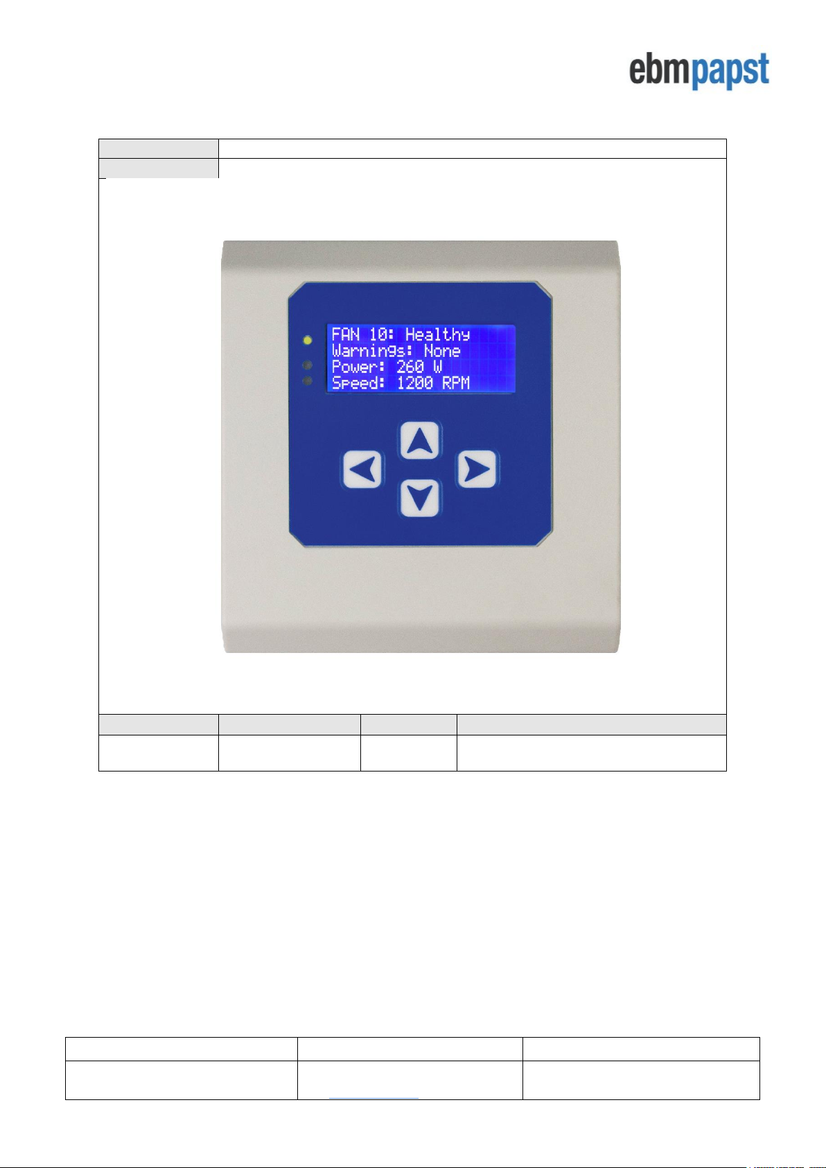
array, the MDC will display the status screen of the first fan in the array as shown in Figure 3 below. If there is no
previously stored fan array the MDC will display the Main Menu screen where setup is required, see Figure 5.
Figure 3 - Fan status screen showing that the MDC had a previously stored fan array
Text Display
Screen
Keypad
Status Indicator
LEDs
Operating and Maintenance Instructions
210-OMI14229-Iss2
Operation & Maintenance Instructions
Page 9 of 45
© ebm-papst UK Ltd 2018
Chelmsford Business Park Chelmsford Essex CM2 5EZ
Telephone: +44(0)1245468555 Fax: +44(0)1245466336
e-mail sales@uk.ebmpapst.com
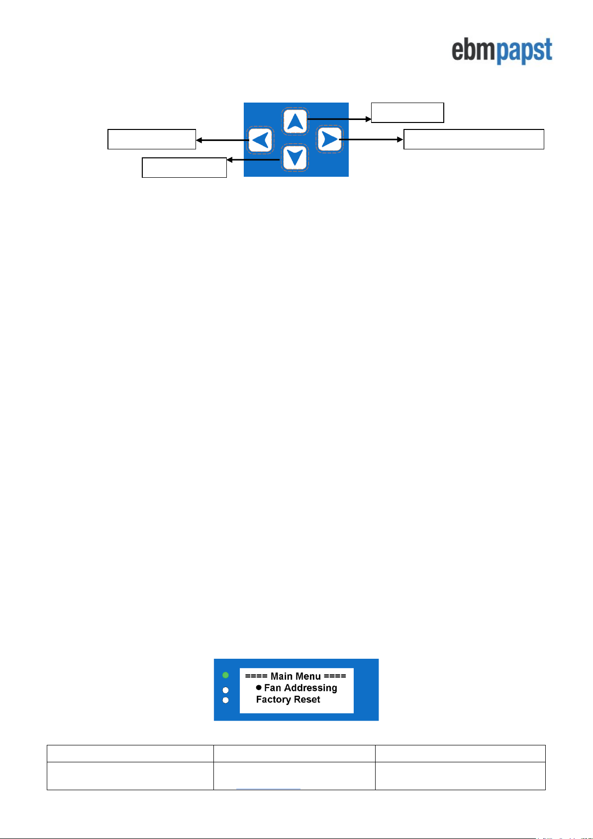
The MDC has three fan status indicator LEDs, a text screen and a keypad interface to navigate around the
configuration menus and fan information.
Figure 4 - Keypad buttons
• The FORWARD / ENTER button moves forward to the next fan if monitoring a fan’s status screen or
confirms the request / change of a set value if configuring parameters
• The UP and DOWN buttons navigate through the screens and change set values
• The BACK button moves back one step in the software structure without saving any changes made
Menu structures are shown with the use of flow charts in Appendix H – Menu Structure Flow Chart. There are
flow charts for various tasks, set up of each mode, settings, use of the MDC, interrogation of alarms, etc. For
example, H1 – Fan Addressing - New Fan Array -Initial Setup shows the menu structure for initial set up with
new fans, H2 – Fan Addressing - Existing Fan Array - Initial Setup shows the menu structure for initial set up
where the fans are already addressed and H20 – Advanced Settings – LCD Brightness shows how to change
illumination of the LCD.
Once configured and when in normal operating mode, the green fan status indicator LED will be on and the MDC
will display the operating condition of the fans. Using the keypad interface, the user can scroll through the network
of connected fans to check set points, power consumption, alarm conditions and fan warnings from each fan.
When a fan enters an alarm state or has lost communication, the MDC will illuminate the red fan status indicator
LED and text on the display screen will show the fan that is experiencing an alarm condition.
If another fan in the array enters an alarm state, the red fan status indicator LED will remain on and controller will
then change to display the second fan experiencing an alarm condition. The MDC will automatically change to
display a fan that is experiencing an alarm. The same applies if one or more fans lose their communication.
If a warning condition has been detected in any fan, the MDC will illuminate the yellow fan status indicator LED.
The display will not show which fan has raised the warning. Fans that have entered a warning condition status can
be found by navigating through the array using the keypad buttons or by processing the MDC Modbus registers
using an external Modbus Master device connected to the MDC RS485 Slave port.
4.3 Configuring the Fan Array
The MDC can be used on a new installation with fans delivered in their factory default condition or on an existing
array of fans which have been networked and pre-addressed.
4.3.1 Configuring the MDC with fans that are in their factory default setting
New fans are typically supplied in the factory default condition with Modbus address 1. New MDC units are supplied
without any stored fan array configurations. On first application of power to the MDC, the Main Menu will be
displayed as shown in Figure 5 below:
Figure 5 - Main menu display screen on first application of power
FORWARD / ENTER button
UP button
BACK button
DOWN button
Operating and Maintenance Instructions
210-OMI14229-Iss2
Operation & Maintenance Instructions
Page 10 of 45
© ebm-papst UK Ltd 2018
Chelmsford Business Park Chelmsford Essex CM2 5EZ
Telephone: +44(0)1245468555 Fax: +44(0)1245466336
e-mail sales@uk.ebmpapst.com
4.3.2 Auto addressing fans using the fan’s serial numbers
• To initiate the auto addressing the Main Menu should be displayed (see Figure 5 above). Select ‘Fan
Addressing’ followed by ‘New Fan Array’ followed by the ENTER button (See H1 – Fan Addressing -
New Fan Array -Initial Setup)
• Add the total number of fans connected to the MDC by using the UP and DOWN buttons then press
ENTER button twice
For the MDC to locate the fans on the network, all fans must be in the factory default of MODBUS address 1, Baud
rate 19200 and parity 8E1. If the fan array has been previously configured for a different address, baud rate or
parity setting, they must be returned to the factory set condition before the controller can run the auto address
sequence. Changing all fans to Modbus address 1 can be achieved by going to “Advanced Settings” and “Factory
Settings” of the fan providing they are all configured to factory default baud rate 19200 and parity 8E1.
In the process of addressing the fans, the MDC uses the fan’s manufacturing serial number to identify each
individual fan. The addressing is performed in ascending order, where fans with the lowest serial number have the
lowest Modbus address and Fan number assigned. The controller starts assigning addresses to the fans from
Modbus address 2 up to 102.
An example of a fan array consisting of 3 fans:
Fan Z has Serial Number 1327006PDZ – Controller Assigns MODBUS Address 2 – this is FAN 1.
Fan X has Serial Number 1527006PDS – Controller Assigns MODBUS Address 3 – this is FAN 2.
Fan Y has Serial Number 1527006PDZ – Controller Assigns MODBUS Address 4 – this is FAN 3.
Important
Please ensure that all fans within the array are correctly wired and switched on before trying to address them
Note: After the fans have been automatically addressed it is possible to manually change the FAN number
as seen by the controller e.g. FAN 1, FAN 2, etc by going to the “Fan Re-addressing” menu.
See 4.6 Changing the fan addressing order
Note: The auto addressing option will disappear after all fans have been addressed. This can be reversed
by using the “Factory Reset” option inside “Main Menu -> Advanced Settings”.
Important
In case of an error during auto addressing, the fans must be physically inspected to ensure they are correctly
wired and switched ON before retrying. It is also recommended, in all cases, to reset the MDC and fans to
factory settings before retrying.
Caution
Please ensure the total number of fans entered truly reflects the total number of fans available in the fan array
to avoid a possible dead-lock scenario
4.3.3 Configuring the MDC with fans that have been pre-configured
If the MDC is being retrofitted to an existing array of fans that have been pre-configured with individual Modbus
addresses, ensure all fans are connected to the MDC’s RS485 Master port and:
• Select “Fan Addressing” followed by “Existing fan array” using the ENTER button (See H2 – Fan
Addressing - Existing Fan Array - Initial Setup).
• Add the total number of fans connected to the MDC by using UP and DOWN buttons and then press
ENTER button twice.
Operating and Maintenance Instructions
210-OMI14229-Iss2
Operation & Maintenance Instructions
Page 11 of 45
© ebm-papst UK Ltd 2018
Chelmsford Business Park Chelmsford Essex CM2 5EZ
Telephone: +44(0)1245468555 Fax: +44(0)1245466336
e-mail sales@uk.ebmpapst.com
If all the fans in the array cannot be found, it is recommended that communication is checked with each fan to
diagnose the fault. It is possible to reset both the fans and controller to factory default using “Advanced Menu” and
“Factory Reset” and configuring the network from the beginning, see 4.3.1 Configuring fans in the factory default
setting
Note: Only fans pre-configured with a MDC can benefit from the “Existing Fan Array” option. If that is not the
case, please use “Factory Reset” and then follow the procedure on 4.3.1 Configuring the MDC with fans that
are in their factory default setting
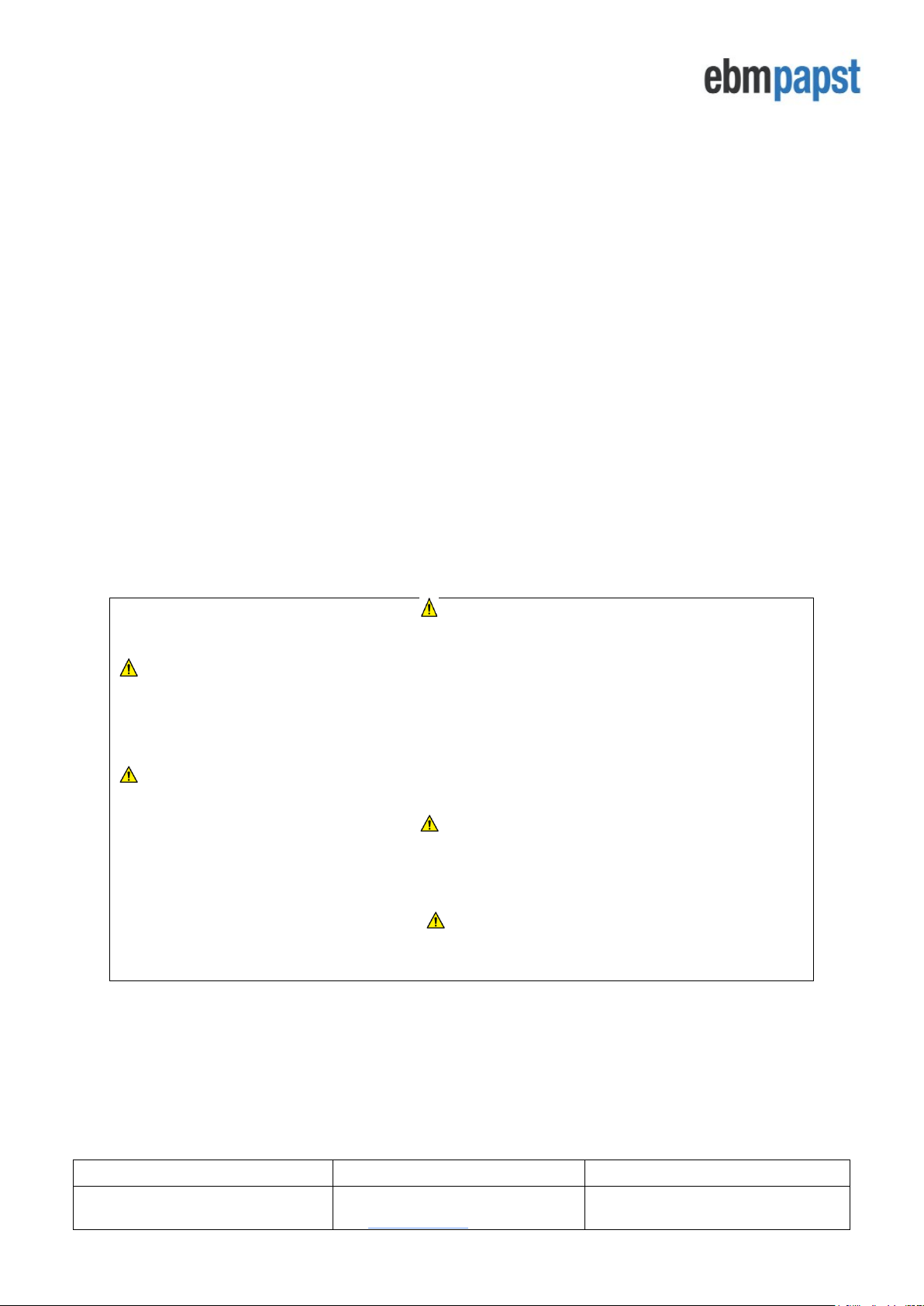
4.4 Fan Status screen
When the MDC has finished addressing all fans in the array, the new Modbus address and serial number of each
fan will be saved in non-volatile memory in the MDC. For large groups of fans in an array this may take some time
as the MDC must interrogate each individual fan for their serial numbers. Once completed, a “Change Fan Address”
prompt screen will appear in case it is desirable to change the fan addressing order.
These procedures will only happen once per array. The MDC will then default to ‘Monitor’ operating mode and the
status screen of Fan 1 will be displayed as shown in Figure 6 below:
Figure 6 - Fan status screen
From now on, the operating mode can be changed using the Main Menu screen which is accessible by pressing
the BACK button twice whilst on Fan 1 status screen. See Section 5.0 Operating Modes for more details.
There are several parameters displayed for each fan:
• Fan Condition – Healthy / Alarm / Warning / No Comms
• Warnings – Description of warnings being experienced by the fan
• Power – Power consumption (W)
• Speed – Real-time fan speed (RPM)
• Motor temperature -
o
C
• Electronics Temperature -
o
C
• Hours Run – Number of fan operational hours
• Fan control - % of maximum input signal
• Serial Number – Manufacturing serial number
There is a maximum of four lines on the display screen. To display a different monitoring parameter, use the ‘UP’
and ‘DOWN’ buttons to scroll through the information for each fan. Three parameters can be displayed at a time
The fan number and condition header are always present when the fan is being monitored. A fan can have one of
the following conditions at any given time:
• Healthy - When the fan is fully operational
• Alarm - When the fan has one or more alarms
• Warning - When the fan has one or more warnings
• No Comms - When the fan or the controller has lost communication with the Modbus network
The fan conditions Alarm, Warning and No Comms are discussed in further detail on Section 6.0 Fault Indication.
To change to a different fan in the array use the ENTER / BACK buttons to scroll through the fan array.
Parameters
being monitored
All Fans Healthy:
Green LED on
Yellow and Red LEDs off
Header with Fan Number and
Fan Condition
Operating and Maintenance Instructions
210-OMI14229-Iss2
Operation & Maintenance Instructions
Page 12 of 45
© ebm-papst UK Ltd 2018
Chelmsford Business Park Chelmsford Essex CM2 5EZ
Telephone: +44(0)1245468555 Fax: +44(0)1245466336
e-mail sales@uk.ebmpapst.com
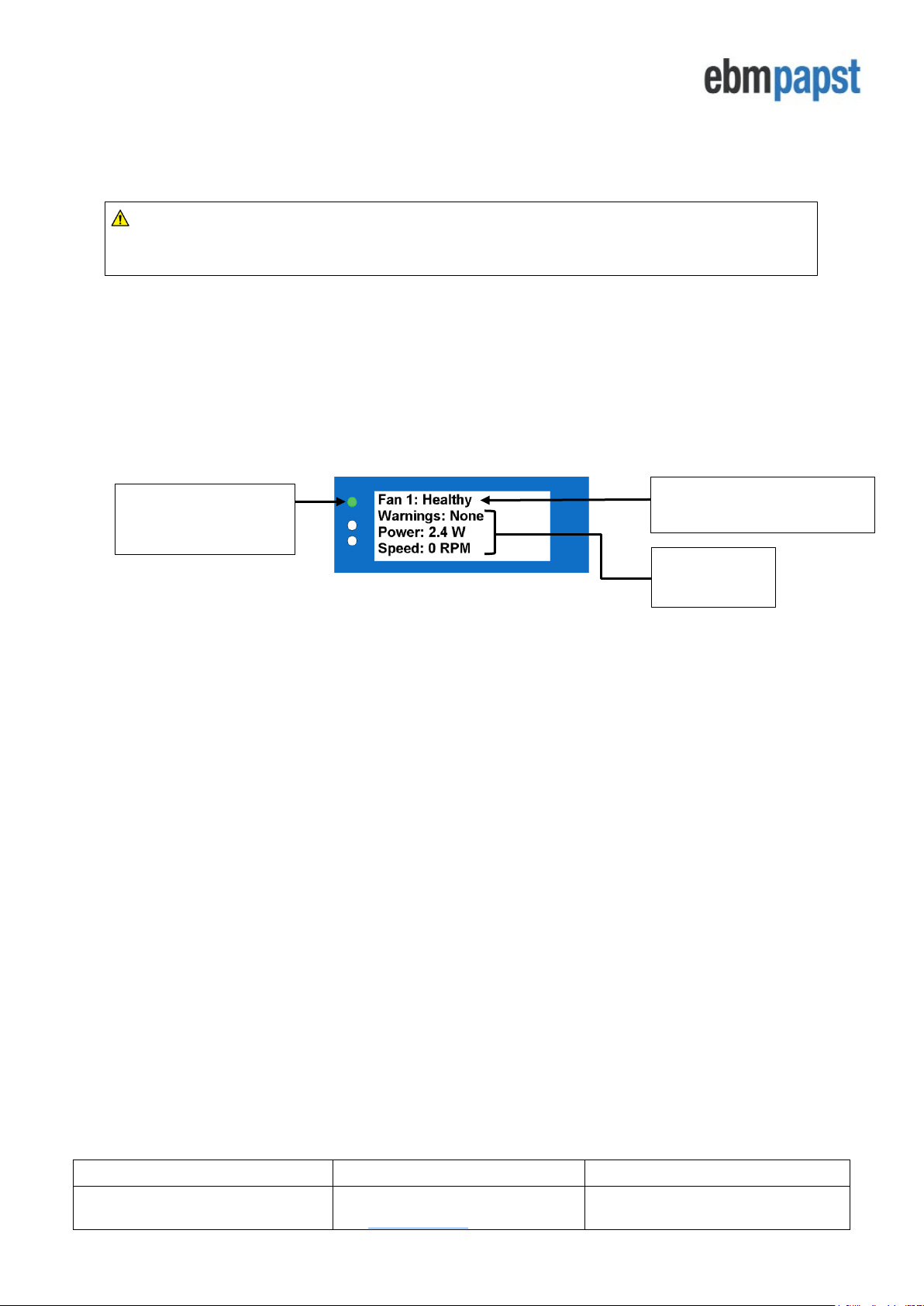
4.5 Power Meter screen
The power meter screen as shown in Figure 7 below is accessible by pressing the ENTER button when
displaying the status screen of the last fan in the array. See H6 – Status.
Figure 7 – Power meter screen
The total power consumption is a real-time measurement and consists of the sum of the power consumption from
each fan (in Watts) converted into Kilowatts. For larger fan arrays it may take some time to read this value the first
time as the MDC is polling several registers from each fan in order to derive the individual fan power which will then
be converted into total fan array power consumption.
IMPORTANT
If a fault occurs to one of more fans whilst the Power Meter Screen is being displayed, the MDC will remain on
the Power Meter Screen and will switch on the red LED for alarms and/or communication loss or the yellow
LED for warnings. After leaving the Power Meter screen, the MDC will automatically display the fan
experiencing an alarm or a communication loss.
4.6 Changing the fan addressing order
The fan auto-addressing procedure is described in 4.3.2 Auto addressing fans using the fan’s serial numbers.
The automatic assignment of Modbus addresses to fans can be inconvenient for the user as the preference for the
fan addresses may be to follow a logical addressing based on the position of the fans in the array or building. For
this reason, it is possible to individually re-address each fan such that their Modbus addresses and fan numbers
match the equipment or building layout.
This option becomes available in the main menu under ‘Fan Re-Addressing’ option once the fans have initially been
found and auto-addressed by the MDC. Under this option, a list of fans is displayed where it is possible to see each
fan’s Fan number, Modbus address and serial number. See the “Address” part of H1 – Fan Addressing - New Fan
Array -Initial Setup.
By selecting a fan and pressing ENTER, it is possible to assign a different Fan number & Modbus address to the
selected fan using UP or DOWN buttons and then pressing ENTER again.
Note: As a fan changes its fan number and address, the fan currently staying at that target fan number
and address will be changed to the selected fan’s old fan number and address - effectively “swapping” them
Note: This feature is not available when using the controller with only one fan
Note: It is not possible to assign an address outside the address range derived during the auto-addressing
process as a fan address is linked to the fan number e.g. if using the MDC with a 4-fan array, the MDC cannot
have one of the fans at Modbus address 6 because its fan number would have been 5
Indication of Fan Array Size

Operating and Maintenance Instructions
210-OMI14229-Iss2
Operation & Maintenance Instructions
Page 13 of 45
© ebm-papst UK Ltd 2018
Chelmsford Business Park Chelmsford Essex CM2 5EZ
Telephone: +44(0)1245468555 Fax: +44(0)1245466336
e-mail sales@uk.ebmpapst.com
5.0 Operating Modes
5.1 General
The MDC can be configured to operate in four different modes:
• Monitor (factory set to this mode)
• Monitor & Control
• Constant Volume / Constant Pressure
• Modbus Relay
In “Monitor” and “Modbus Relay” modes the fans remain in their factory default settings. In “Monitor & Control” and
“Constant Volume / Constant Pressure” modes the MDC automatically changes the settings of each fan to allow
speed control via Modbus opposed to the factory settings of 0-10V analogue input control and therefore the
analogue inputs of the fan motors are disabled. There is no need to manually change individual fan settings, the
MDC does this automatically.
In addition to changing the operational mode of the MDC, it is also possible to change different parameters of the
fans and the controller such as RPM limits, Control Voltage Cap, Input Voltage Cap, Alarm Output, BMS Settings,
LCD Brightness, Main Menu lock as well as to reset the fans and controllers to their factory default condition.
5.2 Accessing the main menu
Modifying the operational mode and configuring the control parameters is available via the Main Menu, which can
be accessed using the keypad see H6 – Status. Scroll though the fans using the BACK button until Fan 1 status
screen is shown. Pressing the BACK button twice again accesses the Main Menu. It is possible to prevent
unauthorised access to the main menu by locking it. Details on activating the lock and the key sequence to allow
Main Menu access is detailed on 5.7 Advanced Settings Submenu
Most of the options in the Main Menu and its submenus can also be modified remotely by a Modbus Master
connected to the MDC’s RS485 slave port. See Appendix E – Modbus Holding Registers for more details.
IMPORTANT
The Main Menu is intended for configuration purposes only and therefore the entire controller’s monitor and/or
control operations will be halted whilst on the Main Menu or any of its submenus except ‘Set Speed’ submenu.
Halting does not apply if the configuration parameters are changed via the RS485 slave port whilst the MDC is
in a status or power screen, however, most changes made in the Main Menu either locally or remotely will
trigger a power cycle to both fans and controller in order to activate the new parameters.
The four operational modes are selectable in the Main Menu using menu option ‘Operation Mode’. Please note
that all fans must have been addressed for this option to become available.
5.3 Monitor mode (default operation)
In “Monitor” operating mode the fans in the array are following a speed control command from a separate source,
for example a 0-10VDC or 4-20mA control, or if they have been configured to adapt based on a sensor input to the
fan. In this operating mode, the MDC is just a monitoring device extracting information from the Modbus registers
in each fan.
In “Monitor” operating mode it is also possible to monitor either a pressure differential or calculate the volume flow
in real-time by using an external DS85 differential pressure sensor connected to the MDC. This information will be
displayed in the Power Meter screen. See H7 – Operation Mode – Monitor for how to enter Monitor mode.
Operating and Maintenance Instructions
210-OMI14229-Iss2
Operation & Maintenance Instructions
Page 14 of 45
© ebm-papst UK Ltd 2018
Chelmsford Business Park Chelmsford Essex CM2 5EZ
Telephone: +44(0)1245468555 Fax: +44(0)1245466336
e-mail sales@uk.ebmpapst.com
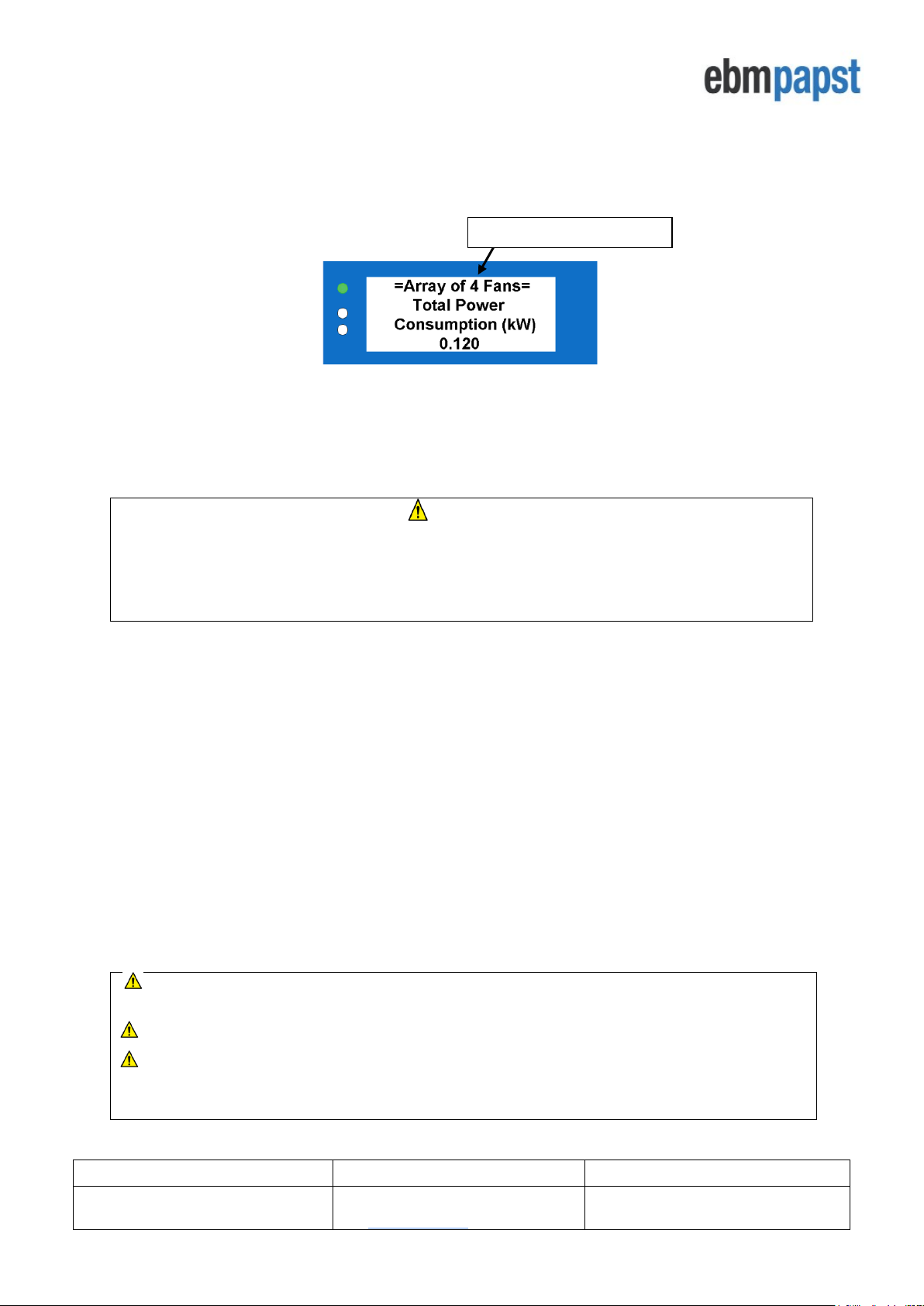
5.3.1 Monitor mode: single fan connection
Figure 8 – Typical wiring diagram for Monitor operating mode - single fan monitoring
CAUTION: Danger of damaging the fan if two power supplies are connected at the same time
Do not connect the fan’s 10Vdc output to the controller if powering the controller from an external supply
IMPORTANT:
It is not recommended to use the +10Vdc supply from a single fan to power the controller as the controller may
switch off if certain faults are experienced by the fan. Furthermore, the LCD brightness would be dimmed if using
only one 10Vdc 10mA supply. It is recommended that an external +24V DC power supply is used to power the
MDC unit for all installations.
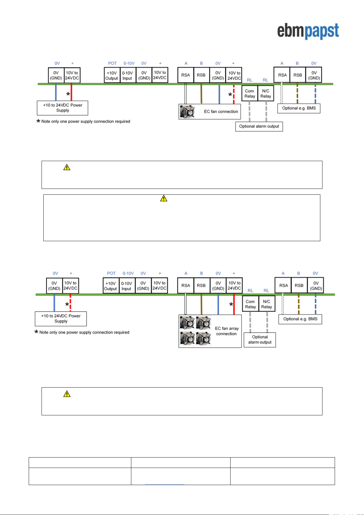
5.3.2 Monitor mode: multiple fan connection
Figure 9 - Typical wiring diagram for Monitor operating mode - multiple fan monitoring
CAUTION: Danger of damaging the fan if two power supplies are connected at the same time
Do not connect the fan’s 10Vdc output to the controller if powering the controller from an external supply
 Loading...