

Eberspächer HYDRONIC L Series, HYDRONIC L D 30 W N, HYDRONIC L D 35 W N, HYDRONIC L D 16 W N, HYDRONIC L D 24 W N Technical Description, Installation, Operation And Maintenance Instructions
HYDRONIC L
Technical description, installation,
operation and maintenance instructions.
Water heaters for diesel fuel, operating
operating independently of an engine.
25 1818 90 99 25
11.2008
Heater Order No. – normal version Order No. – compact version
HYDRONIC L D 16 W N 25 2165 02 00 00 – – –
HYDRONIC L D 24 W N 25 1817 02 00 00 25 1817 05 00 00
HYDRONIC L D 30 W N 25 1818 02 00 00 25 1818 05 00 00
HYDRONIC L D 35 W N 25 1819 02 00 00 25 2041 05 00 00

2
6
5
4
3
2
1
• Contents...................................................................................................... 2
• Concept of this manual ................................................................................ 3
• Special text structure, presentation and picture symbols .............................. 4
• Important information before starting work ................................................... 4
• Statutory regulations ................................................................................ 5, 6
• Safety instructions for installation and operation ........................................... 7
• Accident prevention .................................................................................... 7
• Scope of supply / additional parts ............................................................ 8, 9
• Technical data, heater ................................................................................ 10
• Technical data, water pump ....................................................................... 11
• Pumping and pressure loss characteristic curves ....................................... 11
• Main heater dimensions, normal version .................................................... 12
• Main heater dimensions, compact version ................................................. 12
• Permissible installation position and fastening of the heater ....................... 13
• Installation location .................................................................................... 14
• Installing the heater in a box ...................................................................... 15
• Nameplate ................................................................................................. 15
• Exhaust system (pipes) ........................................................................ 16, 17
• Combustion air system .............................................................................. 18
• Connection to the cooling water circuit ...................................................... 19
• Water circuit .............................................................................................. 19
• Fuel supply ....................................................................................... 20 – 22
• Structure of the heater ............................................................................... 23
• Special features of the heater..................................................................... 23
• Operation instructions / important information for operation ....................... 23
• Initial commissioning of the heater ............................................................. 23
• Functional description ................................................................................ 24
• Control and safety devices / EMERGENCY OFF ........................................ 25
• Heater wiring ............................................................................................. 26
• Parts list / circuit diagram, heater – Part 1 .................................................. 27
• Parts list / circuit diagram, heater – Part 2 .................................................. 28
• Parts list / circuit diagram, control units ...................................................... 29
• Parts list, EasyStart control units ................................................................ 33
• Circuit diagrams, EasyStart control units ............................................ 31 – 33
• If any faults occur, please check the following items ................................... 34
• Troubleshooting ......................................................................................... 34
• Maintenance instructions ........................................................................... 34
• Changing components .............................................................................. 34
• Service ...................................................................................................... 34
• Certifications .............................................................................................. 35
• Disposal .................................................................................................... 35
• EC Declaration of Conformity ..................................................................... 35
• Index ........................................................................................................ 36
• List of abbreviations .................................................................................. 37
Introduction
1
Chapter Title Contents Page
Contents
Introduction
Product information
Installation
Operation and function
Electrical system
Faults
Maintenance
Service
Environment
Lists
7
8

3
Concept of this manual
This manual aims to support the service company
installing the heater and to provide the user with all
important information about the heater.
The manual has been divided into 8 chapters to make it
easier to find the corresponding information quickly.
Introduction
Here you find important introductory information
about installation of the heater and about the
structure of the manual.
Product information
Here you will find information about the scope of
supply, the technical data and the dimensions of
the heater.
Installation
Here you will find important information and
instructions referring to installation of the heater.
Operation and function
Here you will find information about the operation
and function of the heater.
Electrical system
Here you will find information about the heater's
electrics and electronic components.
Troubleshooting / maintenance / service
Here you will find information about possible
faults, troubleshooting, servicing / maintenance
and the service hotline.
Environment
Here you will find information about certification
and disposal of the heater together with the EC
Declaration of Conformity.
Lists
Here you will find the key word list and abbreviations list.
4
Introduction
1
5
6
1
2
3
7
8
4
Introduction
1
Special text structure, presentation and
picture symbols
This manual uses special text structures and picture
symbols to emphasize different contents.
Please refer to the following examples for their meanings and appropriate action.
Special text formats and presentations
A dot (•) indicates a list which is started by a heading.
If an indented dash (–) follows a dot, this list is subordinate to the dot.
Picture symbols
Regulation!
This picture symbol with the remark "Regulation!" refers
to a statutory regulation.
Failure to comply with this regulation results in expiry of
the type-approval for the heater and preclusion of any
guarantee and liability claims on J. Eberspächer GmbH
& Co. KG.
Danger!
This picture symbol with the remark "Danger!" refers to
the risk of a fatal danger to life and limb.
Under certain circumstances, failure to comply with
these instructions can result in severe or life-threatening
injuries.
Important!
This picture symbol with the remark "Caution!" refers to
a dangerous situation for a person and / or the product.
Ignoring this information can result in injuries to people
and / or damage to machinery.
These remarks contain recommendations for use and
useful tips for installation of the heater.
Important information before starting work
Range of application of the heater
The water heater operating independently of an engine
is intended for installation in the following vehicles:
• All types of motor vehicles, especially buses and
coaches
• Construction machinery
• Agricultural machinery
• Boats, ships and yachts
• Rail vehicles
The heater cannot be installed in vehicles used for the
transport of dangerous goods according to ADR.
Intended purpose of the heater (via the vehicle's
own heat exchanger)
• Pre-heating, de-misting windows
• Heating and keeping the following warm:
– Driver and working cabs
– Freight compartments
– Ship's cabins
– Passenger and crew compartments
– Vehicle engines and units
On account of its functional purpose, the heater is not
approved for the following applications:
• Long-term continuous operation, e.g. for pre-heating
and heating of:
– Residential rooms
– Garages
– Work huts, weekend homes and hunting lodges
– Houseboats, etc.
Important!
Safety instructions for the range of application and
proper, intended use!
The heater must only be used and operated for the
range of application stated by the manufacturer and in
compliance with the operation instructions included with
every heater.
Please note!
Please note!

5
Statutory regulations
The Federal Road Transport Directorate has issued an
“EC type approval” and an “EMC type-approval” for
the heater for installation in motor vehicles and with
the following official type-approval marks, noted on the
heater name plate.
HYDRONIC L EC- e1 00 0030
EMC- e1 031076
The Federal Railway Office has issued a “type approval
to Art 33 EBO” for installation of the heater in rail vehicles; the vehicle has the following official type approval:
HYDRONIC L EBA-32AZ3/0110/05
Regulations!
Directive 2001 / 56 / EC of the European
Parliament and the Council
• Position of the heater
– Parts of the structure and other components near
the heater must be protected from excessive heat
exposure and possible fuel or oil contamination.
– The heater must not pose a fire hazard even when it
overheats. This requirement is deemed to be fulfilled
if adequate clearance is ensured for all parts during
installation, sufficient ventilation is provided and
fireproof materials or heat shields are used.
– The heater must not be mounted in the passenger
compartment of vehicles in class M
1
, M2, M3 and
N. But a heater in a hermetically sealed enclosure
which otherwise complies with the conditions stated
above may be used.
– The factory nameplate or duplicate of it must be
affixed so that it can still be easily read when the
heater is installed in the vehicle.
– All appropriate precautions must be taken when
arranging the heater to minimise the risk of injuries
to persons or damage to other property.
Introduction
1
• Fuel supply
– The fuel intake connection must not be located in
the passenger compartment and must be sealed
with a properly closing lid to prevent any fuel leaks.
– In heaters for liquid fuel where the heater fuel is
separate from the vehicle fuel, the type of fuel and
intake connection must be clearly identified.
– A warning sign is to be fixed to the intake connec-
tion indicating that the heater must be switched off
before refuelling.
• Exhaust system
– The exhaust outlet must be arranged so as to
prevent any penetration of exhaust fumes into the
vehicle interior through the ventilation system, warm
air intakes or open windows.
• Combustion air intake
– The air for the heater's combustion chamber must
not be sucked in from the vehicle's passenger
compartment.
– The air intake must be arranged or protected in such
a way that it cannot be blocked by other objects.
• Operating status display
– A clearly visible operating display in the user's field
of vision must indicate when the heater is switched
on an off.
Statutory regulations
Regulation
The laying of fuel lines and installation of additional fuel
tanks must comply with Art 45 and 46 of the StVZO
(German road vehicle licensing regulations).
Extract from Art 45 and 46 StVZO:
• Fuel tanks in buses and coaches must not be located
in the passenger compartment or driver's cab. They
must be positioned in such a way that if a fire occurs
the exits are not at immediate risk.
• Fuel lines in buses and coaches must not be located
in the passenger compartment or driver's cab.
• The heater may not be installed in classes M
1
and N1,
as the end-of-life vehicles regulations (EC End-of-Life
Vehicles Directive 2000/53/EC) is not complied with.

6
Please note!
Introduction
1
Regulations
Additional regulations for certain vehicles named
in Directive 94 / 55 / EC (ADR Framework Directive)
Scope
This appendix applies to vehicles for which the special
provisions of Directive 94 / 55 / EC apply to combustion
heaters and their installation.
Definition of terms used
For the purposes of this appendix, the vehicle designations „EX / II“, „EX / III“, „AT“, „FL“ and „OX“ according
to Chapter 9.1 of Annex B of Directive 94 / 55 / EC are
used.
Technical regulations
General provisions (EX / II, EX / III, AT, FL and OX
vehicles)
Avoid heating and ignition
The combustion heaters and their exhaust gas routing
shall be designed, located, protected or covered so as
to prevent any unacceptable risk of heating or ignition
of the load. This requirement shall be considered as
fulfilled if the fuel tank and the exhaust system of the
appliance conform to provisions in 3.1.1.1 and 3.1.1.2.
Compliance with these regulations shall be checked in
the complete vehicle.
Fuel tanks
Fuel tanks for supplying the heater shall conform to the
following regulations:
• In the event of any leakage, the fuel shall drain to the
ground without coming into contact with hot parts of
the vehicle or the load;
• fuel tanks containing petrol shall be equipped with
an effective flame trap at the filler opening or with a
closure enabling the opening to be kept hermetically
sealed.
Exhaust system and exhaust pipe layout
The exhaust system as well as the exhaust pipes shall
laid out or protected to avoid any danger to the load
through heating or ignition. Parts of the exhaust system
situated directly below the fuel tank (diesel) shall have
a clearance of at least 100 mm or be protected by a
thermal shield.
Switching on the combustion heater
The combustion heater may only be switched on manually. Automatic switching on via a programmable switch
is not permitted.
EX / II and EX / III vehicles
Combustion heaters for gaseous fuels are not permitted.
FL vehicles
Combustion heaters must be able to be taken out of
service/disabled at least by the methods described in
the following:
a) Switching off manually in the driver‘s cabin
b) Switching off the vehicle‘s engine; in this case the
heater may be manually switched back on by the
vehicle driver;
c) Starting up of a feed pump installed in the vehicle for
the dangerous goods carried.
Combustion heater after-run
After-running of the switched off combustion heater
is permitted. In the cases named in the „FL vehicles“ paragraph under letters b) and c) the supply of combustion
air must be interrupted by suitable means after a maximum after-run period of 40 seconds. Only combustion
heaters whose heat exchangers are verifiably not damaged by the reduced after-run period of 40 seconds
beyond their usual use period may be used.
• Compliance with the statutory regulations, the additional regulations and safety instructions is prerequisite
for guarantee and liability claims.
Failure to comply with the statutory regulations and
safety instructions and incorrect repairs even when
using original spare parts make the guarantee null
and void and preclude any liability for J. Eberspächer
GmbH & Co. KG.
• Subsequent installation of this heater must comply
with these installation instructions.
• The statutory regulations are binding and must also be
observed in countries which do not have any special
regulations.
• When the heater is to be installed in vehicles
not subject to the German Ordinance for the Registra-
tion of Motor Vehicles (StVZO), for example ships, the
specially valid regulations and installation instructions for
these special applications must be observed.
• Installation of the heater in special vehicles must comply with the regulations applying to such vehicles.
• Other installation requirements are contained in the
corresponding sections of this manual.

7
Safety instructions for installation
and operation
Danger!
Risk of injury, fire and poisoning
• Disconnect the vehicle battery before starting any kind
of work.
• Before working on the heater, switch the heater off
and let all hot components cool down.
• The heater must not be operated in enclosed rooms,
e.g. in the garage or multi-storey car park.
Caution!
Safety instructions for installation and operation
• The heater must only be installed by a JE partner authorised by the manufacturer according to the instructions in this manual and possibly according to special
installation recommendations; the same applies to
any repairs to be carried out in the case or repairs or
guarantee claims.
• Repairs by non-authorised third-parties or with not
original spare parts are dangerous and therefore not
allowed. They result in expiry of the type permit of the
heater; consequently, when installed in motor vehicles
they can cause expiry of the vehicle operating licence.
• The following measures are not allowed:
– Changes to components relevant to the heater.
– Use of third-party components not approved by
J. Eberspächer GmbH & Co. KG.
– Nonconformities in installation or operation from the
statutory regulations, safety instructions or specifications relevant to safe operation as stated in the
installation instructions and operating instructions.
This applies in particular to the electrical wiring, fuel
supply, combustion air system and exhaust system.
• Only original accessories and original spare parts must
be used during installation or repairs.
• Only original accessories and spare parts may be
used for installation or repairs.
• Only the controls approved by Eberspächer may be
used to operate the heater.
The use of other controls can result in malfunctions.
• Before the heater is installed again in another vehicle,
rinse the heater parts carrying water with clear water.
Introduction
1
• When carrying out electric welding on the vehicle, the
plus pole cable at the battery should be disconnected
and placed at ground to protect the controller.
• The heater must not be operated where there is a risk
of an accumulation of flammable vapours or dust, for
example close to
– fuel depot
– coal depot
– wood depot
– grain depots etc.
• The heater must be switched off when refuelling.
• When the heater is mounted in a safety housing etc.,
the installation compartment of the heater is not a
stowage compartment and must be kept clear.
In particular fuel canisters, oil cans, spray cans, gas
cartridges, fire extinguishers, cleaning rags, items of
clothing, paper etc. must not be stored or transported
on or next to the heater.
• Defect fuses must only be replaced by fuses with the
prescribed rating.
• If fuel leaks from the heater fuel system, arrange for
the damage to be repaired immediately by a JE service partner.
• When topping up the coolant, only use the coolant
permitted by the vehicle manufacturer, see the vehicle
operating manual. Any blending with unpermitted
coolant can cause damage to the engine and heater.
• After-running of the heater must not be interrupted
prematurely e.g. by pressing the battery disconnecting
switch, apart from in the case of an emergency stop.
Accident prevention
General accident prevention regulations and the corresponding workshop and operation safety instructions
are to be observed.

8
Product information
2
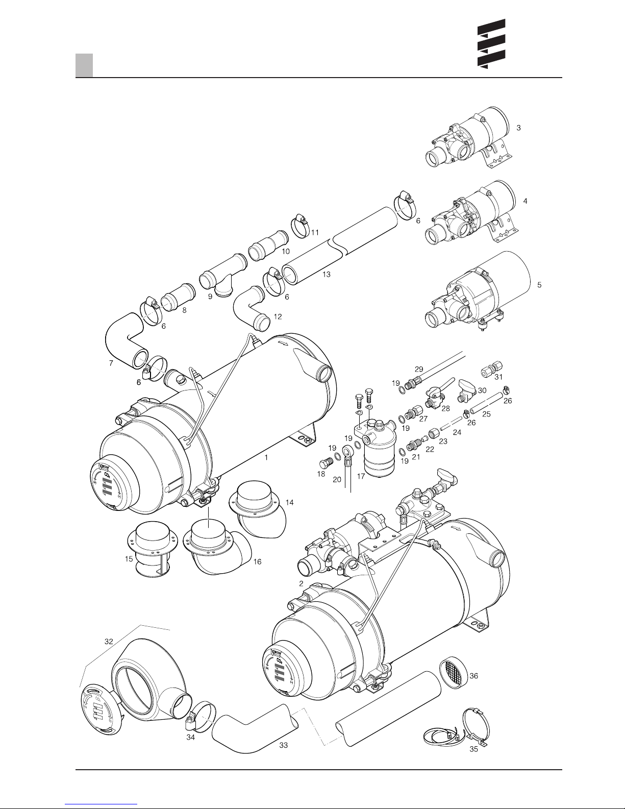
Scope of supply
Figure No. Designation Order No.
1 HYDRONIC 16 – 24 volt 25 2165 02 00 00
Normal version
1 HYDRONIC 24 – 24 volt 25 1817 02 00 00
Normal version
2 HYDRONIC 24 – 24 volt 25 1817 05 00 00
Compact version
1 HYDRONIC 30 – 24 volt 25 1818 02 00 00
Normal version
2 HYDRONIC 30 – 24 volt 25 1818 05 00 00
Compact version
1 HYDRONIC 35 – 24 volt 25 1819 02 00 00
Normal version
2 HYDRONIC 35 – 24 volt 25 2041 05 00 00
Compact version
The following additional parts are required to run the
heater:
• Additional parts for connection to the water circuit
• Additional parts for the fuel supply
• Additional parts for the exhaust system
• Control unit
Additional parts which have to be ordered
separately
Figure No. Designation Order No.
3 FLOWTRONIC 5000 25 1818 29 00 00
4 FLOWTRONIC 5000S 25 1818 30 00 00
5 FLOWTRONIC 6000S 25 1818 27 00 00
6 Hose clip, ø 40-47 mm 152 00 158
7 Hose elbow, ø 38 mm 360 00 300
8 Connection pipe, ø 38 mm 25 1214 89 00 21
9 T-piece, ø 38-38-38 25 1371 89 04 00
10 Reducer, ø 38/28 mm 25 1214 89 00 19
11 Hose clip, ø 32-39 mm 152 61 097
12 Pipe elbow, ø 38 mm 25 1214 89 00 03
13 Water hose, ø 38 mm 360 75 096
14 Exhaust pipe socket, ø 70 mm 25 2025 89 01 00
15 Exhaust pipe socket, ø 70 mm 22 1000 40 04 00
16 Exhaust pipe elbow, ø 70 mm 22 1000 40 03 00
17 Fuel filter 330 00 052
18 Banjo bolt, M14 x 1.5 104 10 040
19 Sealing ring, A14 x 18 323 16 006
20 Fuel suction line 25 1698 05 03 00
21 Screw fixing, M14 x 1.5 266 42 004
22 Spherical liner 263 35 080
23 Union nut, M14 x 1.5 116 10 040
24 Fuel pipe,
Outer diameter ø 6 x 1 (Cu)
25 Fuel hose,
Inner diameter ø 5 x 3 360 75 350
26 Hose clip, ø 11 mm 10 2063 01 10 98
27 Screw fixing, M14 x 1.5 25 1706 05 01 00
28 Ball valve, M14 x 1.5 330 00 019
29 Fuel return line 25 1698 05 04 00
30 Valve 330 00 210
31 Reducing coupling 8 / 6 266 00 026
32 Shroud with hose connection 22 1000 40 06 00
33 1 m flexible hose, ø 60 mm 10 2114 31 00 00
34 Hose clip 10 2064 05 00 70
35 Air hose fixing kit 22 1000 50 02 00
36 Plastic grille 25 1688 80 06 00
* The fuel pipe must be purchased from a specialist
dealer.
For further additional parts, see additional parts
catalogue.
Please note!
9
Product information
2
Scope of supply
10
Product information
2
Important!
Safety instructions for technical data
Failure to comply with the technical data can result in
malfunctions.
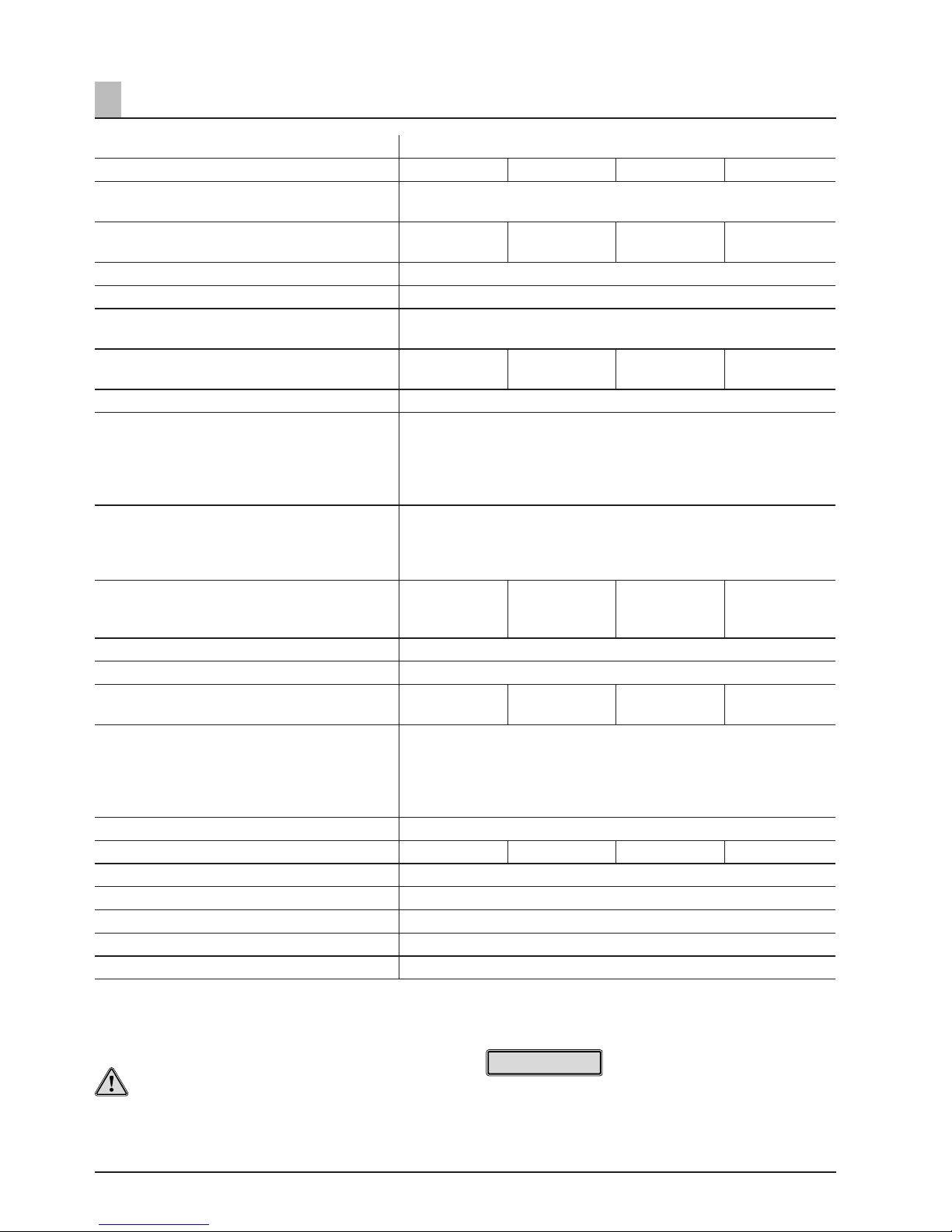
Technical data
HYDRONIC L
Type
D 16 W N D 24 W N D 30 W N D 35 W N
Heating medium Mixture of water and coolant
(max. 50 % coolant)
Heat flow in watts
(at ambient temperature 20 °C)
16 000 24 000 30 000 35 000
Temperature values – at water inlet ON 73 °C / OFF 78 °C
Temperature values – at water outlet ON 85 °C / OFF 118 °C
Fuel Diesel – commercially available (DIN EN 590)
Heating oil EL (DIN 51603)
Fuel consumption
(at ambient temperature –10 °C)
2.0 l/h 2.9 l/h 3.65 l/h 4.2 l/h
Rated voltage 24 volt
Operating range
• Lower voltage limit:
An undervoltage protection installed in the
control box switches off the heater if the voltage limit is reached.
19 volt
• Upper voltage limit:
An overvoltage protection installed in the con-
trol box switches off the heater if the voltage
limit is reached.
30 volt
Electrical power consumption
(in combustion mode / without circulation
pump)
60 watt 80 watt 105 watt 120 watt
Water content of the heat exchanger approx. 2 l
Water volume of the water circuit min. 10 l
Minimum throughput of the heating medium
(±200 l/h)
1400 l/h 2000 l/h 2600 l/h 3000 l/h
Permissible ambient temperature in operation:
during transport / storage:
for the combustion air:
Pumped fluid:
–40 °C to +85 °C
–40 °C to +100 °C
< 60 °C
–40 °C to +90 °C,
briefly up to +120 °C
Operating pressure (water circuit) < 2.5 bar
CO
2
values (vol .%) 9 – 11 9 – 11 9 – 11 9,5 – 11,5
CO in the exhaust < 0.04
Smoke spot no. (Bacherach) < 4
Weight approx. 18 kg
Interference suppression class VHF 4 / SW 3 / MW 5 / LW 3 to DIN 57879 / Part 1 VDE 0879
Protection IP 64
Please note!
Provided no limit values are given, the technical data
provided is with the usual heater tolerances of ±10 % at
rated voltage, 20 °C ambient temperature and reference
altitude Esslingen.

11
Product information
2
Important!
Safety instructions for technical data
Failure to comply with the technical data can result in
malfunctions.
Technical data
FLOWTRONIC 5000
Heating medium Mixture of water and coolant
(max. 50 % coolant)
Delivery rate 5200 l/h ±10 % at 0.2 bar delivery pressure
Operating pressure, water circuit max. 2 bar
Weight (without bracket, clip and coolant) 2.14 kg
Rated voltage 24 volt
Operating range 20 – 28 volt
Power consumption
at 5200 l/h and 0.2 bar delivery pressure
104 watt ±10 %
Interference suppression class 3
to DIN 57879 / Part 1 VDE 0879
Protection IP 54A
to DIN 40 050 Sheet 1
Electrical fusing for third party controls 15 A
Temperature conditions
–40 °C to 90 °C short-term (15 min) +115 °C
Heating medium
–40 °C to 90 °C short-term (15 min) +115 °C
Ambient, operating
Dry running No
Blocking The engine remains undamaged within a period of max
6 seconds.
Shaft - impeller connection Mechanical seal
Pumping and pressure loss characteristic curves
Please note!
Volumetric flow (with water at 20 °C)
Flow resistance (when pump at a standstill)
• Provided no limit values are given, the technical data
provided is with the usual heater tolerances of
±10 % at rated voltage, 20 °C ambient temperature
and reference altitude Esslingen.
• The FLOWTRONIC 5000 water pump is installed in
compact heaters.
• If water pumps are ordered separately, please refer to
the documentation provided for the relevant technical
data, installation positions, etc.
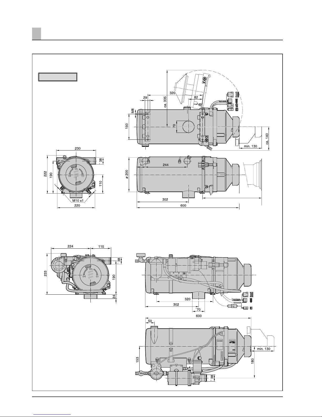
12
Main dimensions
Please note!
• If there is sufficient space the
shroud can be removed, the burner
swung out and the header pipe
dismantled – see sketch.
• The normal version dimensions also
apply to the compact version.
• The main dimensions also apply
when the shroud is mounted with
hose connection.
Heaters – compact version
Product information
2
min. 375 for removing
the header pipe
Heater – normal version
 Loading...