

Page 1
1
D
S
GB
F
J. Eberspächer
GmbH & Co.
Eberspächerstr. 24
D - 73730 Esslingen
Telefon (zentral)
(0711) 939 - 00
Telefax
(0711) 939 - 0500
www.eberspaecher.com
Contents Page
Items supplied .......................................................... 2, 3
Control elements, optional ........................................ 2
Government regulations and
safety instructions concerning installation .............. 4
Technical data ........................................................... 5
Sectional drawing ..................................................... 6
Principal dimensions / Installation ........................... 7
Mounting instructions / mounting example ................ 8, 9
Permissible mounting positions ............................... 10
Documentation
for installation*
Eberspächer®
Page
Type plate .................................................................. 10
Connection to the cooling water circuit ..................... 11 – 14
Conducting the combustion air / exhaust gas ........ 15
Fuel supply ................................................................ 16 – 19
Circuit diagrams ........................................................ 20 – 25
Function ..................................................................... 26
Controls and safety devices ..................................... 27
GGVS / TRS 003 / ADR / ADR 99 –
mode of operation ..................................................... 27
* Please hand this technical description / mounting instruction
to the customer after installation of the
HYDRONIC
.
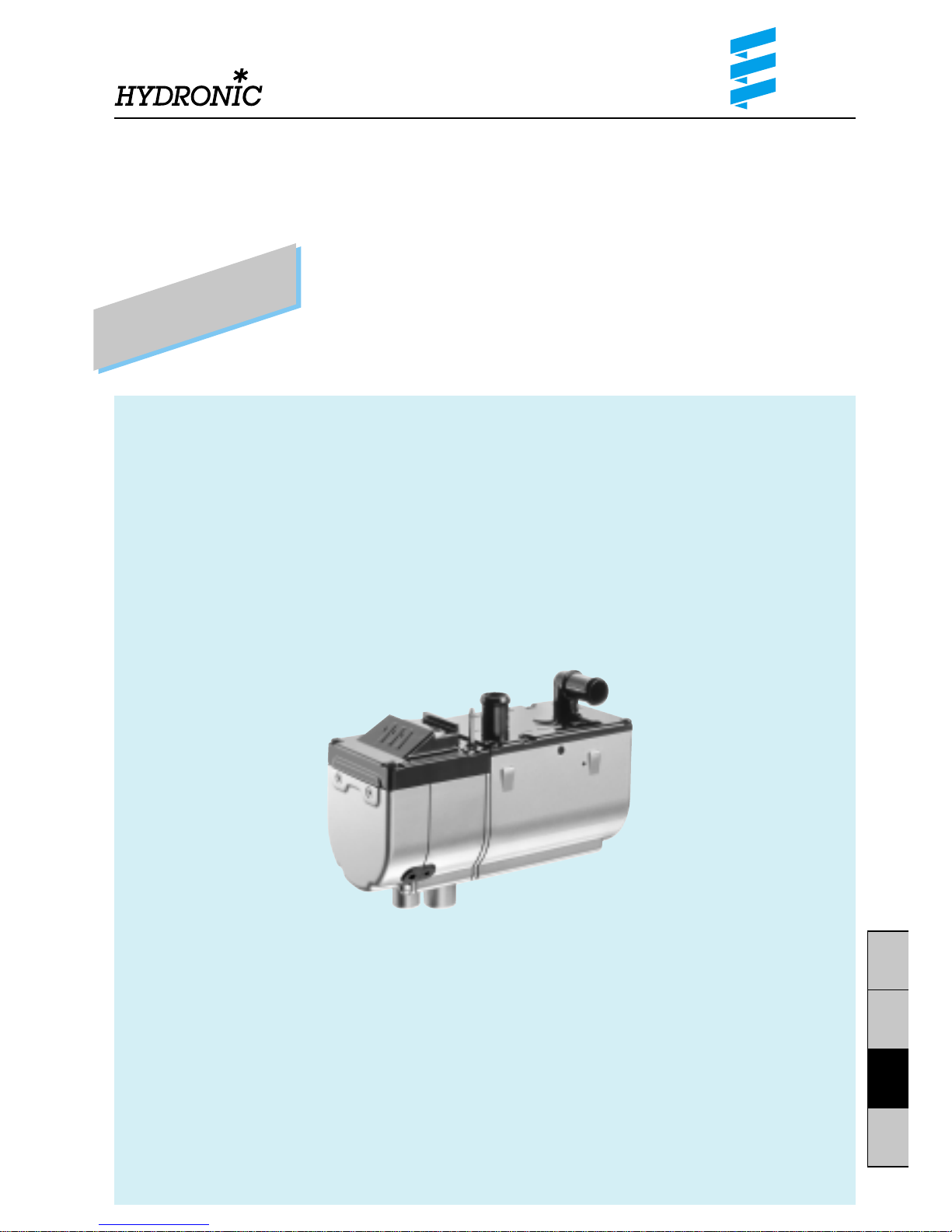
Engine-independent water heater
HYDRONIC
B 5 W S for petrol
Order No.
HYDRONIC
B 5 W S – 12 V 20 1819 05 00 00
Universal mounting kit 20 1819 80 00 00
HYDRONIC
B 5 W S – 12 V 20 1822 05 00 00
As a complete package
Subject to change
B 5 W S and D 5 W S
Technical Description
Mounting Instructions
HYDRONIC
D 5 W S for diesel
Order No.
HYDRONIC
D 5 W S – 12 V 25 2217 05 00 00
Universal mounting kit 20 1819 80 00 00
HYDRONIC
D 5 W S – 12 V 25 2228 05 00 00
As a complete package
HYDRONIC
D 5 W S – 24 V 25 2218 05 00 00
Universal mounting kit 25 2218 80 00 00
Page 2
2
D
S
GB
F
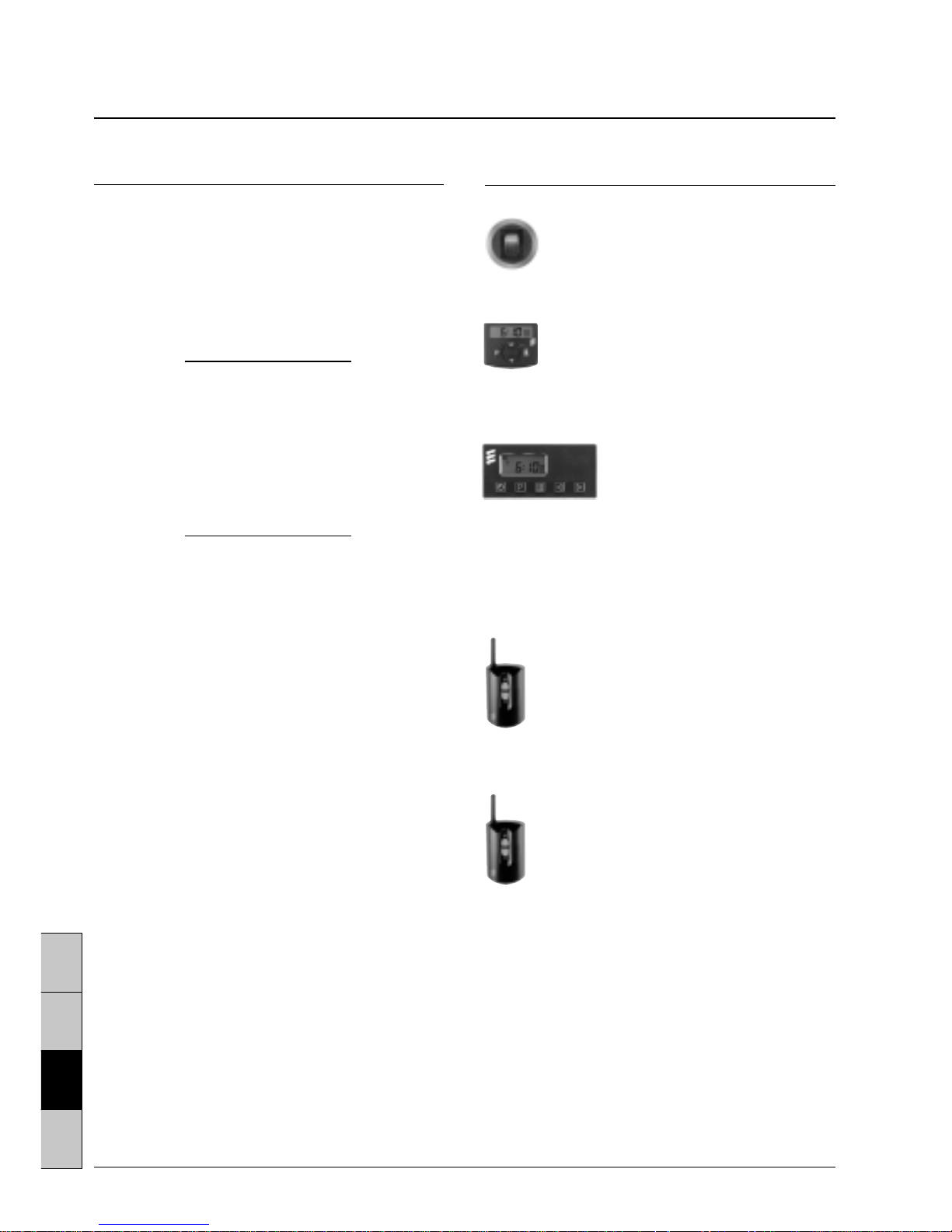
Control elements, optional
Quantity / Designation Order No.
1 Change-over switch 22 1000 31 89 00
‘heating / ventilating’ 12 / 24 volt
Can only be used in combination
with a control element.
1 Mini-clock – 12 / 24 volt 22 1000 31 31 00
1 Module clock – 12 / 24 volt 22 1000 30 34 00
with temperature preselection
1 Mounting parts for the 25 1482 70 01 00
module clock – only required
when installed with a shade
1 TP 41i radio remote control 22 1000 31 39 00
12 / 24 volt
1 TP 4i radio remote control 22 1000 30 99 00
12 / 24 volt
Please note!
Control elements must be selected in accordance
with the intended use of the
HYDRONIC
and on the
basis of the distinction: air or water heater, simple
switching on and off, programme preselection and /
or radio remote control. The control elements are
supplied with operating instructions. These are
intended to be handed over to the customer together
with the mounting and operating instructions for the
HYDRONIC
.
The TP 41i radio remote control
can be used on its own or in combination
with the mini-clock – Order No. 22 1000 31 31 00.
The mini-clock can be combined with
the TP 41i radio remote control.
The module clock can be
combined with the TP 4i
radio remote control.
The TP 4i radio remote control can only be used
in combination with the module clock.
Items supplied
Quantity / Designation Order No.
1
HYDRONIC
B 5 W S – 12 volt 20 1819 05 00 00
To be additionally ordered:
1 Universal mounting kit 20 1819 80 00 00
or
1
HYDRONIC
B 5 W S – 12 volt 20 1822 05 00 00
As a complete package*
1
HYDRONIC
D 5 W S – 12 volt 25 2217 05 00 00
To be additionally ordered:
1 Universal mounting kit 20 1819 80 00 00
or
1
HYDRONIC
D 5 W S – 12 volt 25 2228 05 00 00
As a complete package*
1
HYDRONIC
D 5 W S – 24 volt 25 2218 05 00 00
To be additionally ordered:
1 Universal mounting kit 25 2218 80 00 00
* The complete package consists of:
1
HYDRONIC
B 5 W S or D 5 W S
1 Universal mounting kit
Optional extras
1 Check valve, Ø 18 mm 254 00 070
1 Check valve, Ø 20 mm 254 00 074
1 Comfort mounting kit for engines from 2.5 l
cubic capacity 24 0132 00 00 00
The comfort mounting kit includes the following:
1 thermostat, Ø 18 mm
1 T-piece, Ø 18 mm
1 check valve, Ø 18 mm
1 water hose, Ø 18 mm
10 hose clamps
Please refer to the Extra Parts Catalogue for other
additional parts.
Attention!
Before switching on or preprogramming the heating, put
the vehicle’s heating lever (provided the vehicle is
equipped with one) to “HOT” (maximum position) and
the fan to “slowest speed” (low current consumption).
For vehicles with automatic heating, put the heating
lever to “MAX.” and the desired damper position to
“OPEN” before switching off the ignition.
Page 3
3
D
S
GB
F
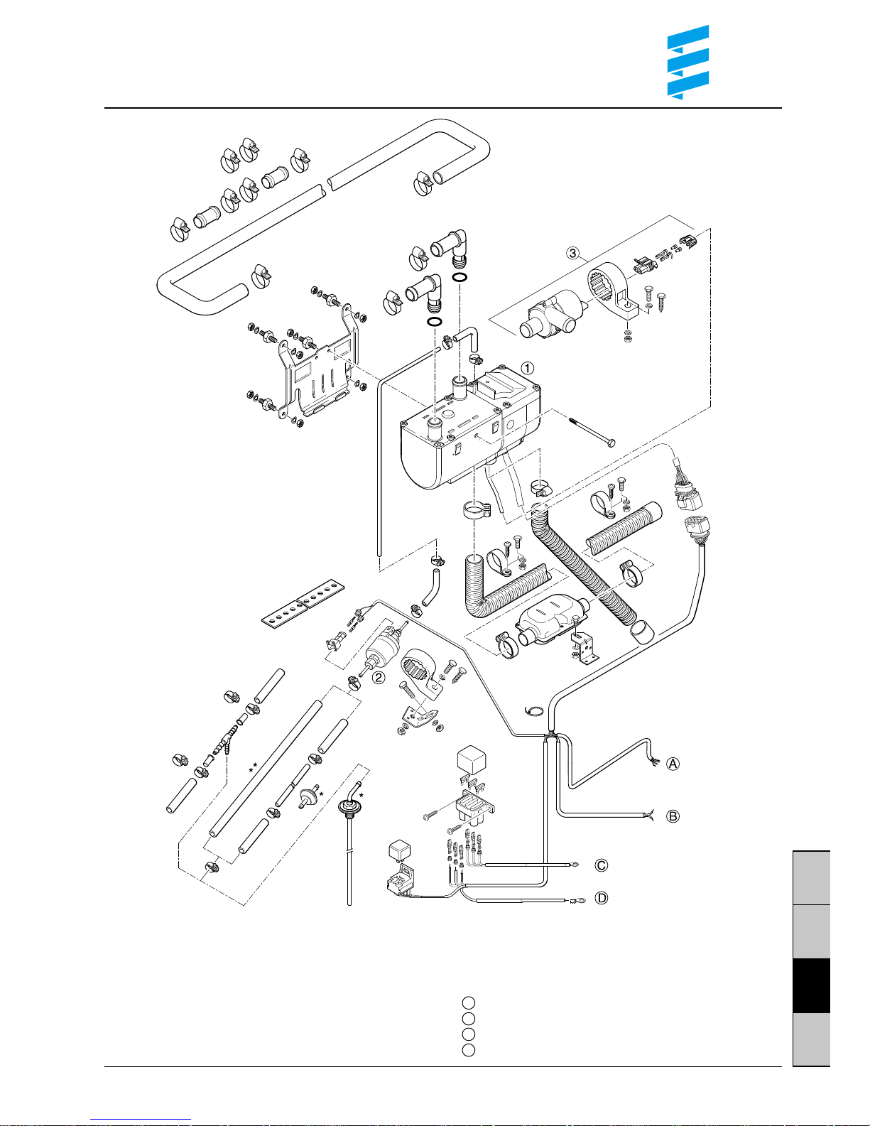
Scope of the delivery
햲
HYDRONIC
B 5 W S / D 5 W S
햳 Dosing pump
햴 Water pump
Parts without drawing number are included
in the universal mounting kit.
* Part only contained in universal mounting kit of
HYDRONIC
24 V.
** Part only contained in universal mounting kit of
HYDRONIC
12 V.
Cable harness “control elements”
Cable harness “fan control”
Positive cable
Negative cable
A
B
C
D
Page 4
4
D
S
GB
F
ATTENTION !
!
§
Safety instructions concerning the
installation and repair of the
HYDRONIC
Danger of burns and injury!
Before commencing any work on the
HYDRONIC
,
disconnect the vehicle battery.
Always switch off the
HYDRONIC
prior to any repair work
and allow hot components to cool down.
Statutory regulations concerning
the installation of the
HYDRONIC
• For installation in motor vehicles subject to the
Regulations authorizing the Use of Vehicles for Road
Traffic (StVZO), the air heater has been approved by
the German Federal Office for Motor Traffic in keeping
with the ‘General Design Certification’ (AGB) and the
official test symbol is marked on the type plate of the
heater.
HYDRONIC
B 5 W S S 288
HYDRONIC
D 5 W S S 274
• The mounting requirements associated with the General Design Certification (AGB) and further statutory
regulations have been printed in the corresponding
sections of these mounting instructions.
• When the air heater is installed in special vehicles, the
regulations governing such vehicles must be taken into
account (e.g. GGVS / TRS 003 / ADR / ADR 99 for
vehicles used to transport dangerous substances).
• The year in which the air heater was operated for the
first time must be permanently recorded on the type
plate. To this end, 3 different years have been printed
on the corresponding field of the type plate. The valid
year is to be identified by removing (detaching) those
two years which are not applicable.
• Heaters have to be installed in accordance with the
mounting instructions. The installation must be
checked by an officially approved specialist or
inspector for road traffic, a motor vehicle specialist or
an employee in accordance with paragraph 7.4 a of the
Annex to the StVZO, and must be certified on the
confirmation of acceptance included in the copy of the
general model approval (ABG) according to
a) § 20 StVZO in case of a type approval of vehicles;
b) § 32 StVZO in case of an individual approval;
c) § 19 StVZO in case of an appraisal.
For case c), the vehicle manufacturer, vehicle model
and vehicle identification number must also be
specified.
The validity of the model approval depends on this.
The confirmation of acceptance must be carried in
the vehicle.
• For vehicles not subject to the StVZO, it is necessary
to observe the specific regulations and mounting
instructions applicable to the given vehicle.
• The heater may only be installed or repaired – in case
of the heater being handed in for repair or guarantee
reasons – by a specialist workshop approved by the
manufacturer (service partner) in keeping with these
mounting instructions and possible special installation
recom-mendations.
• The information sticker ‘Switch off heater before
refuelling’ suppplied with the heater must be attached
in a suitable position on the vehicle (close to the fuel
filler neck).
Important instructions for
the installation and repair
of the
HYDRONIC
When mounting or repairing the heater, only original
accessories and original spare parts may be used.
Changes to the
HYDRONIC
or to components relevant to
the heating, the use of outside parts not approved by
Eberspächer as well as an installation or operation
differing from the statutory, safety and /or function relevant specifications contained in the mounting instructions and in the operating instructions are not permissible:
this applies in particular to the electric wiring (circuit
diagrams), the fuel supply, the combustion air and exhaust gas duct.
Fuel pipes and exhaust pipes must be safely fastened,
to avoid damage from vibrations (recommendation: at
intervals of approx. 50 cm).
Ensure that the insulation of electrical lines cannot be damaged due to abrasion, kinking, squeezing or by exposure
to heat.
Only the control elements provided and / or approved by
us, either on their own or in a given combination, may be
used to operate the
HYDRONIC
. The use of other control
elements may lead to malfunctions of the heater / heating
operation.
Non-compliance with the statutory, safety and / or
function relevant specifications leads to the lapse of the
General Design Certification (ABG) of the
HYDRONIC
and to the exclusion of guarantee and liability on the part
of the company J. Eberspächer GmbH & Co.
Please note!
• Further ‘Safety instructions concerning the installation
and repair of the
HYDRONIC
’ as well as ‘Important
instructions concerning the installation’ have been
printed directly in the corresponding sections of these
mounting instructions.
• The confirmation of acceptance has been enclosed
with the documents for the
HYDRONIC
.
Page 5
5
D
S
GB
F
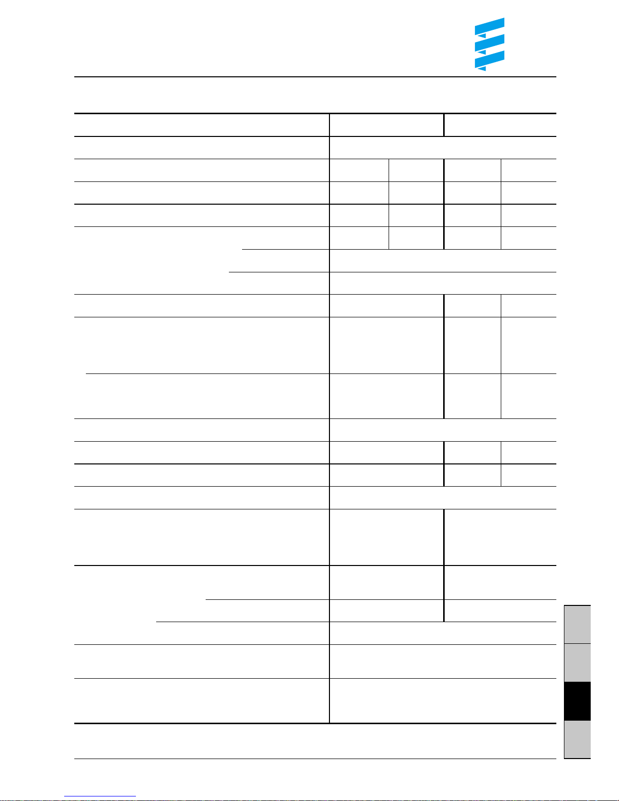
Technical data
Heater B 5 W S D 5 W S
Heating medium Water, glycol compounds
Heat flow settings Large Small Large Small
Heat flow (watt) 5000 1500 5000 2400
Fuel consumption (l/h) 0.69 0.20 0.62 0.27
Electrical input (watt) During operation 37 10 37 10
When starting 110
During after running 8
Rated voltage 12 V 12 V 24 V
Operating range
Lower voltage limit 10.2 V 10.2 V 20.4 V
An under-voltage protecting device in the controller
turns off the heater at approx. 10 V (after 20 seconds)
Upper voltage limit 16 V 16 V 32 V
An over-voltage protecting device in the controller
turns off the heater at approx. 16 V (after 20 seconds)
Permissible working pressure up to 2.5 bar excess pressure
Water throughput of water pump against 0.1 bar 800 l/h 800 l/h 950 l/h
Electric power consumption water pump 16 W 16 W 12 W
Min. water flow rate of heater 250 l/h
Fuel Commercial petrol Commercial diesel fuel
For “Fuel quality” and “Fuel at low temperatures” (to DIN 51600 (to DIN EN 590)
see Operating Instructions and DIN EN 228)
PME (acc. to DIN V 51606)
only at D 5 W S, 24 V
Permissible ambient temperature
Operation –
HYDRONIC
–40 °C to +80 °C –40 °C to +80 °C
Operation – Dosing pump –40 °C to +20 °C –40 °C to +80 °C
Storage –
HYDRONIC
/ Dosing pump –40 °C to +105 °C
Degree of radio interference suppression 5 for VHF / SW / MW
2 for LW
Weight
without water and add on pieces approx. 2.3 kg
including water pump and dosing pump approx. 2.9 kg
All technical data ± 10 %
Page 6
6
D
S
GB
F
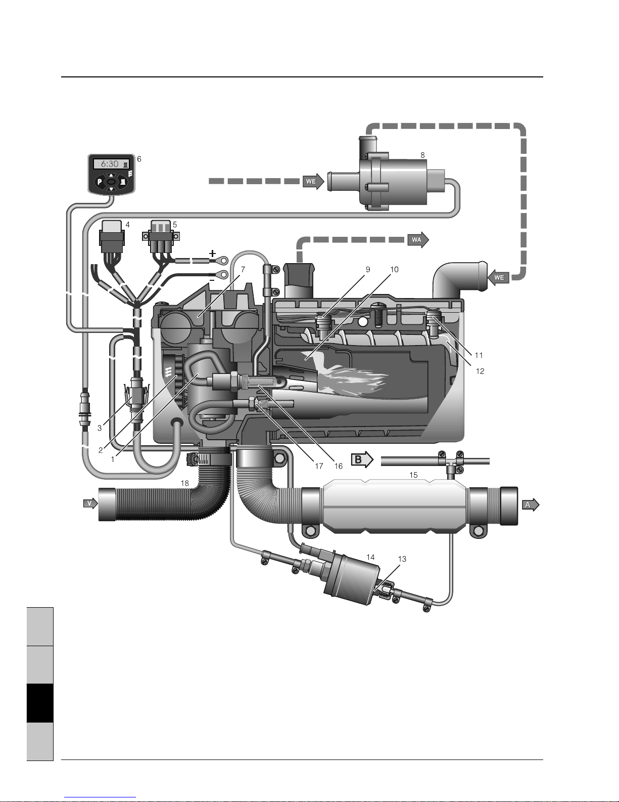
1 Electric motor
2 Controller
3 Intersection /
8-channel connector
4 Relay, vehicle fan
5 Main fuse / fuse holder
6 Module clock
7 Combustion air blower
8 Water pump
9 Temperature probe
A = Exhaust gas
B = Fuel
V = Combustion air
WA = Water outlet
WE = Water inlet
Sectional drawing (shown here is the
HYDRONIC
B 5 W S)
10 Combustion chamber
11 Overheating sensor
12 Heat exchanger
13 Cup strainer, built into dosing pump
14 Dosing pump
15 Exhaust piping with exhaust muffler
16 Glow plug
17 Flame sensor
18 Combustion air tube
from vehicle engine
to heat exchanger
Page 7
7
D
S
GB
F
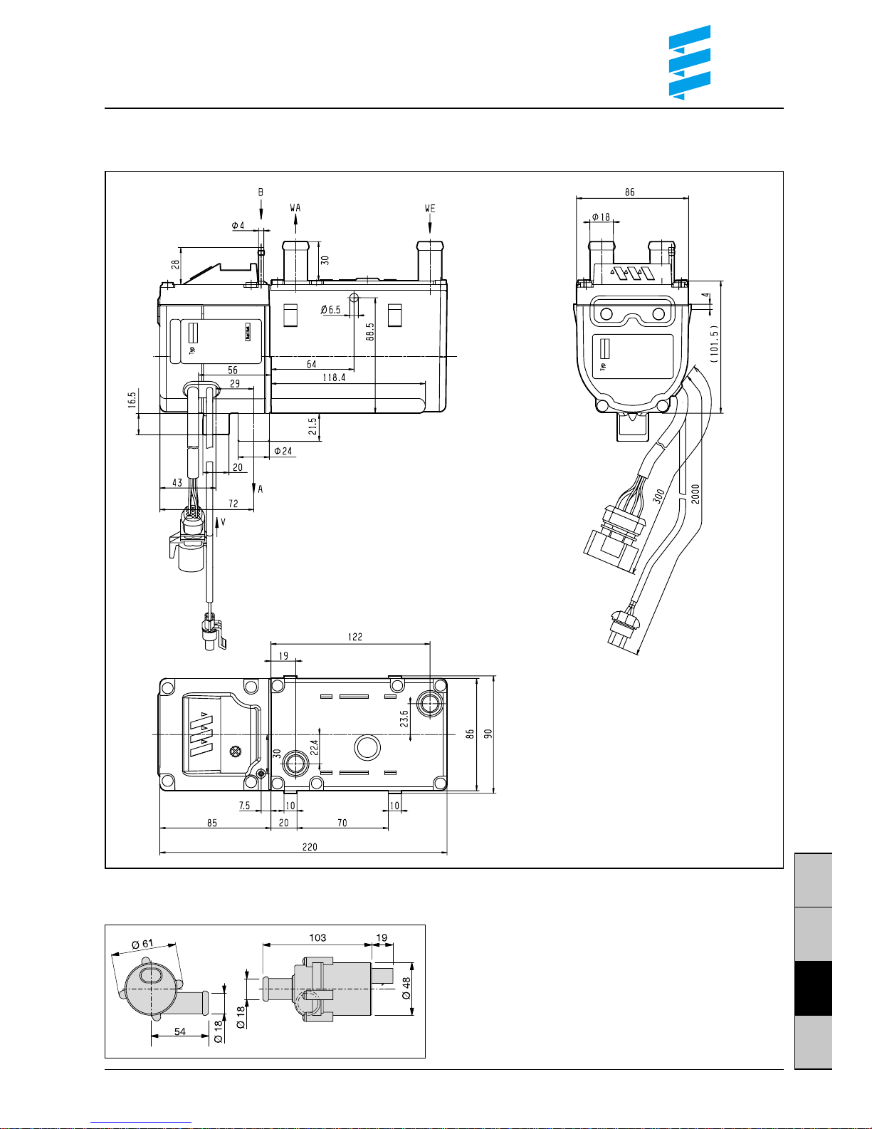
Principal dimensions
HYDRONIC
A = Exhaust gas
B = Fuel
V = Combustion air
WA = Water outlet
WE = Water inlet
Water pump
Page 8
8
D
S
GB
F
1
7
8
2
3
5
4
10
9
11
6
10
5
8
2
3
1
4
6
11
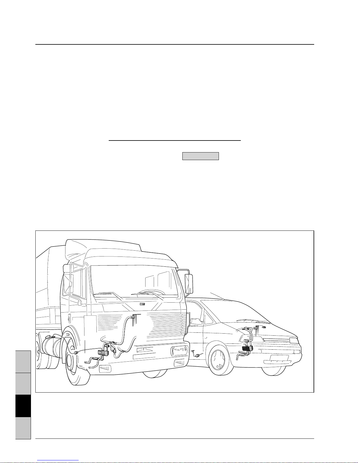
Mounting example
햲 Heater
햳 Exhaust piping with exhaust muffler
햴 Combustion air tube
햵 Water pump
햶 Check valve
햷 T-piece (water circulation system)
햸 Thermostat
햹 Vehicle’s heat exchanger
with fan
햺 Tank connection / T-piece (fuel)
햻 Dosing pump
햽 Module clock
Mounting the heater and water pump
Point of installation is the engine compartment. Mount
the heater as deeply as possible so that heat exchanger and water pump can deaerate automatically.
Observe permissible mounting positions as well as
operating and storage temperatures.
Mounting instructions
The heater, in conjunction with the vehicle’s heating
system, is used to preheat the engine, to heat the
passenger compartment and to defrost the window
panes.
The heater is connected to the vehicle’s coolingwater circulation, electrical system and fuel system.
If it is wired accordingly, the heater will operate as
additional heater, thereby increasing the heat flow of
the vehicle’s own heating – in particular in the case
of motors with optimised fuel consumption – to a
comfortable level.
(It is not permissible) to install the heater inside
vehicles used for the transport of hazardous substances, inside the passenger compartment, driver’s
cab, working cabin, seating compartment (troop
carrier, mini busses, motorbusses*) and generally in
rooms used by people is not permissible. When
installing the heater in special-purpose vehicles
valid regulations have to be complied with.
* Vehicles with more than 9 seats.
Please note!
The proposed points of installation given in these
mounting instructions are examples.
Other points of installation are also permissible
if they comply with the installation requirements
specified in these mounting instructions.
Further information concerning the installation
(e.g. for boats and ships) may be obtained from
the manufacturer on request.
Page 9
9
D
S
GB
F
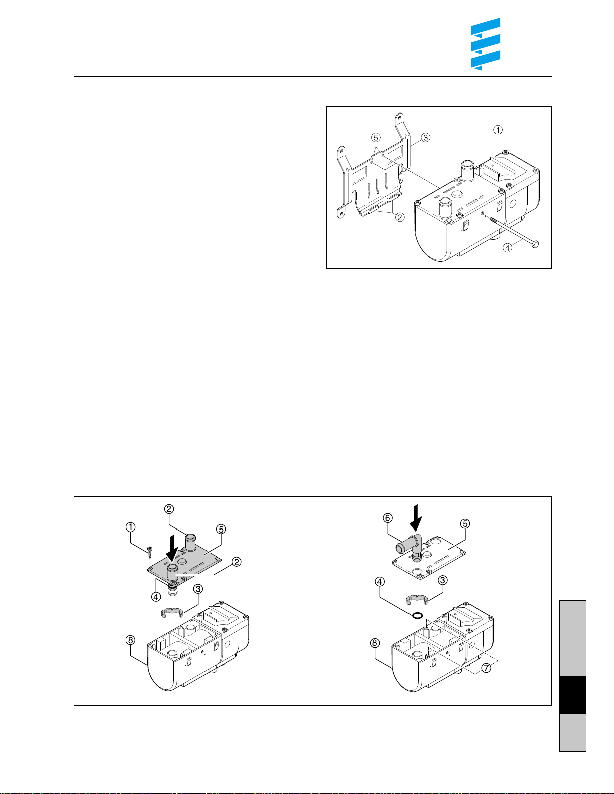
Mounting the heater onto the holder
• Insert heater in retaining lugs on holder.
• Screw heater onto holder with fastening screw
(6
+0.5
Nm).
Note:
Depending on the installation space, it is possible
to move the heater inside the holder and to secure it
with screws in one of the two fastening threads.
햲
HYDRONIC
햳 Retaining lugs
햴 Holder
햵 Fastening screw
햶 Fastening threads
Installation of the angular connection piece
HYDRONIC
B 5 W S and D 5 W S are supplied with
straight connection pieces. Depending on the
installation conditions, it may be necessary to install
angular connection pieces.
• Unscrew fastening screws on lid and remove lid.
• Push straight connection piece downwards.
• Undo serrated ring and remove O-ring.
• Pull connection piece out of lid.
• Push angular connection piece into lid, insert new
O-ring into the groove provided for that purpose
and grease sparingly.
• Mount serrated ring on angular connection piece,
twist connection piece depending on the installation
position and insert into the lid’s toothed ring.
• Screw lid back onto the casing with four screws –
torque 4 Nm.
Should the angular connection piece cover the
previous screw opening, the adjacent screw hole
has to be used.
This must be done as follows:
• A thread has to be tapped beforehand in the hole
of the
HYDRONIC
’s aluminium casing by
screwing one of the tapping screws into the hole
and unscrewing it again.
• Put on lid and screw in all four screws – torque
4.5 Nm.
Note:
The threads have to be tapped prior to mounting
the lid.
햲 Fastening screws
햳 Straight connection
햴 Serrated ring
햵 O-ring
햶 Lid
햷 Angular connection
햸 Hole
햹
HYDRONIC
Page 10

10
D
S
GB
F
Water pump
Normal position horizontal with permissible swivel
range.
Please note!
The outlet nozzle must be pointing 5° upward,
as shown in the drawing.
Permissible mounting positions
The heater and the water pump are to be installed
in the standard position. Depending on prevailing
installation conditions, the heater and the water
pump can be tilted as shown in the drawing.
or
The maximum permissible deviations from the normal position are indicated in the drawing.
Please consult the manufacturer if wider deviations
are necessary.
HYDRONIC
Normal position horizontal (exhaust pipe to the
bottom) with permissible swivel range.
Type plate
The type plate must be clearly visible after the
heater has been installed. If necessary, a second
type plate (duplicate) with the same details as the
original one can be mounted at a clearly visible
point on the air heater or a cover in front of the air
heater.
A second type plate is not necessary if the original
type plate is clearly visible under a cover that can
be removed without having to use tools. The type
plate is mounted on the basic unit.
Page 11

11
D
S
GB
F
Connection to the cooling water circuit
A careful deaeration of the water cycle (including
heater) after installation of the heater is necessary for
the perfect functioning of the device:
1. Fill heater and water hoses with coolant after installation, but before connection to the cooling water
cycle. The vent screw must remain open during
filling. If water issues from the opening of the vent
screw, the heater is deaerated. Close the vent
screw again.
2. Afterwards, the entire cooling system must be
deaerated to remove any bubbles in accordance
with the engine manufacturer’s instructions.
The pressure in the water cycle must be limited
to max. 2.5 bar excess pressure inside a pressure
control valve (e.g. radiator filler cap).
Attention!
During operation with auxiliary heating, the vehicle’s
heating valve must always be kept completely open
either electrically or mechanically.
Recommendation:
Use switches with final position contact (“break
contact”) for all heating cycles.
Please note!
If the heater is integrated in a vehicle engine’s cooling
system, it is part of this cooling system.
The following points thus need to be taken into account:
• The heater must always be mounted beneath the
min. cooling water level (coolant recovery bottle,
radiator, vehicle heat exchanger) in such a manner
that it works in the direction of flow of the engine
cooling cycle. After installation, the entire cooling
system including the heater must be deaerated to
remove any bubbles in accordance with the engine
manufacturer’s instructions. This also applies after
every interference with the cooling water system
(repair, exchange of cooling water). All water connections (clamps) have to be perfectly tightened
and retightened after the vehicle has been driven
for 2 hours or approx. 100 km. Any water-carrying
pipes must be protected against chafing and excessive temperatures (radiant heat from exhaust
pipes). To prevent corrosion, the cooling water must
contain at least 10% antifreeze all the year round.
The coolant must contain sufficient antifreeze for low
temperatures.
• Operating the heater with frozen coolant is dangerous and thus inadmissable.
When refilling coolant, only use the one authorized by
the vehicle manufacturer. Compare the vehicle’s
operating instructions. Mixing it with unauthorized
coolant may lead to damage to the engine and heater.
Before remounting a heater into another vehicle, rinse
all water carrying parts of the heater with clear water.
Page 12

12
D
S
GB
F
5
2
1
4
3
2. Inserting the check valve into the inflow line
Cut open the inflow line running from the vehicle
engine to the heat exchanger and insert the check
valve.
Insert the heater and the water pump into the water
circulation system as shown in the drawing.
Check valve Ø 18 mm – Order No. 254 00 070
Check valve Ø 20 mm – Order No. 254 00 074
Characteristic heating curve as for water cycle “1”
Advantage:
No loss of efficacy of engine heating with the stationary heating switched off.
햲 Heater
햳 Water pump
햴 Check valve
햵 Vehicle’s heat exchanger
햶 Vehicle engine
4
2
1
3
햲 Heater
햳 Water pump
햴 Vehicle’s heat exchanger
햵 Vehicle engine
There are several possibilities:
1. Inserting heater into inflow line –
this arrangement is the simplest one
Cut open the inflow line running from the vehicle
engine to the heat exchanger and insert the heater
and the water pump.
Characteristic heating curve:
With the stationary heating switched on, the heat is
first fed to the vehicle engine. After the cooling water
temperature has reached approx. 30 °C, the heat is
also fed to the passenger compartment, depending
on the fan position selected.
Page 13

13
D
S
GB
F
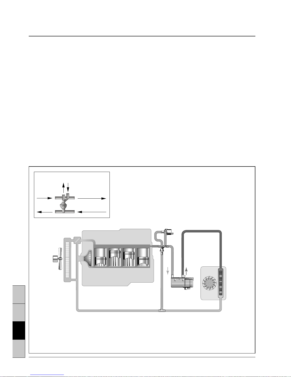
3. Integrating the deluxe installation kit
into the water circulation system
Deluxe installation kit, Order No. 24 0132 00 00 00
Cut open the inflow line running from the vehicle
engine to the heat exchanger and insert the check
valve.
Cut open the return line running from the heat
exchanger to the vehicle engine and insert the
T-piece. Insert the heater, thermostat and water
pump into the water circulation system as shown
in the drawing.
Characteristic heating curve:
First, up to a cooling water temperature of approx.
70 °C the heat of the auxiliary heating is only fed to
the passenger compartment = small cycle, fast heating up. If the cooling water temperature continues to
rise, the thermostat gradually changes over to the
large cycle = additional preheating of engine (full
change-over is reached at 75 °C).
Please note!
Execute connections 1, 2 and 3 as described in
the drawing.
7
2
1
6
3
4
5
t<70 °C = 3 closed
2 open
t>75 °C = 3 open
2 closed
Thermostat, Ø 18 mm
(always open)
햲 Heater
햳 Water pump
햴 Check valve
햵 Thermostat
햶 T-piece
햷 Vehicle’s heat exchanger
햸 Vehicle engine
Page 14
14
D
S
GB
F
6
1
5
2
3
4
4. Water cycle with combination valve
Mounting the combination valve – 5 connections
If the water flow pipe and water return pipe from the
vehicle engine to the heat exchanger in the engine
compartment have been spaced apart, the combination valve with 5 connections and one T-piece have
to be used.
Cut open the inflow line running from the vehicle
engine to the heat exchanger and insert the combination valve.
Cut open the return line running from the heat exchanger to the vehicle engine and insert the T-piece.
Mounting the combination valve – 6 connections
If the water flow pipe and water return pipe from the
vehicle engine to the heat exchanger in the engine
compartment have been installed parallel to each
other, the combination valve with 6 connections
(without T-piece) may be used.
Cut open the inflow and return lines running from
the vehicle engine to the heat exchanger and insert
the combination valve.
Combination valve with 5 connections:
Order No. 330 00 177
and additional
T-piece Ø 20 for return line:
Order No. 20 1673 80 11 00
Combination valve with 6 connections:
Order No. 330 00 176
Characteristic heating curve:
With the stationary heating switched on, the heat is
exclusively fed to the passenger compartment =
small cycle, fast heating up.
Once the vehicle engine is put into operation – at low
speed – a part of the heat is fed to the vehicle engine
(partial cycle) which leads to a shortening of the
vehicle engine’s warm-up period.
At increased engine speeds (> 2000 rpm), the entire
heat is distributed to the passenger compartment and
vehicle engine = large cycle, auxiliary heating function, further shortening of the warm-up period.
햲 Heater
햳 Water pump
햴 Combination valve (5 connections)
햵 T-piece
햶 Vehicle’s heat exchanger
햷 Vehicle engine
Combination valve (6 connections)
HYDRONIC
from vehicle
engine
to vehicle
engine
to vehicle
heat exchanger
from vehicle
heat exchanger
Page 15

15
D
S
GB
F
Conducting the combustion air / exhaust gas
Conducting the combustion air
The combustion air must be drawn in from the outside (not from the passenger compartment
or boot).
As described in these mounting instructions, the
heater is installed inside the engine compartment. If
the air intake fitting for the combustion air is situated
in an area where the combustion air does not reach
temperatures exceeding 25 °C, and where neither
road spray nor dust / dirt are to be expected, the
combustion air intake is already complete. If this is
not the case, a flexible hose with an inner diameter of
20 mm and up to 1.5 m long has to be connected to
take the combustion air from an area complying with
this condition.
The inlet opening of the combustion air pipe may in
that case not be built in against the air stream and
must be installed in such a manner that it cannot be
clogged by dirt and snow and that penetrated water
may run off.
Push on the end sleeves so that a 16 mm diameter
ball cannot be inserted (requirement of StVZO
“Technical Demands Expected of Heaters”).
Conducting the exhaust gas
The items supplied include a flexible exhaust hose
with an inner diameter of 24 mm and 1000 mm long.
It must be cut apart at a suitable place and the exhaust silencer inserted (compare diagram on page 3);
the exhaust tailpipe 햶 should be much shorter than
the exhaust pipe 햴. If necessary, the exhaust hose
pipe may be shortened or extended up to a maximum
length of 2 m.
The exhaust gas pipe must not protrude beyond the
external limits of the vehicle.
The exhaust pipe must either slope downwards
slightly, or a 5 mm diam. hole must be drilled into
the lowest point of the pipe to allow condensate to
drain off.
Always fasten the silencer; longer exhaust pipes must
always be fastened at intervals of approx. 50 cm.
bis 1,5m
bis 2m
1
2
4
35
up to 1.5 m
up to 2 m
햲 Heater
햳 Combustion air hose
햴 Exhaust gas pipe
햵 Exhaust gas silencer
햶 Exhaust tail pipe
Arrange the exhaust gas outlet in such a manner
that the exhaust gas cannot be immediately drawn
in again.
The exhaust gas outlet must lead out into the open air.
The exhaust gas pipe must be arranged in such a
manner that exhaust gas cannot enter the vehicle,
be drawn in by the vehicle's fan or by the heater
fan
1)
, nor must it impair the function of vital vehicle
parts in any way (ensure that an adequate distance
is maintained).
Run the exhaust gas pipe in such a manner that
it cannot be clogged up by dirt, snow or water
(draining hole). Do not position the outlet opening of
the exhaust gas against the air stream.
An end sleeve crossed with a web must be mounted
on the end of the exhaust gas pipe so that a 16 mm
diameter ball cannot be inserted (requirement of
StVZO “Technical Demands Expected of Heaters”).
1)
This requirement is considered to be fulfilled when
the end of the exhaust gas pipe is run upwards or
to the side, or when the exhaust gas pipe passes
underneath the vehicle floor to the vicinity of the
side or rear limits of the driver's cab or the passenger compartment.
!
Danger of poisoning and burns!
Every combustion process creates exhaust gas
which contains toxic constituents; for this reason
and due to the high temperatures occurring, the
exhaust gas duct needs to be absolutely carried out
in accordance with the specifications of these
mounting instructions.
During heating operation, avoid any work in the area
of the exhaust gas duct.
In such a case, switch off the
HYDRONIC
beforehand and wait until all parts have completely
cooled down.
If necessary, wear protective gloves.
Page 16

16
D
S
GB
F
a
8
b
Fuel supply
Operation with bio-diesel (PME) –
HYDRONIC
D 5 W S - 24 V
HYDRONIC
D 5 W S - 24 V is certified for operation
with bio-diesel as per DIN V 51606 in free-flowing
state (decreases at temperatures under 0 °C).
1. Tapping fuel with the T-piece from the fuel
supply line
Precondition:
Fuel lines must be tight.
A maximum preliminary pressure of 0.3 bar can
arise in the fuel lines in any operating mode.
Please note!
Deviations from the instructions given here are
impermissible, otherwise functional disorders
can arise.
Tapping fuel from the supply line downstream of the
delivery pump is prohibited in cars, since pressures
of up to 10 bars can occur.
Before the air heater is turned on it is first necessary
to start up the vehicle's engine so that the fuel lines
can be filled.
To engine
mechanical fuel pump
or injection pump
햲 Inflow line running from tank fitting to engine –
insert T-piece into inflow line upstream of delivery
pump
햳 Return line running
햴 Dosing pump
햵 T-piece
햶 Fuel filter – only required if fuel is contaminated
햷 Fuel hose, 5 x 3 (inner diameter = Ø 5 mm) –
HYDRONIC
B 5 W S only
햸 Fuel pipe, 6 x 2 (inner diameter = Ø 2 mm)
햹 Fuel pipe, 4 x 1,25
(inner diameter = Ø 1,5 mm)
햺 Fuel hose, 5 x 3 (inner diameter = Ø 5 mm),
approx. 50 mm long
햻 Fuel hose, 3,5 x 3 (inner diameter = Ø 3,5 mm),
approx. 50 mm long
Permissible line lengths
Suction side
a = max. 2 m
Pressure side
b = max. 4 m for petrol
b = max. 6 m for diesel
!
Danger of fire and explosion!
Poisonous fumes!
Caution when handling fuel. Before filling up and
when working on the fuel supply, switch off the
vehicle’s engine and the
HYDRONIC
.
Avoid open fire when handling fuel.
Do not smoke; this also applies there where
the presence of fuel is only noticeable on account
of its characteristic smell.
Do not inhale petrol fumes.
Page 17

17
D
S
GB
F
a
10
b
2. Tapping fuel with rising tank connection
installed in the vehicle tank or in the tank
fitting
If it is not possible to install a separate rising pipe in
cars with fuel injected engines the return line can be
tapped by means of a T-piece.
Condition:
• No valve may be installed in the return line
in the tank.
• The pressure inside the return line may reach
a max. of 2 bar. In case of pressures above 0.3
and up to 2 bar a pressure reducer (add-on part,
order No. 20 1645 89 30 00) must be installed
in front of the dosing pump.
Permissible line lengths
Suction side
a = max. 2 m
Pressure side
b = max. 4 m for petrol
b = max. 6 m for diesel
햲 Tank connection for metal tank,
inner diameter = Ø 2 mm,
external diameter = Ø 6 mm,
order no. 25 1226 89 50 00
햳 Tank connection for tank fitting,
inner diameter = Ø 2 mm,
external diameter = Ø 4 mm,
order no. 20 1645 89 35 00
햴 Dosing pump
햵 Fuel filter – only required if fuel is contaminated
햶 Fuel hose, 5 x 3 (inner diameter = Ø 5 mm) –
HYDRONIC
B 5 W S only
햷 Fuel pipe, 6 x 2 (inner diameter = Ø 2 mm)
햸 Fuel pipe, 4 x 1 (inner diameter = Ø 2 mm)
햹 Fuel hose, 3,5 x 3 (inner diameter = Ø 3,5 mm),
approx. 50 mm long
햺 Fuel hose, 5 x 3 (inner diameter = Ø 5 mm),
approx. 50 mm long
햻 Fuel pipe, 4 x 1,25 (inner diameter = Ø 1,5 mm)
햽 Connecting piece, external diameter = 4 mm
Page 18

18
D
S
GB
F
Mounting position of the dosing pump
Permissible suction and pressure level
of the dosing pump
햲 Dosing pump
햳 Maximum fuel level
햴 Minimum fuel level
햵 Connection on the heater
Mounting position of the dosing pump
Mount the dosing pump in the vehicle with the pres-
sure side rising by at least 15° and maximum 90°.
If possible the fuel lines from the dosing pump to
the heater should rise continuously.
Permissible suction and pressure level
Pressure level from the vehicle's tank to the dosing
pump:
a = max. 3000 mm
Suction level with a pressureless vehicle tank:
b = max. 500 mm for petrol
b = max. 1000 mm for diesel
Please note: Check the tank venting.
Suction level with a vehicle tank in which fuel tapping produces a vacuum (valve with 0.03 bar in the
tank closure):
b = max. 150 mm for petrol
b = max. 450 mm for diesel
Pressure level from the dosing pump to the heater:
c = max. 2000 mm
pressure side
Page 19

19
D
S
GB
F
• Always fasten the fuel pipes at intervals of approx.
50 cm.
• Always use a rubber hose to connect the fuel
branching piece – never use a plastic pipe.
• The fuel pipe must always be butt-jointed where
there is a connection between fuel pipes and
a fuel hose (see Drawing A).
• When incorporating a T-piece ensure that the
mounting position indicated on Drawing B is
observed.
•§§ 45 and 46 of StVZO also apply correspondingly to the fuel lines and additional heater tanks.
Please note!
• A pressure reducer (Order No. 20 1645 89 30 00)
or a separate tank connection (see page 13) must
be used if the pressure in the fuel line exceeds
0.2 bar to maximum 2.0 bar.
• A separate tank connection if the pressure in
the fuel line exceeds 2.0 bar or if the return line
incorporates a check valve.
• Fuel tapping in a car after the conveying pump
is prohibited!
• Fuel hoses and pipes must be cut to length with
a sharp knife; the cut-off point must not be dented
and must be burr-free.
• Protect the fuel line, filter and dosing pump
from impermissible heat, and do not mount in
the vicinity of silencers and exhaust gas pipes.
Drawing A: Drawing B:
correct
incorrect
Page 20

20
D
S
GB
F
Circuit diagram
HYDRONIC
B 5 W S / D 5 W S – 12 volt
Parts list
1.1 Burner motor
1.2 Glow plug
1.5 Overheating sensor
1.12 Flame sensor
1.13 Temperature probe
2.1 Controller
2.2 Dosing pump
2.5.7 Relay, vehicle fan
2.7 Main fuse 20 A
2.7.1 Fuse, actuation 5 A
2.7.5 Fuse, vehicle fan 25 A
2.12 Water pump
5.1 Battery
5.1.2 Fuse strip in vehicle
5.9.1 Switch, vehicle fan
5.10 Vehicle fan
Cable colours
sw = black
ws = white
rt = red
ge = yellow
gn = green
vi = violet
br = brown
gr = grey
bl = blew
li = purple
a) for auxiliary heating option connect to D+
f) cut open wire
g) only with petrol
h) only with diesel
k) switch (auxiliary heating, e.g. outside temperature
< 5 °C or change-over switch for summer / winter)
Length ‘plus’ + length ‘minus’:
< 5 m: cross section 4 mm
2
> 5 m < 8 m: cross section 6 mm
2
Cable ends that are not being used must be isolated.
Plug and socket case are shown from the cable entry
side.
20 1777 00 96 01 B
Page 21

21
D
S
GB
F
20 1777 00 97 01 A
Parts list
2.15.9 Sensor, outside temperature
3.1.9 Change-over switch ‘heating / ventilating’
3.1.16 Key button, radio remote control
3.2.6 Timer, mini-clock
3.2.9 Timer, module clock
3.2.12 Timer, mini-clock
3.3.6 TP 41i radio remote control (receiver)
b) Connect to terminal +15 if heating operation
> 2 hrs (with the ignition switched on) is desired
c) Lighting terminal 58
d) Stationary ventilation (optional)
e) External switch ON / OFF (optional)
i) Connection radio module receiver TP 4i
Length ‘plus’ + length ‘minus’:
< 5 m: cross section 4 mm
2
> 5 m < 8 m: cross section 6 mm
2
Cable ends that are not being used must be
insulated.
Plug and socket case are shown from the cable
entry side.
Please note!
For vehicles with automatic heating or airconditioning,
vehicle fan control must be in accordance with our
vehicle-related workshop information. If no workshop
information is available, the vehicle manufacturer’s
instructions with regard to the connection and / or point
of intersection for the fan control must be adhered to.
Cable colours
sw = black
ws = white
rt = red
ge = yellow
gn = green
Circuit diagram
Control elements – 12 volt
vi = violet
br = brown
gr = grey
bl = blew
li = purple
Page 22

22
D
S
GB
F
25 2147 00 96 01Parts list
1.1 Burner motor
1.2 Glow plug
1.5 Overheating sensor
1.12 Flame sensor
1.13 Temperature probe
2.1 Controller
2.2 Dosing pump
2.5.7 Relay, vehicle fan
2.7 Main fuse 15 A
2.7.1 Fuse, actuation 5 A
2.7.5 Fuse, vehicle fan 25 A
2.12 Water pump
5.1 Battery
5.1.2 Fuse strip in vehicle
5.9.1 Switch, vehicle fan
5.10 Vehicle fan
Cable colours
sw = black
ws = white
rt = red
ge = yellow
gn = green
vi = violet
br = brown
gr = grey
bl = blew
li = purple
f) cut open wire
Length ‘plus’ + length ‘minus’:
< 5 m: cross section 4 mm
2
> 5 m < 8 m: cross section 6 mm
2
Cable ends that are not being used
must be isolated.
Plug and socket case are shown
from the cable entry side.
Please note!
The vehicle ventilator runs immediately
after the heater has been started.
Circuit diagram
HYDRONIC
D 5 W S – 24 volt
Page 23

23
D
S
GB
F
Circuit diagram
Control elements – 24 volt
Please note!
For vehicles with automatic heating or airconditioning,
vehicle fan control must be in accordance with our
vehicle-related workshop information. If no workshop
information is available, the vehicle manufacturer’s
instructions with regard to the connection and / or
point of intersection for the fan control must be
adhered to.
Cable colours
sw = black
ws = white
rt = red
ge = yellow
gn = green
vi = violet
br = brown
gr = grey
bl = blew
li = purple
Parts list
2.15.9 Sensor, outside temperature
3.2.9 Timer, module clock, TRS
3.2.12 Timer, mini-clock
b) Connect to terminal +15 if heating operation
c) Lighting terminal 58
e) External switch ON / OFF (optional)
i) Connection radio module receiver
Length ‘plus’ + length ‘minus’:
< 5 m: cross section 4 mm
2
> 5 m < 8 m: cross section 6 mm
2
Cable ends that are not being used
must be insulated.
Plug and socket case are shown
from the cable entry side.
Page 24

24
D
S
GB
F
25 2147 00 97 01 C
Cable colours
sw = black
ws = white
rt = red
ge = yellow
gn = green
vi = violet
br = brown
gr = grey
bl = blew
li = purple
Circuit diagram
HYDRONIC
D 5 W S – 24 volt, GGVS / TRS 003 / ADR / ADR 99
Page 25

25
D
S
GB
F
Circuit diagram
Control elements – 24 volt, GGVS / TRS 003 / ADR / ADR 99
Parts list
1.1 Burner motor
1.2 Glow plug
1.5 Overheating sensor
1.12 Flame sensor
1.13 Temperature probe
2.1 Controller
2.2 Dosing pump
2.5.7 Relay, vehicle fan
2.7 Main fuse 15 A
2.7.1 Fuse, actuation 5 A
2.7.5 Fuse, vehicle fan 25 A
2.12 Water pump
3.2.9 Timer, module clock, TRS
5.1 Battery
5.1.2 Fuse strip in vehicle
5.2.1 Battery operating switch m)
(operation e.g. controlled
via ignition lock)
5.2.2 Battery separating switch m)
(Emergency-shutdown function in the case
of GGVS / TRS 003 / ADR / ADR 99)
5.3 Accessory drive HA+
5.3.1 Switch auxiliary drive
5.5 Generator D+
5.9.1 Switch, vehicle fan
5.10 Vehicle fan
b) Connect to terminal +15
c) Lighting terminal 58
f) Cut open wire
g) Insulate cable and tie back
m) if only one control element is used for items 5.2.1
and 5.2.2, it must be ensured that, if the function
‘opening of battery separating switch’ is
actuated (emergency shutdown-function in the
case of GGVS / TRS 003 / ADR / ADR 99) and
similar), the switch always breaks contact
without delay (without consideration for the
heater mode) and breaks all of the heater’s
circuits from the battery.
Length ‘plus’ + length ‘minus’:
< 5 m: cross section 4 mm
2
> 5 m < 8 m: cross section 6 mm
2
Cable ends that are not being used
must be isolated.
Plug and socket case are shown
from the cable entry side.
Please note!
The cables drawn in as dashed lines have to be
additionally laid and connected. Prior to doing so,
disconnect the wire harness at the positions marked
with f). Cable seals and push-on contacts for the
connector B1 and the ventilator relay are contained
in the installation kit.
The vehicle ventilator runs immediately after the
heater has been started.
For vehicles with automatic heating or airconditioning,
vehicle fan control must be in accordance with our
vehicle-related workshop information. If no workshop
information is available, the vehicle manufacturer’s
instructions with regard to the connection and / or
point of intersection for the fan control must be
adhered to.
Page 26

26
D
S
GB
F
Function
Depending on the wiring, the heater can be operated
as purely stationary heater or as combined stationary
and auxiliary heater to compensate for an insufficient
output of heat by the vehicle engine.
Stationary heating operation
Switching on
The pilot lamp in the control unit lights up when the
heater is switched on (switch, timer ...). The water pump
starts and after a fixed programme with prerinsing and
preheating, combustion air fan, glow plug and fuel dosing pump set combustion going. Once a stable flame
has formed, the glow plug is switched off by a timer.
Heating operation
Depending on the heat requirement, the heater may
be adjusted to the following levels:
“LARGE” or “SMALL”.
The temperature thresholds have been fixed programmed in the electronic control device. If the heat
requirement at level “SMALL” is so low that the cool-
ing water temperature reaches 85 °C, the device
goes into the control interval. This is followed by the
fan continuing to run for approx. 130 seconds. The
pilot lamp also lights up during the control interval
and the water pump continues to run up to the next
controlled start.
Check the following points in the event of faults:
The heater does not start when it is switched on:
Turn-off the heater and then switch it on again,
but not more than twice in succession.
If the heater still does not start:
Is there fuel in the tank?
Has the fuse blown?
Are all electrical lines and connections ok?
Is the combustion-air duct or exhaust-gas duct
blocked?
Conduct a diagnostic test with the JE diagnostic
instrument or the module clock as described in
“Trouble Shooting and Repairs Instructions”
for the
HYDRONIC
B 5 W S / D 5 W S.
Page 27

27
D
S
GB
F
Controls and safety devices
• If the heater does not ignite within 90 seconds
after fuel pumping has started, then the start
procedure must be repeated in the described
manner.
A fault shut-down is effected if the air heater once
again fails to ignite after 90 seconds of fuel
pumping.
After an excessive number of unsuccessful
attempts to start the heater, the control will be
locked*.
• A renewed start must be completed if the flame
extinguishes itself during operation. A fault shutdown is effected if the air heater fails to ignite
within 90 seconds after renewed fuel pumping or
if it does ignite but then extinguishes itself within
the next 15 minutes.
It is possible to override a fault shut-down by
briefly switching the heater off and then on again.
Do not repeat this more than twice
in succession!
• In case of overheating (lack of water, badly vented
cooling water cycle), the overheating sensor will
respond, the fuel supply will be interrupted and a
fault shut-down is effected. Once the cause of
overheating has been eliminated, the device can
be restarted by switching it off and on again
(condition: device has sufficiently cooled down,
cooling water temperature < 70 °C).
After an excessive number of switching-offs due
to overheating the control will be locked*.
• A fault shut-down is effected when the upper
or lower voltage limit is reached.
• The air heater will not start if the glow plug is
defective or if the electrical line to the dosing
pump is interrupted.
• The rotating speed of the fan motor is continuously
monitored. A fault shut-down is effected after
60 seconds if the fan motor does not start, if it is
blocked or if the rotating speed drops below 40 %
of the desired speed.
* Reading off errors and cancelling of locking:
1. by means of the built-in module clock
(3.2.9 in the circuit diagram)
2. if other control elements have been built in,
by means of connecting the diagnostic device
22 1512 89 00 00 instead of these other control
elements.
Operation and list of errors see operating instructions
for the diagnostic device and / or the trouble-shooting
and repair instructions
HYDRONIC
B 5 W S /
D 5 W S.
Stationary ventilation with change-over switch
‘heating / ventilating’
Stationary ventilation means that it is possible to
directly control the vehicle fan by means of the heating device preselector or – even more effectively – via
the radio remote control TP4i / TP41i, thus bypassing
the heating operation. This serves the purpose of
ventilating the passenger compartment shortly before
departure with fresh air as it often heats up considerably during summer time (separate wiring).
GGVS / TRS 003 / ADR / ADR 99 –
mode of operation
Please note!
The
HYDRONIC
D 5 W S – 24 volt is suitable and
certified for installation in vehicles used to transport
dangerous substances according to the regulations
in accordance with GGVS / TRS 003 / ADR / ADR 99
(detailed information is contained in an information
sheet with print no. 25 2069 95 13 50).
Forced cut-off in GGVS / TRS 003 / ADR / ADR 99
mode
When vehicles are used to transport dangerous
substances (e.g. road tankers), the heater must be
switched off before entering the hazardous area
(refinery, petrol station, etc.). If this is not observed,
then the heater will automatically shut-down when:
– The vehicle's engine is turned off.
– An accessory unit is switch on (e.g. auxiliary drive
for the unloading pump).
– A vehicle door is opened (TMD regulation; only in
France).
After shut-down the fan will continue to run for max.
40 seconds.
Please note!
• To prevent corrosion, the coolant must contain
at least 10 % antifreeze all the year round.
• The controller must be protected while electric
welding work is being completed on the
vehicle by disconnecting the “plus” pole from
the battery and connecting it to the chassis.
 Loading...