

Eberspächer HYDRONIC B4WSC, HYDRONIC B5WSC Technical Manual
1
D
S
GB
F
Documentation
for installation*
Eberspächer ®
Subject to change
B 4 W SC and B 5 W SC
Technical Description
Mounting Instructions
J. Eberspächer
GmbH & Co. KG
Eberspächerstr. 24
D - 73730 Esslingen
Telefon (zentral)
(0711) 939 - 00
Telefax
(0711) 939 - 0500
www.eberspaecher.com
Contents Page
Items supplied .......................................................... 2, 3
Control elements, optional ........................................ 2
Government regulations and
safety instructions concerning installation .............. 4
Technical data ........................................................... 5
Sectional drawing ..................................................... 6
Principal dimensions / Installation ........................... 7, 8
Mounting instructions / mounting example ................ 8
Page
Permissible mounting positions ............................... 19
Type plate .................................................................. 19
Connection to the cooling water circuit ..................... 10 – 12
Conducting the combustion air / exhaust gas ........ 13
Fuel supply ................................................................ 14 – 17
Circuit diagrams ........................................................ 18 – 23
Function ..................................................................... 24
Controls and safety devices ..................................... 25
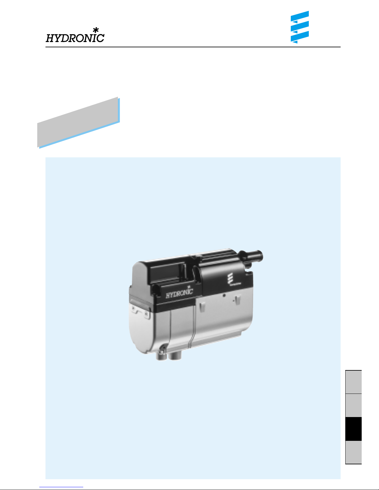
Engine-independent water heater
for petrol
Order No.
HYDRONIC
B 4 W SC – 12 V 20 1824 05 00 00
Universal mounting kit 20 1824 80 00 00
HYDRONIC
B 4 W SC – 12 V
As a complete package 20 1821 05 00 00
Order No.
HYDRONIC
B 5 W SC – 12 V 20 1820 05 00 00
Universal mounting kit 20 1820 80 00 00
HYDRONIC
B 5 W SC – 12 V
As a complete package 20 1823 05 00 00
* Please hand this technical description / mounting instruction
to the customer after installation of the HYDRONIC.
2
D
S
GB
F
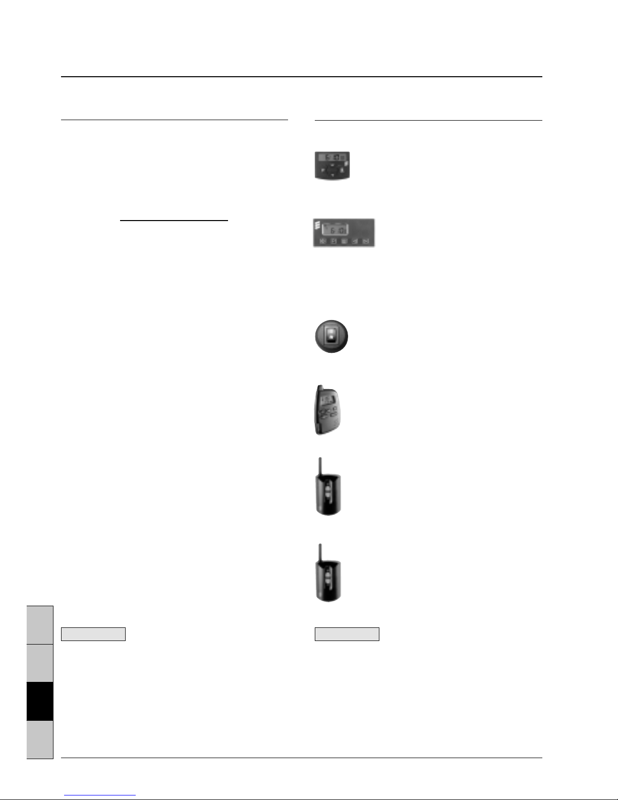
Control elements, optional
Quantity / Designation Order No.
1 Mini-clock – 12 / 24 volt 22 1000 31 31 00
The mini-clock can be combined
with the TP41i radio remote control.
1 Module clock – 12 / 24 volt 22 1000 30 34 00
The module clock can be combined
with the TP4i radio remote control.
1 Mounting parts for the 25 1482 70 01 00
module clock – only required
when installed with a shade
1 Change-over switch 22 1000 31 89 00
‘heating / ventilating’ 12 / 24 volt
Can only be used in combination
with a control element.
1 Remote radio control TP5 22 1000 32 01 00
The bi-directional remote radio control TP5 can be
used on its own for remote control of the heating
in the vehicle.
1 TP4i radio remote control 22 1000 30 99 00
12 / 24 volt
The TP4i radio remote control can only be used
in combination with the module clock.
1 TP41i radio remote control 22 1000 31 39 00
12 / 24 volt
The TP41i radio remote control can be used
on its own or in combination with the mini-clock.
Items supplied
Quantity / Designation Order No.
1
HYDRONIC
B 4 W SC – 12 volt 20 1824 05 00 00
To be additionally ordered:
1 Universal mounting kit 20 1824 80 00 00
or
1
HYDRONIC
B 4 W SC – 12 volt 20 1821 05 00 00
As a complete package*
1
HYDRONIC
B 5 W SC – 12 volt 20 1820 05 00 00
To be additionally ordered:
1 Universal mounting kit 20 1820 80 00 00
or
1
HYDRONIC
B 5 W SC – 12 volt 20 1823 05 00 00
As a complete package*
* The complete package consists of:
1 Heater
1 Universal mounting kit
Optional extras
1 Check valve, Ø 18 mm 254 00 070
1 Check valve, Ø 20 mm 254 00 074
1 Comfort mounting kit (B 5 W SC only) for engines
from 2.5 l cubic capacity 24 0132 00 00 00
The comfort mounting kit includes the following:
1 thermostat, Ø 18 mm
1 T-piece, Ø 18 mm
1 check valve, Ø 18 mm
1 water hose, Ø 18 mm
10 hose clamps
Please refer to the Extra Parts Catalogue for other
additional parts.
ATTENTION!
Before switching on or preprogramming the heating, put
the vehicle’s heating lever (provided the vehicle is
equipped with one) to “HOT” (maximum position) and
the fan to “slowest speed” (low current consumption).
For vehicles with automatic heating, put the heating
lever to “MAX.” and the desired damper position to
“OPEN” before switching off the ignition.
Please note!
Control elements must be selected in accordance
with the intended use of the
HYDRONIC
and on the
basis of the distinction: air or water heater, simple
switching on and off, programme preselection and /
or radio remote control. The control elements are
supplied with operating instructions. These are
intended to be handed over to the customer
together with the mounting and operating
instructions for the
HYDRONIC
.
3
D
S
GB
F
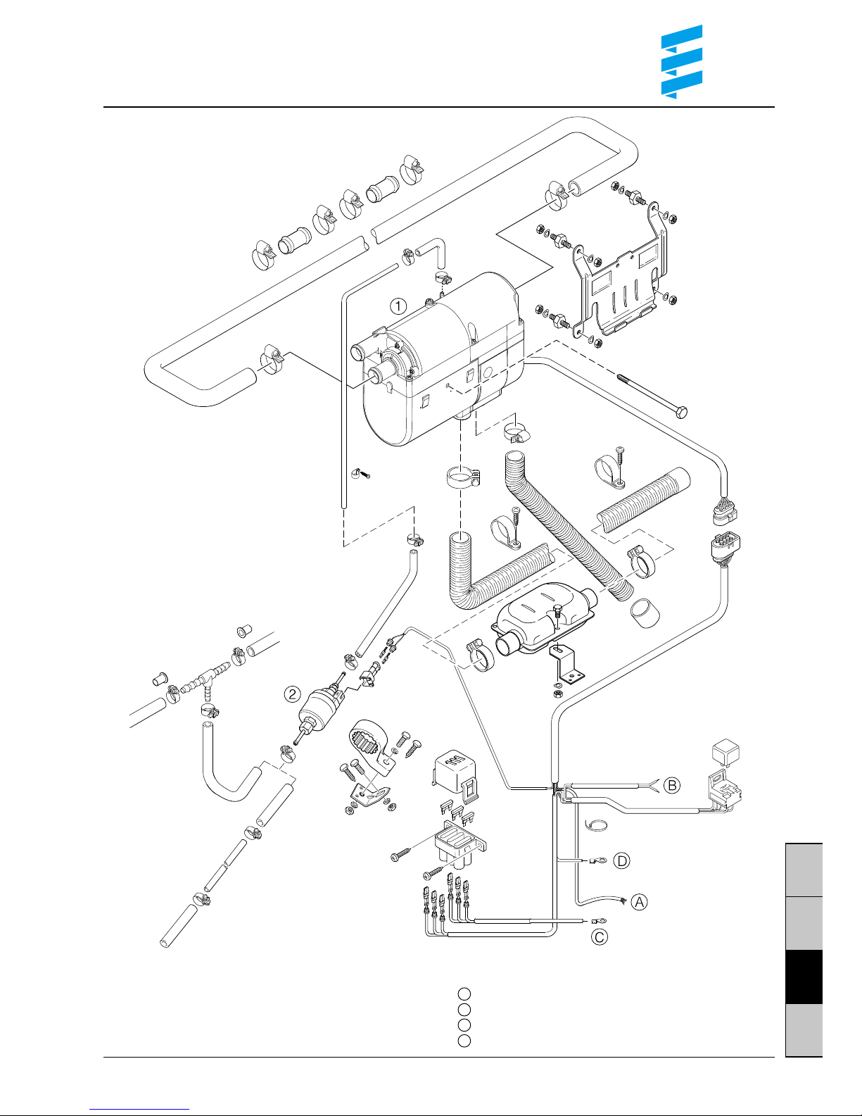
Scope of the delivery
햲
HYDRONIC
B 4 W SC / B 5 W SC
햳 Dosing pump
Parts without drawing number are included
in the universal mounting kit.
Cable harness “control elements”
Cable harness “fan control”
Positive cable
Negative cable
A
B
C
D
4
D
S
GB
F
ATTENTION !
!
§
Safety instructions concerning the
installation and repair of the HYDRONIC
Danger of burns and injury!
Before commencing any work on the
HYDRONIC
,
disconnect the vehicle battery.
Always switch off the
HYDRONIC
prior to any repair work
and allow hot components to cool down.
Statutory regulations concerning
the installation of the HYDRONIC
• For installation in motor vehicles subject to the
Regulations authorizing the Use of Vehicles for Road
Traffic (StVZO), the air heater has been approved by
the German Federal Office for Motor Traffic in keeping
with the ‘General Design Certification’ (AGB) and the
official test symbol is marked on the type plate of the
heater.
HYDRONIC
B 4 W SC S 288
HYDRONIC
B 5 W SC S 288
• The mounting requirements associated with the General Design Certification (AGB) and further statutory
regulations have been printed in the corresponding
sections of these mounting instructions.
• When the air heater is installed in special vehicles, the
regulations governing such vehicles must be taken into
account.
• The year in which the air heater was operated for the
first time must be permanently recorded on the type
plate. To this end, 3 different years have been printed
on the corresponding field of the type plate. The valid
year is to be identified by removing (detaching) those
two years which are not applicable.
• Heaters have to be installed in accordance with the
mounting instructions. The installation must be
checked by an officially approved specialist or
inspector for road traffic, a motor vehicle specialist or
an employee in accordance with paragraph 7.4 a of the
Annex to the StVZO, and must be certified on the
confirmation of acceptance included in the copy of the
general model approval (ABG) according to
a) § 20 StVZO in case of a type approval of vehicles;
b) § 32 StVZO in case of an individual approval;
c) § 19 StVZO in case of an appraisal.
For case c), the vehicle manufacturer, vehicle model
and vehicle identification number must also be
specified.
The validity of the model approval depends on this.
The confirmation of acceptance must be carried in
the vehicle.
• For vehicles not subject to the StVZO, it is necessary
to observe the specific regulations and mounting
instructions applicable to the given vehicle.
• The heater may only be installed or repaired – in case
of the heater being handed in for repair or guarantee
reasons – by a specialist workshop approved by the
manufacturer (service partner) in keeping with these
mounting instructions and possible special installation
recom-mendations.
• The information sticker ‘Switch off heater before
refuelling’ suppplied with the heater must be attached
in a suitable position on the vehicle (close to the fuel
filler neck).
Important instructions for
the installation and repair
of the HYDRONIC
When mounting or repairing the heater, only original
accessories and original spare parts may be used.
Changes to the
HYDRONIC
or to components relevant to
the heating, the use of outside parts not approved by
Eberspächer as well as an installation or operation
differing from the statutory, safety and /or function relevant specifications contained in the mounting instructions and in the operating instructions are not permissible:
this applies in particular to the electric wiring (circuit
diagrams), the fuel supply, the combustion air and exhaust gas duct.
Fuel pipes and exhaust pipes must be safely fastened,
to avoid damage from vibrations (recommendation: at
intervals of approx. 50 cm).
Ensure that the insulation of electrical lines cannot be damaged due to abrasion, kinking, squeezing or by exposure
to heat.
Only the control elements provided and / or approved by
us, either on their own or in a given combination, may be
used to operate the
HYDRONIC
. The use of other control
elements may lead to malfunctions of the heater / heating
operation.
Non-compliance with the statutory, safety and / or
function relevant specifications leads to the lapse of the
General Design Certification (ABG) of the
HYDRONIC
and to the exclusion of guarantee and liability on the part
of the company J. Eberspächer GmbH & Co. KG.
Please note!
• Further ‘Safety instructions concerning the installation
and repair of the
HYDRONIC
’ as well as ‘Important
instructions concerning the installation’ have been
printed directly in the corresponding sections of these
mounting instructions.
• The confirmation of acceptance has been enclosed
with the documents for the
HYDRONIC
.
5
D
S
GB
F
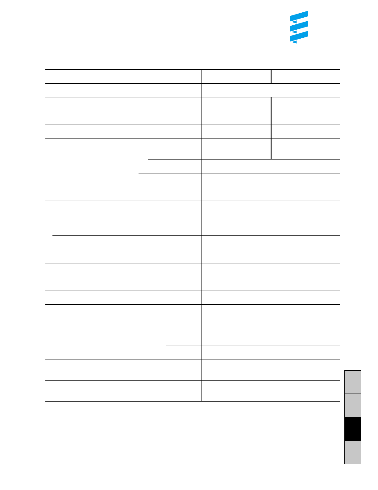
Technical data
Heater B 4 W SC B 5 W SC
Heating medium Water, coolant
Heat flow settings Large Small Large Small
Heat flow (watt) 4300 1500 5000 1500
Fuel consumption (l/h) 0.6 0.2 0.69 0.2
Average electrical power consumption
(watt) During operation 48 22 50 22
When starting 120
During after running 21
Rated voltage 12 V
Operating range
Lower voltage limit 10,2 V
An under-voltage protecting device in the controller
turns off the heater at approx. 10 V
Upper voltage limit 16 V
An over-voltage protecting device in the controller
turns off the heater at approx. 16 V
Permissible working pressure up to 2.5 bar excess pressure
Water throughput of water pump against 0.1 bar 900 l/h ± 100 l/h
Min. water flow rate of heater 250 l/h
Fuel Commercial petrol
For “Fuel quality” and “Fuel at low temperatures” (DIN EN 228)
see Operating Instructions
Permissible ambient temperature Operation –40 °C to +80 °C
Storage –40 °C to +125 °C
Degree of radio interference suppression 2 for LW
3 for VHF / SW / MW
Weight approx. 2.7 kg
including control device, water pump and dosing pump
All technical data ± 10 %
6
D
S
GB
F
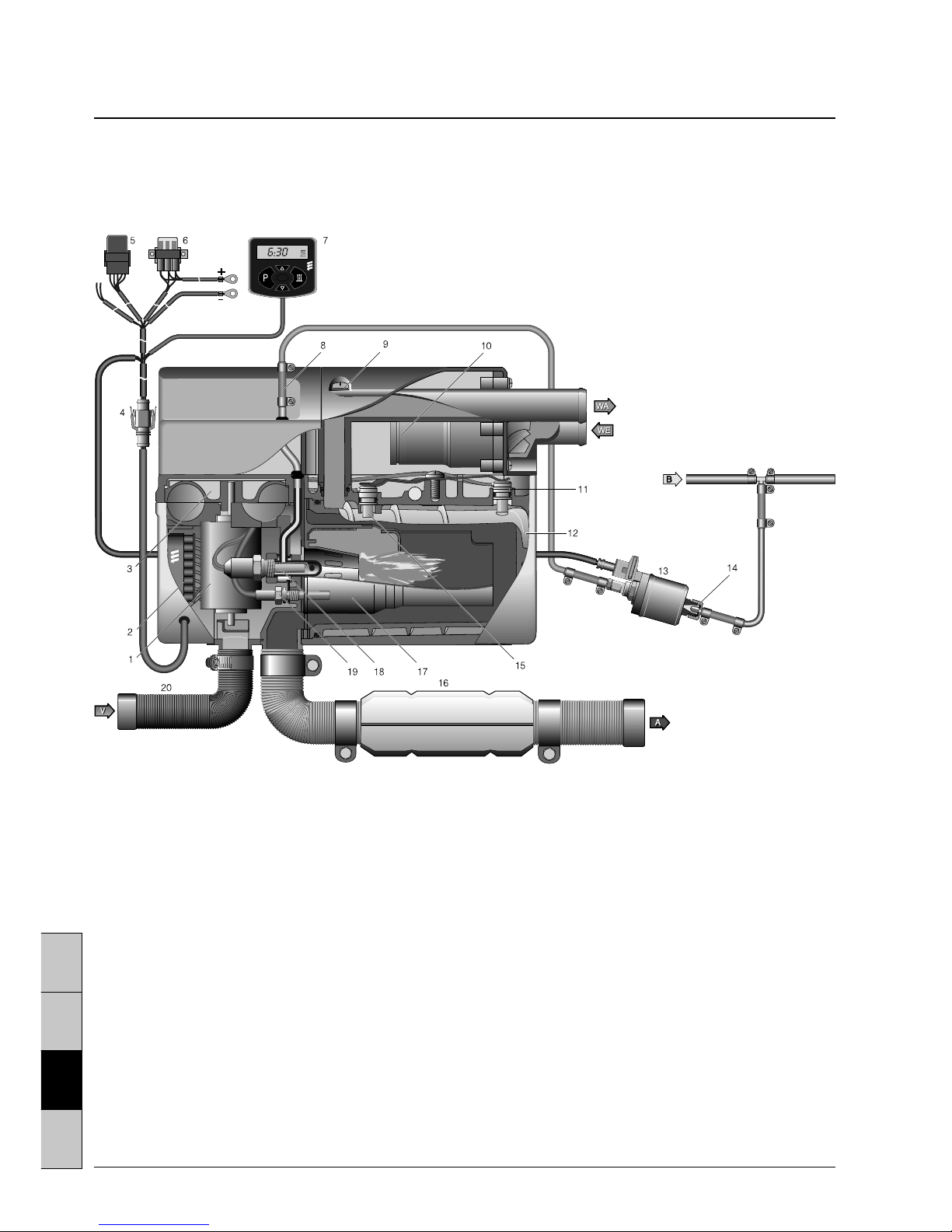
Sectional drawing (shown here is the
HYDRONIC
B 5 W SC)
11 Electric motor
12 Controller
13 Combustion air blower
14 Intersection /
8-channel connector
15 Fan relay
16 Fuse carrier
17 Mini-clock
18 Fuel connection
19 Vent screw
10 Water pump
11 Overheating sensor
12 Heat exchanger
13 Dosing pump
14 Cup strainer, built into dosing pump
15 Temperature probe
16 Exhaust pipe with silencer
17 Combustion chamber
18 Glow plug
19 Flame sensor
20 Combustion air tube
A = Exhaust gas
B = Fuel
V = Combustion air
WA = Water outlet
WE = Water inlet
7
D
S
GB
F
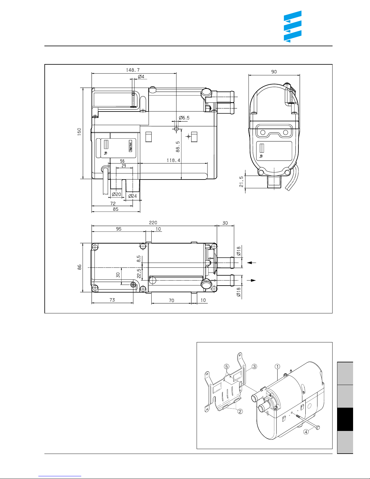
Principal dimensions
Mounting the heater onto the holder
• Insert heater in retaining lugs on holder.
• Screw heater onto holder with fastening screw
(6
+0.5
Nm).
Note:
Depending on the installation space, it is possible
to move the heater inside the holder and to secure it
with screws in one of the two fastening threads.
햲
HYDRONIC
햳 Retaining lugs
햴 Holder
햵 Fastening screw
햶 Fastening threads
8
D
S
GB
F
Mounting instructions
The heater, in conjunction with the vehicle’s heating
system, is used to preheat the engine, to heat the
passenger compartment and to defrost the window
panes.
The heater is connected to the vehicle’s coolingwater circulation, electrical system and fuel system.
If it is wired accordingly, the heater will operate as
additional heater, thereby increasing the heat flow of
the vehicle’s own heating – in particular in the case
of motors with optimised fuel consumption – to a
comfortable level.
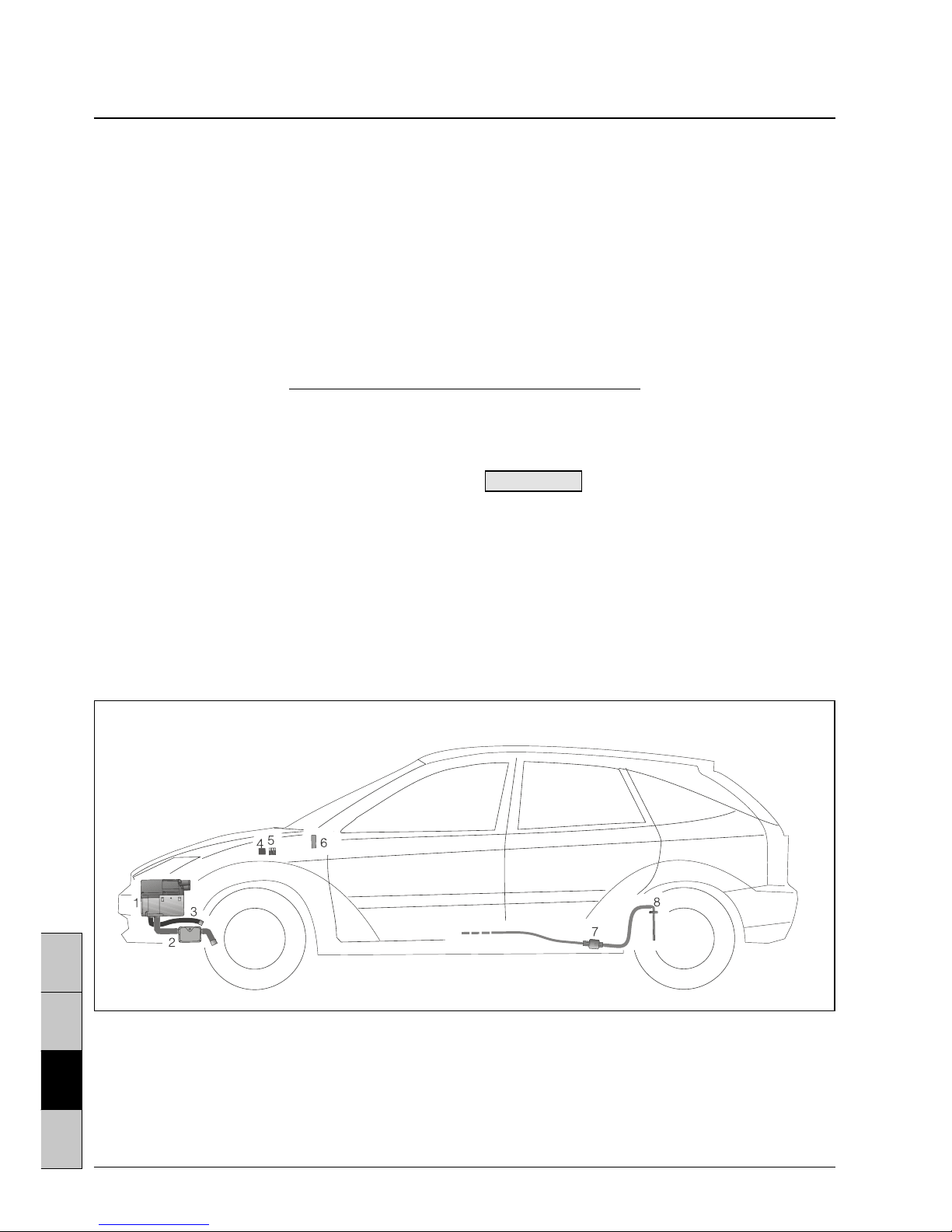
Mounting example
햲
HYDRONIC
햳 Exhaust pipe with silencer
햴 Combustion air tube
햵 Fan relay
(It is not permissible) to install the heater inside
vehicles used for the transport of hazardous substances, inside the passenger compartment, driver’s
cab, working cabin, seating compartment (troop
carrier, mini busses, motorbusses*) and generally in
rooms used by people is not permissible. When
installing the heater in special-purpose vehicles
valid regulations have to be complied with.
* Vehicles with more than 9 seats.
Mounting the heater
Point of installation is the engine compartment.
Mount the heater as deeply as possible so that heat
exchanger and water pump can deaerate automatically. Observe permissible mounting positions as
well as operating and storage temperatures.
Please note!
The proposed points of installation given in these
mounting instructions are examples.
Other points of installation are also permissible
if they comply with the installation requirements
specified in these mounting instructions.
Further information concerning the installation
(e.g. for boats and ships) may be obtained from
the manufacturer on request.
햶 Fuse carrier
햷 Mini-clock
햸 Dosing pump
햹 Rising pipe
 Loading...