

Eberspächer HYDRONIC 16, HYDRONIC 30, HYDRONIC 24, HYDRONIC 35 Troubleshooting And Repair Instructions
Troubleshooting and Repair Instructions
L
D16WN 25 2395 Rev L
S/N 0612051698
16kW
The Troubleshooting and Repair Instructions are applicable to the
following unit versions:
Normal version Order No. Basic unit No.:
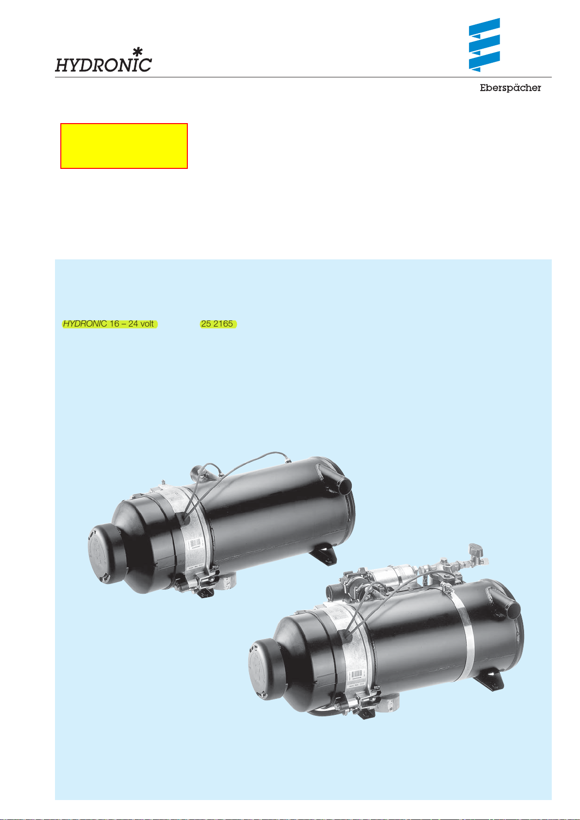
HYDRONIC 16 – 24 volt 25 2165 02 00 00 25 2165 01 00 00
HYDRONIC 24 – 24 volt 25 1817 02 00 00 25 1817 01 00 00
HYDRONIC 30 – 24 volt 25 1818 02 00 00 25 1818 01 00 00
HYDRONIC 35 – 24 volt 25 1819 02 00 00 25 1819 01 00 00
J. Eberspächer GmbH
& Co. KG
Eberspächerstr. 24
D – 73730 Esslingen
Telephone (switchboard)
(0711) 939-00
Facsimile
(0711) 939-0500
www.eberspaecher.com
Compact version Order No. Basic unit No.:
HYDRONIC 24 – 24 volt 25 1817 05 00 00 25 1817 01 00 00
HYDRONIC 30 – 24 volt 25 1818 05 00 00 25 1818 01 00 00
HYDRONIC 35 – 24 volt 25 2041 05 00 00 25 1819 01 00 00
Normal version
25 1818 95 20 12 09.2008 Subject to change without notice Printed in Germany © J. Eberspächer GmbH & Co. KG
Compact version

Introduction
1
Contents
This list of contents provides precise information about the
contents of these Troubleshooting and Repair Instructions.
Chapter Title Contents Page
Introduction
1
Function
2
Product information
3
Troubleshooting
4
Repair instructions
5
• Contents ................................................................................................... 2 – 3
• Foreword ........................................................................................................ 4
• Safety instructions for installation and repair .................................................... 4
• Accident prevention ........................................................................................ 4
• Special text structure, presentation and picture symbols ................................. 4
• Important information before starting work ...................................................... 4
• Cutaway view .................................................................................................. 5
• Structure of the heater .................................................................................... 6
• Special features of the heater .......................................................................... 6
• Operating instructions ..................................................................................... 6
• Description of functions ................................................................................... 6
• Functional diagram .......................................................................................... 7
• Control diagram .............................................................................................. 7
• Control and safety devices .............................................................................. 8
• Emergency stop (EMERGENCY OFF) .............................................................. 8
• Technical data, heater ..................................................................................... 9
• Technical data, water pump .......................................................................... 10
– Pumping and pressure loss characteristic curves ....................................... 10
• What to check fi rst in case of faults ............................................................... 11
• Locking the control box ................................................................................. 11
• Cancelling the control box lock ...................................................................... 11
• Fault diagnosis – fl ashing code ...................................................................... 12
• Overview of the individual test equipment and control units ........................... 13
• External diagnostic system ............................................................................ 13
• Fault diagnosis using the diagnostic unit ................................................. 14, 15
• Fault diagnosis: EDiTH customer service program with ISO adapter .............. 16
• Fault diagnosis: EDiTH customer service program with basic adapter ........... 17
• Fault diagnosis using the module timer .......................................................... 18
• Fault diagnosis using the radio remote control TP5 ....................................... 19
• Fault diagnosis with EasyStart R+ radio remote control
and EasyStart T timer .................................................................................... 20
• Fault code table .................................................................................... 21 – 24
• Repair instructions ........................................................................................ 25
• Always observe the following safety instructions before working on the heater . 25
• AMP release tool ........................................................................................... 25
• Assembly drawing .................................................................................. 26, 27
– Component parts ..................................................................................... 27
• Removing the hood ....................................................................................... 28
• Dismantling the burner .................................................................................. 28
• Dismantling the control box ........................................................................... 28
• Dismantling the burner motor ........................................................................ 29
• Checking the function and speed of the burner motor
using the burner tester .................................................................................. 29
• Dismantling the ignition electrodes ................................................................ 30
• Dismantling the fuel nozzle ............................................................................ 30
• Dismantling the ignition unit ........................................................................... 31
• Testing the ignition unit using the burner tester .............................................. 31
• Dismantling the solenoid valve ....................................................................... 32
• Testing the solenoid valve using the burner tester .......................................... 32
• Dismantling the nozzle block ......................................................................... 33
– Nozzle block made of brass ....................................................................... 33
– Functional check of the heating cartridge ................................................... 33
• Dismantling the fl ame tube ............................................................................ 34
If you are looking for a specifi c term, use the index at the end
of this document.
2

Introduction
1
Contents
Chapter Title Contents Page
5
Repair instructions
Circuit diagrams
6
Service
7
• Dismantling the temperature and overheating sensor .................................... 35
• Temperature and overheating sensor resistance values ................................. 35
– Table of characteristic values - temperature sensor ................................... 35
– Temperature sensor diagram ..................................................................... 35
– Table of characteristic values - overheating sensor ..................................... 36
– Overheating sensor diagram ...................................................................... 36
• Dismantling the gauze fuel fi lter ..................................................................... 37
• Notes on the fuel fl ow rate and the pressure in the fuel system ...................... 36
• Measuring the CO2 content ........................................................................... 37
• Adjusting the combustion air ......................................................................... 37
• Dismantling the water pump (standard design) .............................................. 39
• "Bus 2000" water pump ................................................................................ 39
• Dismantling the FLOWTRONIC 5000 water pump ......................................... 40
• Heater circuit diagram – Part 1 (HYDRONIC 16 / 24 with temperature switch) .. 41
• Heater circuit diagram – Part 1 (HYDRONIC 16 – 35 without temperature
switch) .......................................................................................................... 42
• Heater circuit diagram – Part 2 with water pump (standard design)
and "Bus 2000" water pump ......................................................................... 43
• Heater circuit diagram – Part 3 with FLOWTRONIC water pump .................. 44
• Circuit diagram / parts list for control units ............................................... 45, 46
• Parts list for circuit diagram - EasyStart control units .................................... 47
• EasyStart R control unit circuit diagram ......................................................... 48
• EasyStart R+ control unit circuit diagram ....................................................... 49
• EasyStart T control unit circuit diagram ......................................................... 50
• Certifi cation ................................................................................................... 51
• Disposal ........................................................................................................ 51
• EC Declaration of Conformity ........................................................................ 51
• Representatives abroad .......................................................................... 52, 53
• List of key words ..................................................................................... 54, 55
3
Introduction
1
Foreword
These Troubleshooting and Repair Instructions are applicable
to the heaters listed on the title page, to the exclusion of all liability claims.
Depending on the version or revision status of the heater,
there may be differences between it and these Troubleshooting and Repair Instructions.
The user must check this before carrying out the repair work
and, if necessary, take the differences into account.
Important!
Safety instructions for installation and repair!
Special text structure, presentation and
picture symbols
Special text formats and picture symbols are used in these
instructions to emphasise different situations and subjects.
Please refer to the following examples for their meanings and
appropriate action.
Special text formats and presentations
• A dot (•) indicates a list, which is started by a heading.
– If an indented dash (–) follows a "dot", this list is a sub-
section of the black dot.
Improper installation or repair of Eberspächer heaters can
cause a fi re or result poisonous exhaust entering the inside of
the vehicle. This can cause serious and even fatal risks.
The heater may only be installed according to the specifi cations in the technical documents or repaired using original
spare parts by authorised and trained persons.
Installation and repairs by unauthorised and untrained persons, repairs using non-original spare parts and without the
technical documents required for installation and repair are
dangerous and therefore are not permitted.
A repair may only be carried out in connection with the respective unit-related technical description, installation instructions, operating instructions and maintenance instructions.
This document must be carefully read through before / during installation and repair and followed throughout. Particular
attention is to be paid to the offi cial regulations, the safety instructions and the general information.
Please note!
The relevant rules of sound engineering practice and any information provided by the vehicle manufacturer are to be observed during the installation and repair.
Eberspächer does not accept any liability for defects and
damage, which are due to installation or repair by unauthorised and untrained persons.
Compliance with the offi cial regulations and the safety instructions is prerequisite for liability claims. Failure to comply with
the offi cial regulations and safety instructions leads to exclusion of any liability of the heater manufacturer.
Picture symbols
Danger!
This information points out a potential serious or fatal danger.
Ignoring this information can result in severe injuries.
Important!
This information points out a dangerous situation for a person
and / or the product. Failure to comply with these instructions
can result in injuries to people and / or damage to machinery.
Important information before starting
work
Initial commissioning of the heater or functional test
after a repair
• After installing the heater, the whole fuel supply system must
be carefully vented: please refer to and follow the vehicle
manufacturer's instructions.
• During the heater trial run, all fuel connections must be
checked for leaks and secure, tight fi t.
• If faults occur while the heater is running, use a diagnostic
unit to determine and correct the cause of the fault.
Accident prevention
General accident prevention regulations and the corresponding workshop and operating safety instructions are to be observed.
4

Function
2
Cutaway view
Sketch 1
1 Impeller
2 Electric motor
3 Solenoid valve
4 Flame tube
5 Control box
6 Combustion
chamber
7 Heat exchanger
8 Ignition unit
9 Ignition electrodes
10 Fuel nozzle
11 Coupling
12 Temperature sensor
13 Overheating sensor
14 Relay (vehicle blower control)
15 Fuses
16 Module timer
17 Water pump
18 Exhaust pipe
19 Fuel connection
20 Hood (CO
21 Flame detection photocell
22 Nozzle block with integrated heating
element
adjustment)
2
A Exhaust
B Fuel
V Combustion air
WA Water outlet
WE Water inlet
5

Function
2
Structure of the heater
The heater consists of a heat exchanger and a removable
burner. A combustion chamber consisting of a fl ame tube with
integrated mixer is inserted in the heat exchanger. The fl ame
tube can be pulled out of the heat exchanger if necessary.
The control box and electric motor are fi xed to the burner
fl ange under the burner hood. The fuel pump is integrated in
the burner housing.
The following additional parts are required for operation of the
heater:
• Water pump
• Additional parts for connection to the water circuit
• Additional parts for the fuel supply
• Additional parts for the exhaust system
• Control unit
Order No. see technical description, for further additional parts
see additional parts catalogue.
Special feature of the heater
Description of functions
Switching on the heater
When the heater is switched on, a component test is carried
out (3 seconds) and then the water pump is started up.
Note:
If the water temperature is < 5 °C the nozzle pre-heater is
switched on for 60 seconds; the burner start is delayed by
this length of time.
Burner start
The electric motor starts and drives the combustion air impeller and the fuel pump.
After approx. 10 seconds, the ignition is switched on and then
the fuel solenoid valve opens. Within these 10 seconds a rotational check of the electric motor is carried out. The fuel and
combustion air in the combustion chamber form an ignitable
mixture.
The mixture is ignited by a high-voltage ignition spark. The
fl ame detection photocell detects the fl icker frequency of the
fl ame and switches off the ignition unit. The hot fuel gases
fl ow through the heat exchanger and transfer the heat to the
heating medium.
• If the water fl ow rate is too low, the water outlet temperature
is limited by premature correction.
• The temperature rise of the heating medium is monitored
over time. If it rises too fast (water fl ow rate too low) the
heater automatically switches "OFF" and begins the afterrun, the cycle then begins again.
• Constant comparison of the measured temperature sensor
and overheating sensor values provides additional heater
safety. If the difference between the measured values is
too large (water fl ow rate too low) the heater prematurely
switches "OFF".
Operating instructions
The heater is operated by a control unit. Detailed operating instructions are supplied with the control unit.
Please note!
The operating instructions are issued to you by the garage /
workshop that installs the heater.
Please note!
• The heater operates depending on the heat requirement,
therefore the length of the burner's on-time and off-time
periods differ.
• The water pump continues to run throughout the whole operating period, even during pause mode periods and during
the after-run.
Options
• When the temperature drop is activated the "ON / OFF"
control temperatures are lowered by approx. 8K.
For connection of the ON / OFF switch for temperature
drop, see circuit diagram on pages 43 and 44.
• The water pump can also be operated independently of the
heater, if an appropriate control is installed. For connection of the additional "ON / OFF" switch for separate water
pump control, see circuit diagram on pages 43 and 44.
• For vehicle blower control, the vehicle blower is switched on
and off at the following water temperatures.
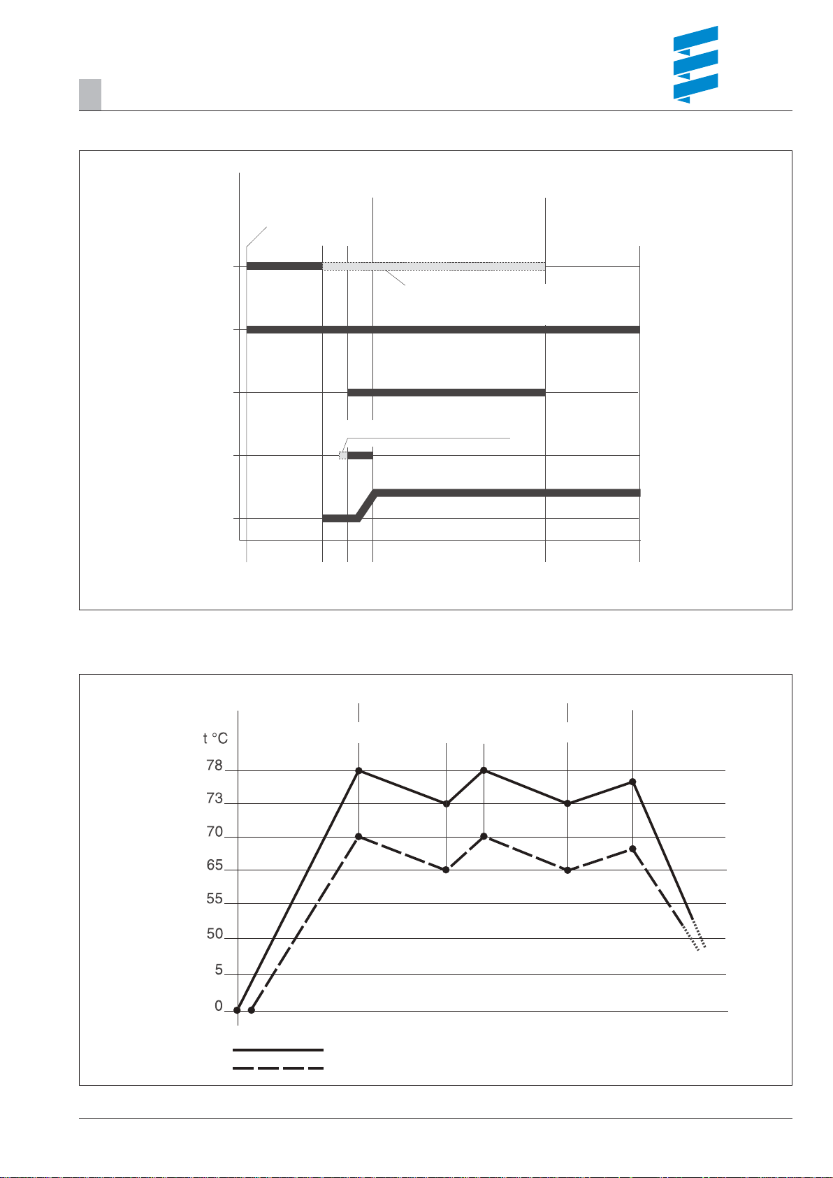
– Water temperature > 55 °C —>Vehicle blower "ON"
– Water temperature < 50 °C —>Vehicle blower "OFF"
Switching off the heater
If the heater is switched off, the fuel solenoid valve closes and
at the same time the approx. 3 minute after-run begins.
After the after-run has fi nished the heater is automatically
switched off.
Please note!
Until it is switched off, including during the after-run, the fuel is
circulated.
6
Function
2
Functional diagram
Heater ON
Components test
Heating mode
Heater OFF
Nozzle block heating
(ON at temperature <5 °C)
Water pump
Solenoid valve
Ignition unit
Electric motor
Sketch 2
Control diagram
60 sec.
3 sec.
From control box 25 1818 53 00 00,
switching "OFF / ON" of the nozzle block
heating is temperature controlled
From control box 25 1818 53 00 00
10 sec.
10 sec.
After running
180 sec.
Vehicle blower ON
Vehicle blower OFF
Sketch 3
Heater ON NORMAL OPERATION Heater OFF
ON ONOFF OFF
After-run – 3 min.
Control – Normal
Control – Temperature drop
7

Function
2
Control and safety devices
The heater is equipped with the following control and safety devices.
• If the heater does not ignite the control box* is locked after
an impermissible number of failed start attempts.
• If the water fl ow rate is too low, the water outlet temperature
is limited by premature correction.
• The temperature rise of the heating medium is monitored
over time. If it rises too fast (water fl ow rate too low) the
heater automatically switches "OFF" and begins the afterrun, the cycle then starts again.
• Constant comparison of the measured values for the temperature sensor and overheating sensor provides additional
heater safety, as a premature lockout (shutdown on faults)
occurs if the difference between the measured values is too
high (the water fl ow rate is too low).
After an impermissible number of lockouts, the control box
is locked.*
• If the lower or upper voltage limit is reached, a lockout
(shutdown on faults) occurs.
• If the fl ame sensor detects a fl ame during the heater's afterrun a lockout occurs (shutdown on faults).
After an impermissible number of lockouts, the control box
is locked.*
* The lock can be cancelled and the faults read out:
• with the module timer / EasyStart T timer
• with the radio remote control TP5 / EasyStart R+.
For other control units by connecting:
• the diagnostic unit
• the customer service program KD2000 / EDiTH.
For details of operation and fault list, see these Trouble-
shooting and Repair Instructions from page 13.
Emergency shutdown – EMERGENCY
OFF
If an emergency shutdown –
EMERGENCY OFF – is required during operation, execute
the following:
• Switch the heater off at the control unit or
• remove the fuse or
• disconnect the heater from the battery.
8
Product information
0.53 Gal/Hr
6 GPM
3
Technical data, heater
Type
Heating medium Mixture of water and refrigerant (max. 50 % refrigerant fraction)
Heat fl ow in watt (at ambient temperature 20 °C) 16 000 24 000 30 000 35 000
Temperature values – at water inlet ON 73 °C / OFF 78 °C
Temperature values – at water outlet ON 85 °C / OFF 118 °C
Fuel Diesel – standard commercial (DIN EN 590) Heating oil EL (DIN 51603)
Fuel consumption (at ambient temperature –10 °C) 2.0 l/h 2.9 l/h 3.65 l/h 4.2 l/h
Rated voltage 24 volt
Operating range
• Lower voltage limit:
An undervoltage protector installed in the control box
switches off the heater if the voltage limit is reached.
• Upper voltage limit:
An overvoltage protector (surge suppressor) installed
in the control box switches off the heater if the voltage
limit is reached.
Electrical power consumption
(in combustion mode / without circulating pump)
D 16 W N D 24 W N D 30 W N D 35 W N
60 watt 80 watt 105 watt 120 watt
HYDRONIC L
19 volt
30 volt
Water content of the heat exchanger approx 2 l
Water content of the water circuit min. 10 l
Minimum heating medium fl ow rate (±200 l/h) 1400 l/h 2000 l/h 2600 l/h 3000 l/h
Permissible ambient temperature in operation:
during transport / storage:
for the combustion air:
Pumped medium:
Operating pressure (water circuit) < 2.5 bar
values (% vol) 9 – 11 9 – 11 9 – 11 9.5 – 11.5
CO
2
CO in the exhaust < 0.04
Smoke spot no. (Bacherach) < 4
Weight approx 18 kg
Interference suppression class VHF 4 / SW 3 / MW 5 / LW 3 according to DIN 57879 / Part 1
Protection IP 64
–40 °C to +85 °C
–40 °C to +100 °C
< 60 °C
–40 °C to +90 °C,
short-term up to +120 °C
VDE 0879
Important!
Safety instructions for technical data!
Failure to comply with the technical data can result in malfunctions.
Please note!
If no limit values are given, the technical data listed is with the
usual heater tolerances of ± 10 % at nominal voltage, 20 °C
ambient temperature and Esslingen reference altitude.
9

Product information
3
Technical data, water pump
Heating medium Mixture of water and refrigerant (max. 50 % refrigerant fraction)
Delivery rate 5200 l/h ±10 % at 0.2 bar discharge pressure
Water circuit operating pressure max. 2 bar
Weight (without bracket, clamp and refrigerant) 2.14 kg
Rated voltage 24 volt
Operating range 20 – 28 volt
Power consumption at 5200 l/h and 0.2 bar discharge pressure
Interference suppression class 3 according to DIN 57879 / Part 1 VDE 0879
Protection IP 54A according to DIN 40 050 Sheet 1
Electrical fusing for third party control 15 A
Temperature conditions Heating medium –40 °C to + 90 °C [short-term (15 min.) +115 °C]
Ambient, operation
Dry running No
Blocking Within a period of max. 6 seconds the motor is undamaged.
Shaft - impeller connection Mechanical seal
FLOWTRONIC 5000
104 watt ±10 %
–40 °C to 90 °C [short-term (15 min.) +115 °C]
Pumping and pressure loss characteristic curves
Sketch 4
Please note!
• If no limit values are given, the technical data listed is with
the usual heater tolerances of ± 10 % at nominal voltage,
20 °C ambient temperature and Esslingen reference altitude.
• The FLOWTRONIC 5000 water pump is installed in com-
pact design heaters.
• If water pumps are ordered separately, please refer to the
documentation supplied with them for the relevant technical
data, installation positions, etc.
Flow resistance (when pump at rest)Volumetric fl ow rate (with water at 20 °C)
Important!
Safety instructions for technical data!
Failure to comply with the technical data can result in malfunctions.
10

Troubleshooting
4
What to check fi rst in case of faults
• Faulty wiring (short circuits, interruption).
• Visual inspection for
– corroded contacts
– defective fuses
– damaged electrical leads, connections and terminals
– damaged exhaust and combustion air circuit.
• Battery voltage when heater started <19 Volt (measure voltage at control box).
• Check fuel supply.
• On changeover to winter service: Is summer diesel still in
the line?
• Delayed start –> nozzle block heating switched on for
60 seconds.
• The Bus 2000 water pump and the HYDRONIC are automatically switched off shortly after the start if there is no
refrigerant or if the pump impeller is blocked.
Locking the control box
The control box is locked if the following faults occur:
• Overheating
If the heater overheats 3x in succession – fault code 012, is
displayed as AF 015 –> the control box is locked.
• Flame in after-run
If the fault "fl ame in after-run" is signalled 3x in succession
– fault code 058, is displayed as AF 016 –> the control box
is locked.
• Too many attempted starts
If the heater carries out ten failed start attempts in succes-
sion – fault code 052, is displayed as AF 050 –> the control
box is locked.
Cancelling the control box lock
Cancellation of the control box lock is described on pages 15
to 20.
Cancelling control box lock without diagnostic equip-
ment
If the heater is switched on, apply plus at 18-pin cable harness connector, pin 13, cable 1
control) for approx. 3 sec. –> the control box is unlocked.
Additional option from control box
25 1818 53 00 00 with Bus 2000 water pump fault
Apply plus at 18-pin cable harness connector, pin 9, cable 1
bl/sw for approx. 3 sec. –> the control box is unlocked.
2
ge/rt (water pump third party
2
11

Troubleshooting
Too many attempted
starts
4
Fault diagnosis – fl ashing code
(LED with series resistor)
The electronic control box can store up to 5 faults.
The defective component and type of fault are output by the
control box as a fl ashing code and are displayed by an LED
with series resistor (approx. 1 kΩ / 1W).
The LED with series resistor is connected to the 8-pin connector of the heater cable harness (chamber 2, cable 12 bl/ws
and chamber 5, cable 1
2
ge).
The fl ashing codes of the defective components and the corresponding fault codes are described on page 12.
Possible causes and remedial action are explained in the fault
code tables (pages 21 – 24).
Flashing code
400 ms pause at the start
of the fl ashing code
Operation without faults
Flame detection photocell,
Fault code 16, 51, 58
Safety time exceeded,
Fault code 50, 52
LED and series resistor
Sketch 5
8 sec. 16 sec.
resistor
LED
connector B2
chamber 5
chamber 2
8
64
2
1753
connector B1
1
4
5
2
3
6
Flame cutout
Fault code 54
Overheating
Fault code 12, 15
Burner engine
Fault code 32, 33
Undervoltage cut-off
Fault code 11
Overvoltage cut-off
Fault code 10
Temperature sensor
Fault code 14, 60, 61, 71, 72
Connection error
Fault code 20, 21, 25, 37 – 39, 44 – 49, 80 – 83
Control box
Fault code 90 – 97
Short pulse – fl ash duration: 0.4 sec.
Long pulse – fl ash duration: 2.0 sec.
Pause between the pulses: 0.4 sec.
Period of a fl ashing sequence: 8.0 sec.
Sketch 6
12

Troubleshooting
4
Overview of the individual test equipment
and control units
The electronic control box can store up to 5 errors, which can
be read out and displayed. The following test equipment can
be used to query the fault memory in the control box and if
necessary to delete the control box locking:
Test equipment Order No.:
• Diagnostic unit 22 1529 89 00 00
additionally required:
Adaptor cable 22 1000 31 66 00
• EDiTH customer service program
– Basic adapter with software 22 1532 89 00 00
additionally required:
HYDRONIC L extension 22 1539 89 00 00
– ISO adapter 22 1524 89 00 00
additionally required:
Adaptor cable 22 1000 31 66 00
• Burner tester 22 1527 89 00 00
If a diagnostics cable is connected, the following control units
can also be used to query the fault memory in the control box
and if necessary to delete the control box locking:
Control units Order No.:
• Module timer 22 1000 30 34 00
• TP5 radio remote control 22 1000 32 01 00
• EasyStart T 22 1000 32 88 00
• EasyStart R+ 22 1000 32 80 00
Please note!
If the fault memory cannot be read out, check the diagnostics
cable for correct laying and possible damage.
External diagnostic system
With an external, vehicle-specifi c diagnostic system
–> contact the vehicle manufacturer.
13
Troubleshooting
4
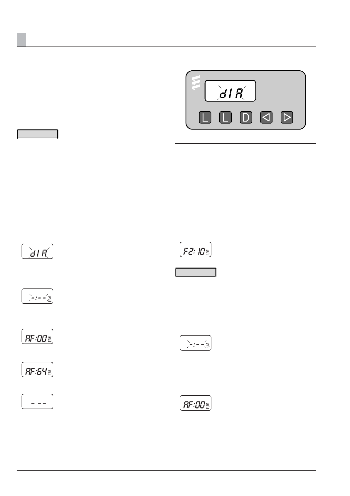
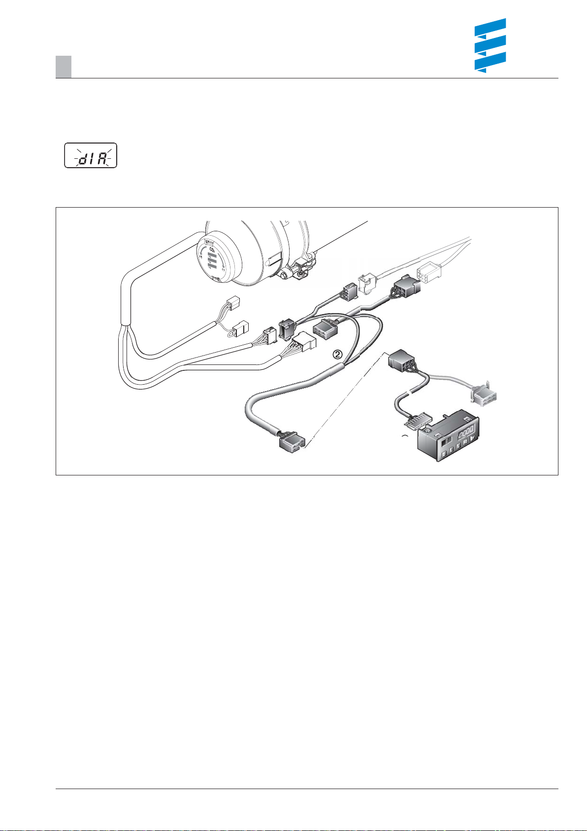
Diagnostic unit
(Order No.: 22 1529 89 00 00)
To connect the diagnostic unit, an additional
adapter cable is required (Order No.: 22 1000 31 66 00).
The current fault is displayed as "AF“ and a 2-digit number
and is always written in the memory location F1.
Preceding faults are moved to the memory locations F2 – F5,
if necessary the contents of memory location F5 is overwritten.
Please note!
• Not only the defective component, but also a defective current circuit results in a fault being displayed.
• Fault code, fault description, cause / remedial action are
described on Pages 21 – 24.
Connect diagnostic unit
• Disconnect the 8-pin connector of the heater's cable harness and connect the adapter cable.
• Connect the diagnostic unit to the adapter cable.
Display is as follows:
Query fault memory
• Use the D key to switch on the heater.
Display is as follows:
• After 8 sec the following is displayed:
Display is as follows:
Sketch 7
– Delete fault memory
l
– Delete fault memory
l
– Switch heater on / off, request diagnosis
d
– Return, F5 – F1
e
– Flow, F1 – F5, current fault (AF)
f
Display of the fault memory F1 – F5 or F5 – F1
• Press the
display the fault memory.
Display is as follows:
e.g. fault memory 2 / fault code 10
Please note!
Only the fault memory locations with an error assigned to
them are displayed.
Delete fault memory
• Press both L buttons simultaneously until the following appears in the display:
Display is as follows:
or f button again, or press several times, to
e
Heater has no malfunction
or
e.g. current error / fault code 64
or
Fault diagnosis not possible
Possible causes:
– Adapter cable is not properly connected.
– Control box is defective or is not capable of diagnosing
(not a universal control box).
14
• If the fault memory has been deleted the most recent current fault is displayed. The current fault is not reset to 00
until the heater is restarted – provided there is no new, more
recent fault.
Display is as follows:
Heater has no faults
Troubleshooting
4
Cancel the control box lock
• Delete the fault memory as described and switch off the
heater using the d key.
• The control box lock is cancelled and the diagnosis closed.
Display is as follows:
Sketch 8
Diagnostic unit with connection cable
Adaptor cable
15
Troubleshooting
4
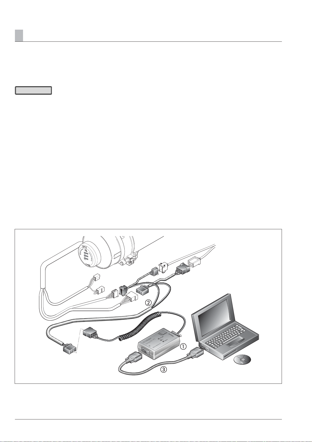
EDiTH customer service program
with ISO adapter
(Order No.: 22 1524 89 00 00)
An additional adapter cable is required to connect the ISO
adapter (Order No.: 22 1000 31 66 00).
Please note!
• It is very important to always install in the given order.
• Not only the defective component, but also a defective current circuit results in a fault being displayed.
• Fault code, fault description, cause / remedial action are
described on Pages 21 – 24.
• The EDiTH customer service program software is not included in the scope of supply, it must be downloaded from
the service portal.
• Faults 1 – 5 only are displayed in heaters up to serial No.
12 000.
In addition to faults 1 –5, measured values are also dis-
played in heaters from serial No. 12 001.
Connect ISO adapter
• Disconnect the heater's cable harness.
• Connect the adapter cable to the cable harness – as shown
in the sketch.
• Connect the adapter cable to the ISO adapter.
• Connect the SUB-D connection cable with the PC and the
ISO adapter.
Installing software on the PC
• Double-click "setup.exe" fi le to start and
follow the SETUP program instructions.
Query / delete fault memory F1 – F5
or cancel the control box lock
• Start the software at the PC:
– on the desktop —> double-click the "EDiTH" icon
– Select heater type
– Press the "GO" button.
• Delete fault memory or cancel the control box lock:
– Press the "Delete fault memory" button
—> the stored faults F1 – F5 are deleted and the control
box is unlocked.
Quit diagnosis
• Press the "STOP" button —> fault memory query is ended.
Sketch 9
ISO adapter
Adaptor cable
SUB-D connection cable
16
Troubleshooting
4
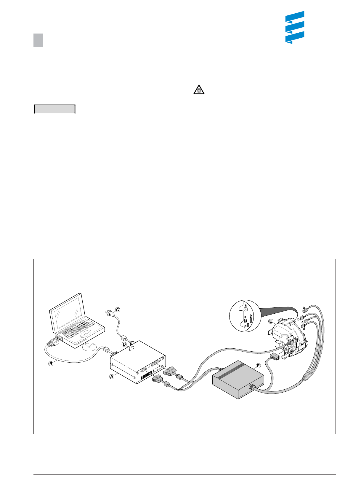
EDiTH customer service program
with basic adapter
EDiTH basic adapter
(Order No.: 22 1532 89 00 00)
An additional extension is required to check the control box
(Order No.: 22 1539 89 00 00).
Please note!
• It is important to always follow the precise connection order
as given below!
• The fl ame failure safeguard integrated in the control box can
only be tested properly if the corresponding mating connector (a) is connected.
• Only push or pull on the connectors, not on the cables!
• Only use the network cable and RS232 cable with snap
ferrites included in the scope of supply. Use original accessories with snap ferrites only to connect the test equipment.
• Not only the defective component, but also a defective current circuit results in a fault being displayed.
• Fault code, fault description, cause / remedial action are
described on Pages 21 – 24.
Important!
Magnetic fi eld!
During the test operation a magnetic fi eld develops at the
adapter. Therefore, do not place any objects such as data
media, credit cards, etc. on the adapter or in its immediate vicinity.
Connect basic adapter
• Start computer and wait until the system has successfully
booted.
• Start PC software.
• Insert the unit connector of the mains cable in the basic
adapter and connect the mains connection to the mains.
• Connect the SUB-D connection cable with the PC and
basic adapter.
Connect extension and test control box
• Connect the extension to the basic adapter.
• Connect extension and basic adapter to control box.
• Switch on basic adapter at mains switch.
• Select the control box version and operating voltage
(12 V / 24 V) in the PC software.
• Start the control box test with the PC software.
A more detailed description of how to operate the basic
adapter is given in the EDiTH online help.
(A) Basic adapter
(B) SUB-D connection cable
(C) Mains connection
(D) Mains switch
(E) Control box
(F) Extension
Sketch 10
17
 Loading...