

Page 1
VEHICLE HEATERS | TECHNICAL DOCUMENTATION
OPERATING INSTRUCTIONS
EASYSTART REMOTE
CONTROL UNIT FOR
EBERSPÄCHER PARKING HEATERS
EN
OPERATING INSTRUCTIONS
INSTALLATION INSTRUCTIONS
A WORLD OF COMFORT
Page 2
2 | VEHICLE HEATERS – TECHNICAL DOCUMENTATION
CONTENTS
CHAPTER CHAPTER TITLE
CHAPTER CONTENTS PAGE
1 INTRODUCTION
Please read first 4
Safety information 4
Statutory regulations 4
Range of uses 4
General information 5
2 OVERVIEW
EasyStart Remote mobile unit 6
Button functions 6
button ON 6
button OFF 6
LED indications 6
3 OPERATION AND SETTING/ADJUSTMENT
Notes on operation and setting 8
Switch on the heater 9
Switch off heater 9
Query the operating state of the heater 10
Permanently change the operating time 10
Switch to HEATING or VENTILATION 12
Function pushbuttons 13
Page 3

CONTENTS
4 MAINTENANCE
Charged status of the mobile unit's battery 14
Replacing the battery 14
5 WHAT TO DO IF …?
In the event of a fault the following flashing signals are possible: 15
The following faults are possible 16
6 SERVICE
Hotline 17
VEHICLE HEATERS – TECHNICAL DOCUMENTATION | 3
Page 4
4 | VEHICLE HEATERS – TECHNICAL DOCUMENTATION
1 INTRODUCTION
PLEASE READ FIRST
Before you start to set and use the timer,
always read through these operating instructions carefully.
These operating instructions contain important information that you require for to set and
use the timer.
Please keep these operating instructions in a
safe place for subsequent reference.
SAFETY INFORMATION
DANGER!
Always note and follow all information and
notes, especially the safety instructions in
this document and in the heater's technical description!
Only the battery cover of the mobile unit
may be opened.
The battery and battery cover must be kept
out of reach of children – swallowed small
parts.
Before washing clothing, remove the mobile
unit from pocket.
Protect the mobile unit from adverse
effects (impacts, extreme temperatures,
moisture, rain, liquids).
The mobile unit and heater must be
switched off when refuelling.
Dispose of the battery and mobile unit
according to the statutory regulations.
Only use the recommended battery and
original spare parts (from page 14).
STATUTORY REGULATIONS
RETURN / DISPOSAL OF ELECTRICAL AND
ELECTRONIC EQUIPMENT IN ACCORDANCE
WITH § 4 PARAGRAPH 1 ALT FZ-VO (END OF
LIFE VEHICLE REGULATIONS)
As a part of the vehicle, when the vehicle is
handed over to a recognised waste collection
body, a recognised returns body or a recognised dismantling firm, the radio remote control must be placed in the vehicle for return in
accordance with Art 4 Paragraph 1 Alt Fz-VO.
RANGE OF USES
The EasyStart Remote radio remote control
is used to select the operating mode, to set
the operating time and to switch On / Off the
heater installed in the vehicle.
PLEASE NOTE!
Improper use and use outside the specified
area of use cancels all liability and warranty.
Page 5

1 INTRODUCTION
GENERAL INFORMATION
The mobile unit of the EasyStart Remote
radio remote control has a simple control
structure.
All functions can be set and, if necessary,
changed with only 2 buttons.
The pulses of the mobile unit have a range
of up to 1000 metres outdoors (direct visual contact). External interference, local
conditions and high building density in the
surrounding area shorten the range.
The mobile unit should always be pointed
towards the vehicle when activated or for
data transmission.
Depending on the use and ambient effects,
different flashing sequences can be displayed, which are described in the chapter
“What to do if …?” from page 15.
Use of the mobile unit is described in detail
from page 8.
VEHICLE HEATERS – TECHNICAL DOCUMENTATION | 5
Page 6
6 | VEHICLE HEATERS – TECHNICAL DOCUMENTATION
2 OVERVIEW
EASYSTART REMOTE MOBILE UNIT
The mobile unit of the EasyStart Remote radio
remote control can be used to switch the
heater on and off. Further, it can be used to
make the necessary settings for operation of
the heater.
PLEASE NOTE!
The type of LED displays possible differs
depending on the installed heater and feature
options.
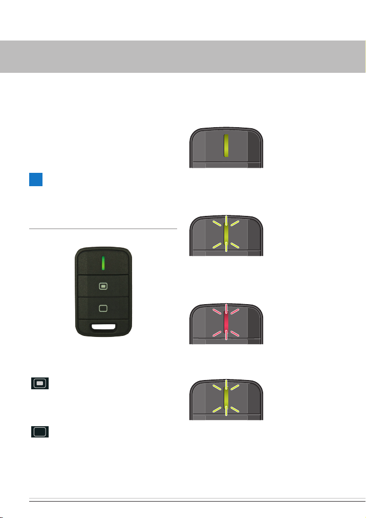
BUTTON FUNCTIONS
button ON
Heater ON.
Confirm settings.
LED INDICATIONS
DATA TRANSMISSION
LED indicator
lights up green.
HEATER ON
HEATING or VENTILATION
LED indicator
flashes green (12x).
HEATER OFF
HEATING or VENTILATION
LED indicator
flashes red (12x).
HEATER IS IN OPERATION
LED indicator
flashes green (5x).
button OFF
Heater OFF.
Make settings.
Page 7

2 OVERVIEW
PLEASE NOTE!
Possible LED indications such as alternating red-green flashing, red flashing or continuously lit red are described in the chapter
“What to do if …?” from page 15.
Entries can also be made during the flashing
stations, but not during the data transmission.
VEHICLE HEATERS – TECHNICAL DOCUMENTATION | 7
Page 8

8 | VEHICLE HEATERS – TECHNICAL DOCUMENTATION
3 OPERATION AND SETTING/ADJUSTMENT
NOTES ON OPERATION AND SETTING
ACTUATE THE MOBILE UNIT
Each press of the button results in an action,
which is indicated by flashing.
The flashing indicator goes out automatically.
Before each operation or setting, a connection
must be established between the mobile unit
and the stationary unit.
To do this, press the
LED indicator lights up green permanently,
then release the button and continue with the
operation or setting (see from page 9).
button until the
PERMANENTLY CHANGE THE OPERATING TIME
10, 20, 30, 40, 50 or 60 minutes can be set
as the operating time (factory setting is 30
minutes).
See from page 10 for adjustment.
DATA TRANSMISSION
During data transmission the LED display is
permanently lit green.
During the data transmission it is not pos-
sible to make settings or adjustments.
PLEASE NOTE!
If data transmission was not possible the LED
indicator flashes 12x red / green.
Page 9

VEHICLE HEATERS – TECHNICAL DOCUMENTATION | 9
3 OPERATION AND SETTING/ADJUSTMENT
SWITCH ON THE HEATER
HEATING OR VENTILATION
Press the button, the connection is set up
with the stationary unit is.
Data transmission
LED: lights up green
LED: flashes 12x
green
The heater is switched on.
Operating time 30 minutes (factory setting)
PLEASE NOTE!
The following action is possible during operation:
Query the operating state of the heater
(see page 10).
SWITCH OFF HEATER
HEATING OR VENTILATION
Press the
with the stationary unit is.
button, the connection is set up
Data transmission
LED: lights up green
LED: flashes 12x red
The heater is switched off.
PLEASE NOTE!
The following actions are possible after
switching off:
Switch heater back on again.
Change operating time (see from page 10).
Switch to HEATING or VENTILATION.
(from page 12).
Page 10

10 | VEHICLE HEATERS – TECHNICAL DOCUMENTATION
3 OPERATION AND SETTING/ADJUSTMENT
QUERY THE OPERATING STATE OF THE
HEATER
Press the
with the stationary unit is.
The following indications are possible:
if the heater is ON
if the heater is OFF heater is switched on
If heating mode or ventilation mode is not
required, press the
switched off.
Possible LED indications such as alternating red-green flashing, red flashing or continuously lit red are described in the chapter
“What to do if …?” from page 15.
button, the connection is set up
Data transmission
LED: lights up green
LED: flashes 5x
green
LED: flashes 12x
green
button; the heater is
PLEASE NOTE!
PERMANENTLY CHANGE THE OPERATING TIME
Keep the button pressed until “CURRENT
OPERATING TIME WILL BE DISPLAYED AS
FLASHING” appears.
PLEASE NOTE!
A switched on heater is switched off with this
setting.
Data transmission
LED: lights up green
LED: flashes red for
8 seconds
Data transmission
LED: lights up green
Current operating
time is indicated
by flashing, e.g. 3x
red for 30 minutes
operating time.
Release the
nals follow for the selection of the operating
time (see page 11).
button; further flashing sig-
Page 11

VEHICLE HEATERS – TECHNICAL DOCUMENTATION | 11
3 OPERATION AND SETTING/ADJUSTMENT
SELECTION OF THE OPERATING TIME
10 minutes operating time
LED: flashes 1x red
20 minutes operating time
LED: flashes 2x red
30 minutes operating time
LED: flashes 3x red
40 minutes operating time
LED: flashes 4x red
50 minutes operating time
LED: flashes 5x red
60 minutes operating time
LED: flashes 6x red
Confirm the selected operating time in the
pauses between the respective flashing
sequences by pressing the
button.
Data transmission
LED: lights up green
LED: flashes e.g.
4x red
The selected operating time is saved and
is indicated by flashing once again (e.g.
LED flashes 4x red for an operating time of
40 minutes).
PLEASE NOTE!
The flashing signals for selection of the
operating time are indicated from the current
operating time up to the 60th minute and then
twice completely from the 10th to the 60th
minute.
Mobile unit is then OFF (Standby).
The setting can be exited with a timeout.
Do not press the
setting, as otherwise the operating mode
changes.
button during the
Page 12

12 | VEHICLE HEATERS – TECHNICAL DOCUMENTATION
3 OPERATION AND SETTING/ADJUSTMENT
SWITCH TO HEATING OR VENTILATION
PLEASE NOTE!
This function is only possible if the heater
supports the VENTILATION function.
A switched on heater is switched off with this
setting.
Keep the
OPERATING TIME IS DISPLAYED” appears.
button pressed until “CURRENT
Data transmission
LED: lights up green
LED: flashes red for
8 seconds
Data transmission
LED: lights up green
The current operating time is indicated
by flashing.
PLEASE NOTE!
Make the following setting within 30 seconds
of letting go of the
Press the
mode is changed.
Switch from HEATING to VENTILATION
Switch from VENTILATION to HEATING
PLEASE NOTE!
The operating mode is permanent until it is
changed over again.
The setting can be exited with a timeout.
button.
button again; the operating
LED: flickers green
for approx. 10
seconds
LED: flickers red for
approx. 10 seconds
Release the
time is flashing.
button while the operating
Page 13

VEHICLE HEATERS – TECHNICAL DOCUMENTATION | 13
3 OPERATION AND SETTING/ADJUSTMENT
FUNCTION PUSHBUTTONS
The following activities can be executed with
the buttons installed in the vehicle:
Start heating mode, the last entry made for
the operating time applies (button LED On).
Switch off heater mode (button LED Off)
Teach the mobile unit, see installation
instructions.
Page 14

14 | VEHICLE HEATERS – TECHNICAL DOCUMENTATION
4 MAINTENANCE
CHARGED STATUS OF THE MOBILE UNIT'S
BATTERY
LED: lights up red
for 4 seconds
If the LEDindicator of the mobile unit indicates that the battery is too weak with a red
indicator, purchase a CR 2032 type round cell
battery made by Varta, Sony or Renata, as
recommended by JE-Eberspächer.
REPLACING THE BATTERY
Insert new battery.
The battery has been correctly inserted if
the plus pole symbol and the type designation of the battery can be read.
Put on the battery compartment cover and
latch into place.
Activate the mobile unit (see page 8).
Open the battery compartment
Remove dead battery.
Page 15

VEHICLE HEATERS – TECHNICAL DOCUMENTATION | 15
5 WHAT TO DO IF …?
IN THE EVENT OF A FAULT THE FOLLOWING FLASHING SIGNALS ARE POSSIBLE:
LED INDICATOR POSSIBLE CAUSES REMEDY / CUSTOMER
Fault heater. Visit your vehicle workshop.
On pressing the
button, slow red-
flashing 5x
After pressing the
or button, fast redgreen flashing 12x
(Communication is not
possible between the
mobile unit and stationary unit.)
or
The EasyStart Remote has been
disconnected from the power
supply and then reconnected.
Distance between mobile unit
and vehicle too large.
Dense buildings between the
mobile unit and vehicle.
Several radio remote controls
are being used simultaneously.
Mobile unit has not been taught. Teach mobile unit as described in
Teach mobile unit as described in
the installation instruction.
Wait until the automatic detection
has finished.
Reduce distance.
Change the position relative to
the vehicle e.g. hold mobile unit
higher or move it to the side.
Reduce distance from vehicle.
Reactivate the mobile unit after
a pause.
the installation instruction.
PLEASE NOTE!
The unit cannot be used during the “redgreenflashing” signal. A switched on heater can only
be switched off using the button in the vehicle.
LED flashes quickly
(flickers) green (6 seconds)
LED lights up red following activation (4 seconds)
Stationary unit is in learn mode. Teach mobile unit as described in
the installation instruction.
Wait until the automatic detection
has finished.
The mobile unit's battery is too
weak. Data transmission is not
possible.
Replace battery (see page 14).
Page 16

16 | VEHICLE HEATERS – TECHNICAL DOCUMENTATION
5 WHAT TO DO IF …?
THE FOLLOWING FAULTS ARE POSSIBLE
FAULT POSSIBLE CAUSES REMEDY /CUSTOMER
The mobile unit cannot
be activated
Battery dead.
No battery inserted.
Replace battery (see page
14).
Insert battery (see page 14).
Battery inserted wrong way
around.
LED at the button flashes Stationary unit is in learn mode. The display switches itself off
PLEASE NOTE!
If you are unable to remedy the error or fault,
please contact an authorised JE workshop or
dial the following service phone number.
Insert battery correctly (see
page 14).
after 30 seconds or teach the
mobile unit as described in the
installation instruction.
Page 17

6 SERVICE
HOTLINE
If you have any technical questions, a problem with the EasyStart Remote radio remote
control or the heater, dial the following service
phone number from within Germany.
Hotline: 0800 1234300
Fax hotline: 01805 262624
Outside of Germany, please contact
the respective Eberspächer national
representative.
VEHICLE HEATERS – TECHNICAL DOCUMENTATION | 17
Page 18

18 | VEHICLE HEATERS – TECHNICAL DOCUMENTATION
Page 19

VEHICLE HEATERS – TECHNICAL DOCUMENTATION | 19
Page 20

Headquarters:
Eberspächer Climate Control Systems
GmbH & Co. KG
Eberspächerstraße 24
73730 Esslingen
Hotline: 0800 1234300
Fax hotline: 01805 262624
info@eberspaecher.com
www.eberspaecher.com
22 1000 34 23 02 06.2013 Subject to change without notice © Eberspächer Climate Control Systems GmbH & Co. KG Printed in Germany
 Loading...