

Eberspächer D8LC Installation, Operation And Maintenance Instructions
Heater Order no.
D 8 L C – 12 volt 25 1890 00 00 00
D 8 L C – 24 volt 25 1891 00 00 00
Air heater 8 L
Technical description, installation,
operation and maintenance instructions.
Engine-independent air heater
for diesel fuel
25 1891 90 96 66
04.2009
2
8
7
6
5
4
3
2
1
Introduction1
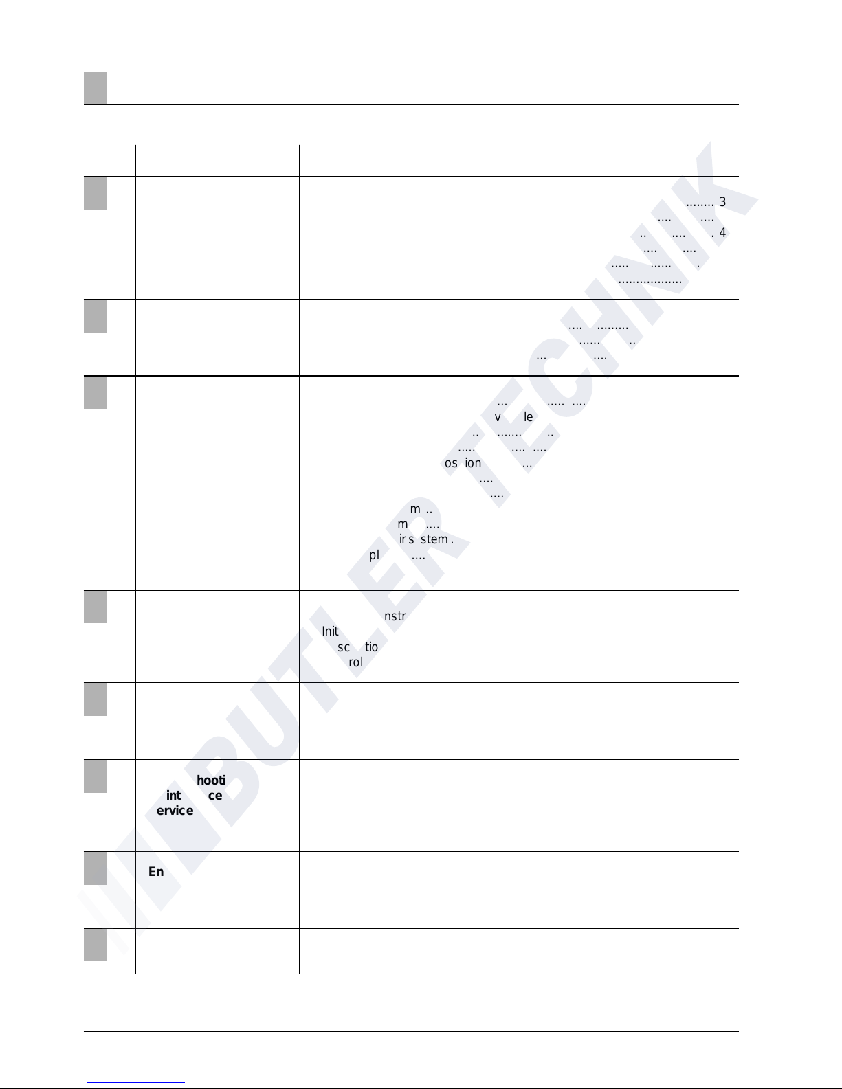
Contents
Chapter Title Contents
Introduction
Product information
Installation
Operation and function
• Concept of this manual......................................................................... 3
• Special text structure, presentation and picture symbols ................... 4
• Important information before starting work .......................................... 4
• Statutory regulations ....................................................................... 5, 6
• Safety instructions for installation and operation................................ 7
• Accident prevention ............................................................................. 7
• Scope of supply................................................................................ 8, 9
• Technical data .................................................................................... 10
• Main dimensions ................................................................................. 11
• Installation and location ..................................................................... 12
• Installing the 24 V heater in a vehicle for the transport
of dangerous goods ............................................................................ 12
• Installation location ...................................................................... 12, 13
• Possible installation positions............................................................. 14
• Mounting and fastening ...................................................................... 14
• Nameplate .......................................................................................... 15
• Heater air system ............................................................................... 16
• Exhaust system ................................................................................... 17
• Combustion air system........................................................................ 18
• Fuel supply ................................................................................. 19 – 23
• Operating instructions/ important information for operation .............. 24
• Initial commissioning ........................................................................... 24
• Description of functions...................................................................... 25
• Control and safety devices / EMERGENCY OFF ................................. 26
Electrical system
• Heater wiring ..................................................................................... 27
• Parts list for the circuit diagrams ................................................. 28, 29
• Circuit diagrams at the end of this manual
T r oubleshooting
Maintenance
Service
• In case of faults, please check the following points .......................... 30
• Troubleshooting procedure................................................................. 30
• Maintenance instructions ................................................................... 30
• Service ............................................................................................... 30
Environment
Lists
• List of key words .......................................................................... 32, 33
• List of abbreviations ........................................................................... 33
• Certification ........................................................................................ 31
• Disposal .............................................................................................. 31
• EU Declaration of Conformity.............................................................. 31
Page

3
1
Concept of this manual
Introduction
Introduction
Here you will find important introductory
information about installation of the heater
and about the structure of the manual.
Product information
Here you will find information about the scope
of supply, the technical data and the dimensions of the heater.
Installation
Here you will find important information
and instructions referring to installation of the
heater.
Operation and function
Here you will find information about the
operation and function of the heater.
This manual aims to support the service company installing the heater and to provide the user with all important information about the heater.
The manual has been divided into 8 chapters to make
it easier to find the corresponding information quickly.
Electric system
Here you will find information about the
electronic system and electronic components
of the heater.
T roubleshooting / maintenance / service
Here you will find information about any
necessary troubleshooting procedures, maintenance and the service hotline.
Environment
Here you will find information about certification and disposal of the heater together with
the EU Declaration of Conformity.
Lists
Here you will find the key word list and
abbreviations list.
6
7
8
1
2
3
4
5
4
1 Introduction
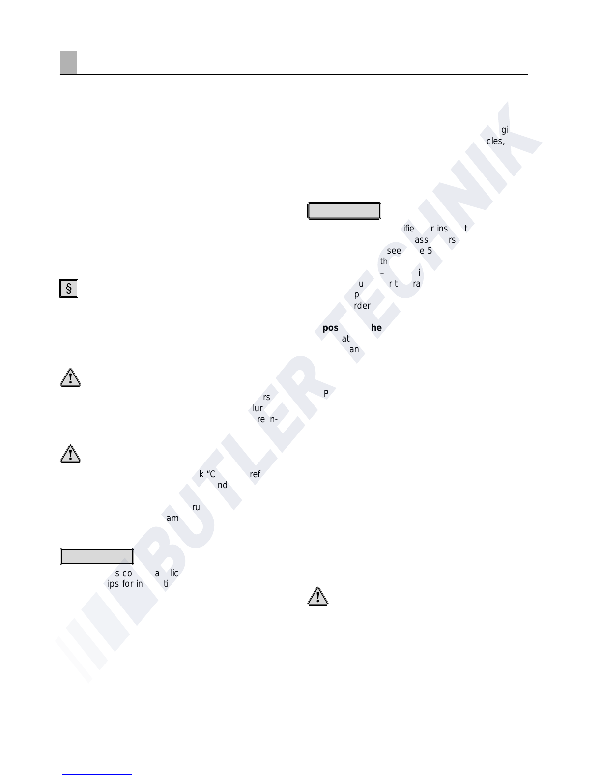
This manual uses special text structures and picture
symbols to emphasise different contents.
Please refer to the examples below for the corresponding meanings and associated actions.
Special structure and presentations
A dot (•) indicates a list which is started by a heading. If an indented dash (–) follows a dot, this list is
subordinate to the dot.
Picture symbols
Regulation!
This picture symbol with the remark “Regulation” refers to a statutory regulation. Failure to comply with
this regulation results in expiry of the type permit for
the heater and preclusion of any guarantee and liability claims on J. Eberspächer GmbH & Co. KG.
Danger!
This picture symbol with the remark “Danger!” refers
to the risk of a fatal danger to life and limb. Failure to
comply with these instructions can result in severe in-
juries under certain circumstances.
Caution!
This picture symbol with the remark “Caution!” refers
to a dangerous situation for a person and / or the product.
Failure to comply with these instructions can result in
injuries to people and/or damage to machinery.
These remarks contain application recommendations
and useful tips for installation of the heater.
Special text structure, presentation
and picture symbols
Range of application of the heater
The air heater operating independently of an engine is
intended for installation in the following vehicles,
depending on its heating output:
• Busses and coaches
• Truck cargo compartments
• Boats, ships and yachts
• The heater is not certified for installation in vehicle
compartments used by passengers (more than 8
seats). Exception see page 5: statutory regulations,
arrangement of the heater.
• Heater D 8 L C – 24 volt is allowed to be installed
in vehicles used for the transport of dangerous
goods as per ADR.
Here kit order no. 24 0189 00 00 00 is required.
Purpose of the heater
• Pre-heating, de-misting windows
• Heating and keeping the following warm:
– Driver and working cabs
– Freight compartments
– Ship’s cabins
– Passenger and crew compartments
On account of its functional purpose, the heater is
not permitted for the following applications:
• Long-term continuous operation, e.g. for preheating
and heating of:
– Residential rooms
– Garages
– Work huts, weekend homes and hunting huts
– Houseboats, etc.
• Heating or drying
– Living creatures (people or animals) by blowing
hot air directly at the subject
– Objects
– Blowing hot air into containers
Caution!
Safety instructions for application and
proper purpose!
• The heater must only be used and operated for the
range of application stated by the manufacturer in
compliance with the “Operating instructions”
included with every heater.
Important information before
starting work
Please note!
Please note!

5
The Federal Road Transport Directorate has issued an
"EC type approval" and an "EMC type approval" for the
heater for installation in motor vehicles and with the
following official type approval marks, noted on the
heater name plate.
Air heater 8 L EC- e1 00 0028
EMC- e1 021067
Statutory regulations
Statutory regulation!
Directive 2001 / 56 / EU of the European
Parliament and the Council
• Arrangement of the heater
– Parts of the structure and other components near
the heater must be protected from excess heat
exposure and possible contamination from fuel or
oil.
– The heater must not pose a fire hazard even
when it overheats.
This requirement is deemed to be fulfilled when
adequate clearance to all parts is observed
during installation, sufficient ventilation is provided
and fire-proof materials or heat plates are used.
– The heater must not be mounted in the passenger
compartment of vehicles in class M
2
and M3.
But a heater in a hermetically sealed enclosure
which otherwise complies with the conditions
stated above may be used.
– The factory nameplate or duplicate must be
affixed so that it can still be easily read when the
heater is installed in the vehicle.
– All appropriate precautions must be taken when
arranging the heater to minimise the risk of
injuries to persons or damage to other property.
• Operating status display
– A clearly visible operating display in the user’s
field of vision must indicate when the heater is
switched on and off.
• Fuel supply
– The fuel intake connection must not be located in
the passenger compartment and must be sealed
with a properly closing lid to prevent any fuel
leaks.
– In heaters for liquid fuel where the heater fuel is
separate from the vehicle fuel, the type of fuel
and intake connection must be clearly identified.
– A warning sign is to be fixed to the intake
connection indicating that the heater must be
switched off before refuelling.
• Exhaust system
– The exhaust outlet must be arranged so as to
prevent any penetration of exhaust fumes into the
vehicle interior through the ventilation system,
warm air intakes or open windows.
• Combustion air intake
– The air for the heater combustion chamber must
not be sucked in from the passenger compartmentof the vehicle.
– The air intake must be arranged or protected in
such a way that it cannot be blocked by other
objects.
• Heater air intake
– The heater air supply must consist of fresh air or
circulated air and be sucked in from a clean area
not contaminated by exhaust fumes of the drive
machine, the combustion heater or any other
source in the vehicle.
– The intake pipe must be protected by a grid or
other suitable means.
• Hot air outlet
– The hot air pipes within the vehicle must be
arranged or protected in such a way that there is
no risk of injury or damage if they are touched.
– The air outlet must be arranged or protected in such
a way that it cannot be blocked by any objects.
Statutory regulation!
Mounting the heater in a vehicle for the transport of
dangerous goods as per ADR
• When the heater is to be installed in vehicles for the
transport of dangerous goods, the regulations of
ADR must also be observed (see page 6).
1 Introduction

6
1 Introduction
• Compliance with the statutory regulations, the
additional regulations and safety instructions is
prerequisite for guarantee and liability claims.
Failure to comply with the statutory regulations and
safety instructions and incorrect repairs even when
using original spare parts make the guarantee null
and void and preclude any liability for
J. Eberspächer GmbH & Co. KG.
• Subsequent installation of this heater must comply
with these installation instructions.
• The statutory regulations are binding and must also
be observed in countries which do not have any
special regulations.
• When the heater is to be installed in vehicles not
subject to the German Ordinance for the Registration of Motor Vehicles (StVZO), for example
ships, the specially valid regulations and
installation instructions for these special
applications must be observed.
• Installation of the heater in special vehicles must
comply with the regulations applying to such
vehicles.
• Other installation requirements are contained in the
corresponding sections of this manual.
Statutory Regulations
Additional regulations for certain vehicles
named in Directive 94 / 55 / EC (ADR
Framework Directive)
Scope
This appendix applies to vehicles for which the special
provisions of Directive 94 / 55 / EC apply to combustion heaters and their installation.
Definition of terms used
For the purposes of this appendix, the vehicle
designations "EX / II", "EX / III", "A T", "FL" and "OX"
according to Chapter 9.1 of Annex B of Directive 94 /
55 / EC are used.
Technical regulations
General provisions (EX / II, EX / III, AT, FL and OX
vehicles)
Avoid heating and ignition
The combustion heaters and their exhaust gas routing
shall be designed, located, protected or covered so
as to prevent any unacceptable risk of heating or
ignition of the load. This requirement shall be
considered as fulfilled if the fuel tank and the exhaust
system of the appliance conform to provisions in
3.1.1.1 and 3.1.1.2. Compliance with these
regulations shall be checked in the complete vehicle.
Fuel tanks
Fuel tanks for supplying the heater shall conform to
the following regulations:
• In the event of any leakage, the fuel shall drain to
the ground without coming into contact with hot
parts of the vehicle or the load;
• fuel tanks containing petrol shall be equipped with
an effective flame trap at the filler opening or with a
closure enabling the opening to be kept
hermetically sealed.
Exhaust system and exhaust pipe layout
The exhaust system as well as the exhaust pipes shall
laid out or protected to avoid any danger to the load
through heating or ignition. Parts of the exhaust
system situated directly below the fuel tank (diesel)
shall have a clearance of at least 100 mm or be
protected by a thermal shield.
Switching on the combustion heater
The combustion heater may only be switched on
manually. Automatic switching on via a programmable
switch is not permitted.
EX / II and EX / III vehicles
Combustion heaters for gaseous fuels are not
permitted.
FL vehicles
Combustion heaters must be able to be taken out of
service/disabled at least by the methods described in
the following:
a) Switching off manually in the driver's cabin
b) Switching off the vehicle's engine; in this case the
heater may be manually switched back on by the
vehicle driver;
c) Starting up of a feed pump installed in the vehicle
for the dangerous goods carried.
Combustion heater after-run
After-running of the switched off combustion heater is
permitted. In the cases named in the "FL vehicles"
paragraph under letters b) and c) the supply of
combustion air must be interrupted by suitable means
after a maximum after-run period of 40 seconds. Only
combustion heaters whose heat exchangers are
verifiably not damaged by the reduced after-run period
of 40 seconds beyond their usual use period may be
used.
Please note!

7
Safety instructions for installation
and operation
Danger!
Risk of injury, fire and poisoning!
• The heater must only be started up when the
maintenance flap is closed and the outlet hood is
mounted in position.
• The maintenance flap must not be opened during
operation.
• Disconnect the vehicle battery before commencing
any kind of work.
• Before working on the heater, switch the heater off
and let all hot parts cool down.
• The heater must not be operated in closed rooms,
e.g. in the garage or in a multi-storey car park.
• Adjustable hot air outlets must always be adjusted
so that they cannot blow hot air directly at living
creatures (people, animals) or objects sensitive to
temperature (loose and / or fastened).
Caution!
Safety instructions for installation and operation!
• The year of initial commissioning must be marked on
the nameplate.
• The heat exchanger of air heaters is a component
subject to high thermal loads which must be
replaced 10 years after initial commissioning of the
heater. In addition, the installation date must be
entered on the plate “original spare part” enclosed
with the heat exchanger must. Then affix the plate
next to the nameplate on the heater.
• The heater must only be installed by a JE partner
authorised by the manufacturer according to the
instructions in this manual and possibly according to
special installation recommendations; the same
applies to any repairs to be carried out in the case
or repairs or guarantee claims.
• Only the control elements approved by Eberspächer
must be used to operate the heater. The use of
other control elements can cause malfunctions.
• Repairs by unauthorised third-parties or with not
original spare parts are dangerous and therefore not
allowed. They result in expiry of the type permit of
the heater; consequently, when installed in motor
vehicles they can cause expiry of the vehicle
operating licence.
• The following measures are not allowed:
– Changes to components relevant to the heater.
– Use of third-party components not approved by
Eberspächer.
1 Introduction
– Nonconformities in installation or operation from
the statutory regulations, safety instructions or
specifications relevant to safe operation as stated
in the installation instructions and operating
instructions. This applies in particular to the
electrical wiring, fuel supply, combustion air
system and exhaust system.
• Only original accessories and original spare parts
must be used during installation or repairs.
• When carrying out electric welding on the vehicle,
the plus pole cable at the battery should be
disconnected and placed at ground to protect the
controller.
• The heater must not be operated where there is a
risk of an accumulation of flammable vapours or
dust, for example close to
– fuel depot
– coal depot
– wood depot
– grain depots etc.
• The heater must be switched off when refuelling.
• When the heater is mounted in a safety housing
etc., the installation compartment of the heater is
not a stowage compartment and must be kept
clear.
In particular fuel canisters, oil cans, spray cans,
gas cartridges, fire extinguishers, cleaning rags,
items of clothing, paper etc. must not be stored or
transported on or next to the heater.
• Defect fuses must only be replaced by fuses with
the prescribed rating.
• If fuel leaks from the heater fuel system, arrange
for the damage to be repaired immediately by a JE
service partner.
• After-running of the heater must not be interrupted
prematurely e.g. by pressing the battery
disconnecting switch, apart from in the case of an
emergency stop.
Accident prevention
General accident prevention regulations and the
corresponding workshop and operation safety
instructions are to be observed.

8
Product information2
Scope of supply for air heater D 8 L C
Quantity / Designation Order number
1 8 L – 12 Volt 25 1890 00 00 00
1 8 L – 24 Volt 25 1891 00 00 00
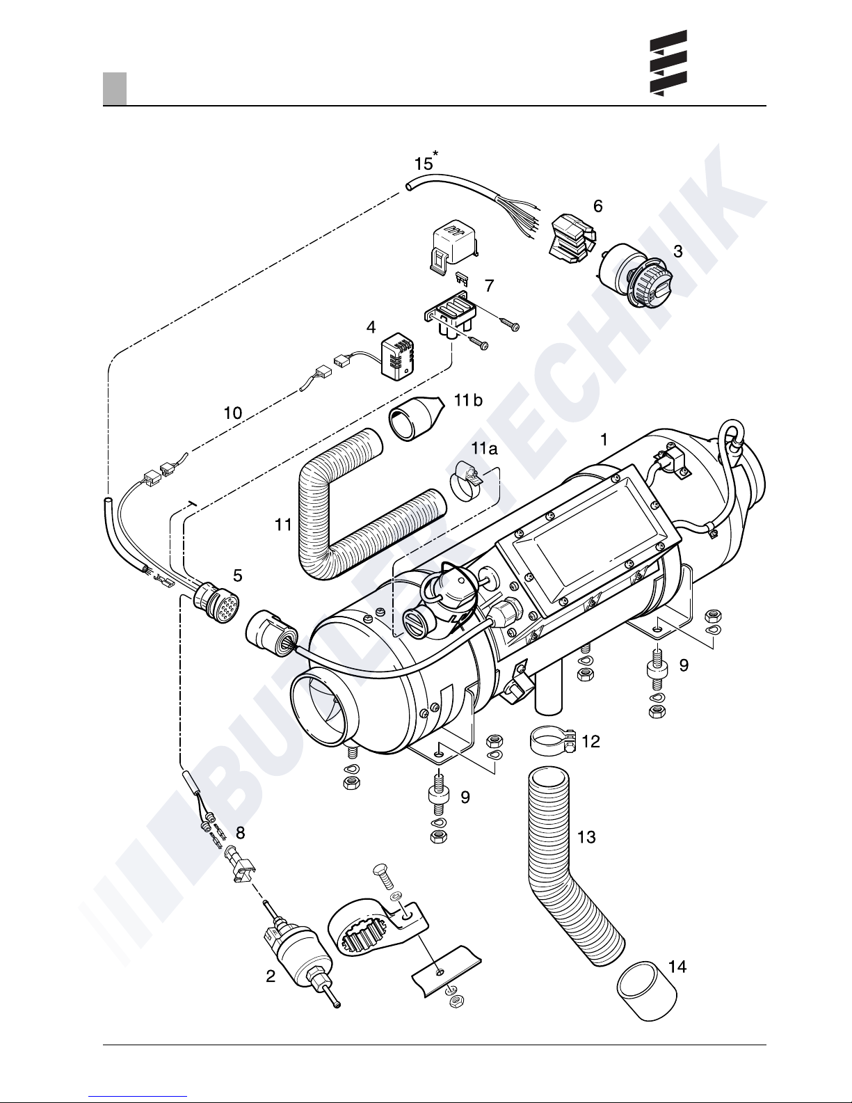
Scope of supply
Basic heater, pre-mounted
1 D 8 L C – 12 V
1 D 8 L C – 24 V
1 Dosing pump with mounted fuel filter
and holder
1 Control element
1 External temperature sensor
1 Cable harness with connection parts
1 Plug-in sleeve housing with connection parts
1 Flat fuse with fuse holder
2 Push-on contact with cable bushing
4 Metal rubber anti-vibration pads
with fastening parts
To be ordered separately:
1 Cable harness
temperature sensor 25 1482 89 40 00
1 Combustion air hose 10 2114 25 00 00
1 Hose clip 10 2064 03 20 50
1 End sleeve
for combustion air hose 25 1480 89 04 00
1 Flexible exhaust pipe LW 42 360 61 381
1 Pipe clip
for flexible exhaust pipe LW 42 152 10 064
1 End sleeve
for flexible exhaust pipe LW 42 22 1000 40 02 00
1 Exhaust pipe (rigid) 047 05 044
1* Cable harness, control element
* Made in-house with the 5 m long lead harness
(Order No. 22 1000 30 03 00). Disconnect the
existing connector from the cable loom. Prepare the
cable strands for installation of the push-on sleeves
and attach the push-on sleeves. The push-on
sleeves are included in the scope of supply.
Connect the cable loom at the cable loom connector (5) and at the push-on sleeve housing of the
control unit (6) in accordance with the circuit
diagrams at the end of the document.
• Parts without picture number are small parts and
packed in a bag.
• Please consult the additional parts catalogue if
any other parts are required for installation.
Picture-No. / Designation
1 Basic heater, pre-mounted
2 Dosing pump with mounted fuel filter
and holder
3 Control element
4 External temperature sensor
5 Cable harness with connection parts
6 Plug-in sleeve housing with connection parts
7 Flat fuse with fuse holder
8 Plug-in sleeve housing with plug-in sleeve
and seals
9 Metal rubber anti-vibration pads with
fastening parts
10 Cable harness temperature sensor
11 Combustion air hose
11a Hose clip
11 b End sleeve
12 Pipe clip for exhaust pipe
13 Flexible exhaust pipe
14 End sleeve exhaust pipe
15* Cable harness, control element
Parts list for the picture
“Scope of supply” on page 9
Please note!
9
Product information2
Scope of supply
10
Caution!
Safety instructions for technical data!
Failure to comply with the technical data
can result in malfunctions.
Provided no limit values are given, the technical data
listed is subject to the tolerances usually applicable
to heaters of ±10% for nominal voltage, ambient temperature 20 °C and reference altitude Esslingen.
2 Product information
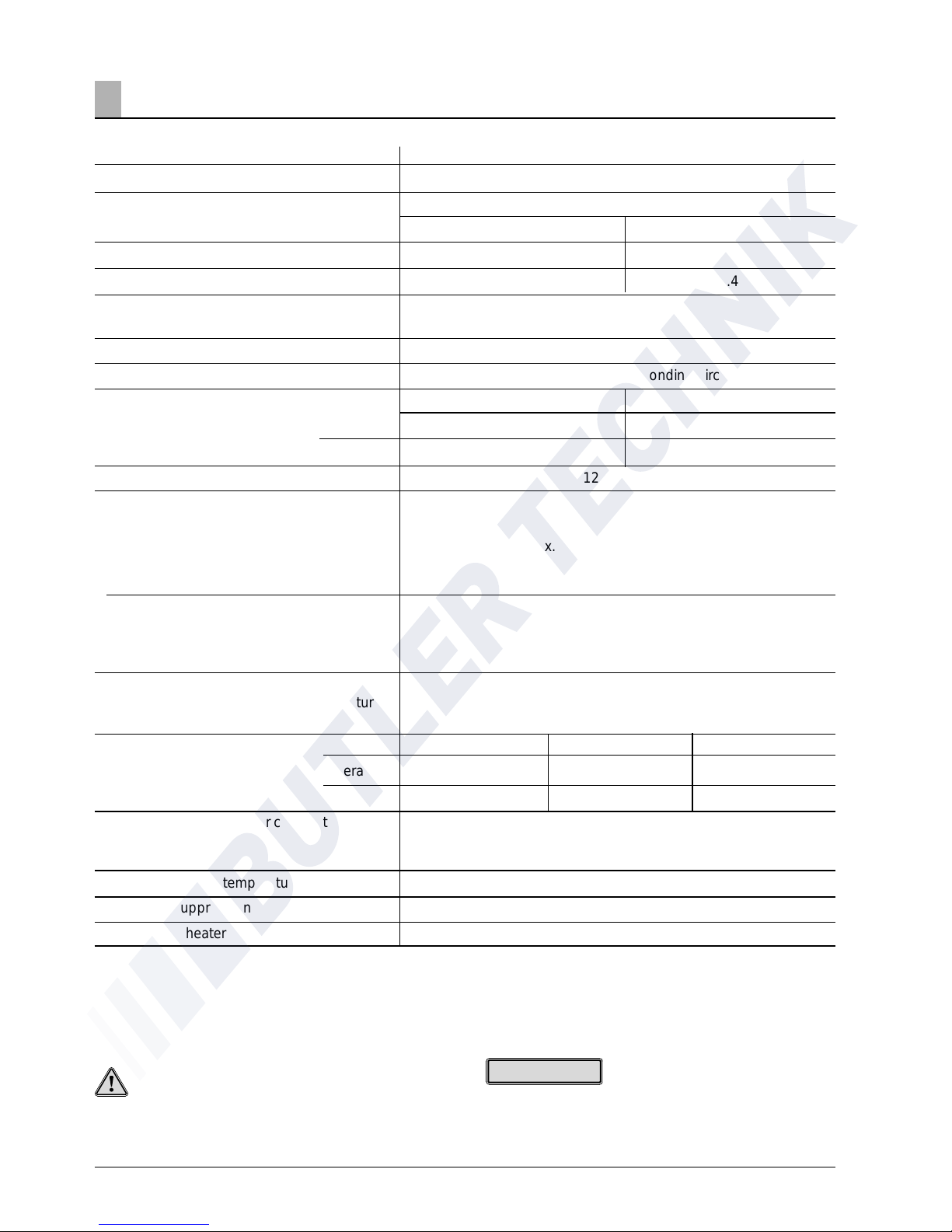
Technical data
Heater
Heating medium
Control of the heat flow
Heat flow (watt)
Fuel consumption (l/h)
Heater air flow rate
without counterpressure (kg/h)
Heater code
Fan mode
Electr. power (watt)
in operation
at start
Rated voltage
Operating range
Lower voltage limit:
An undervoltage protection in the controller
switches the heater off on reaching approx.
10 Volt resp. 20 Volt.
Upper voltage limit:
An uppervoltage protection in the controller
switches the heater off on reaching approx.
14 Volt resp. 28 Volt.
Fuel
“Fuel quality“ and “Fuel at low temperature“
see operating instructions page 23.
Tolerable operating temperature
Operation
Storage
Noise emission – passenger compartment
Maximum air intake temperature
Interference suppression
Weight (basic heater without mounted parts)
D 8 L C
Air
Stage
Large Small
8000 3500
1.05 0.4
310
8
possible with corresponding circuit
at 12 volt at 24 volt
115 115
330 380
12 or 24 Volt
approx. 10 volt resp. approx. 20 Volt
approx. 14 volt resp. approx. 28 Volt
Commercially available diesel fuel (DIN EN 590)
Heater Controller Dosing pump
–40 °C to +60 °C –35 °C to +60 °C –35 °C tos +60 °C
–40 °C to +70 °C –35 °C to +70 °C –35 °C to +60 °C
The maximum noise level pressure is <60 db (A), measured in
the operating mode power stage “Large“, as per 3. GSGV resp.
DIN 45 635 – part 1.
+60 °C
Remote (other measures possible)
approx. 14 kg
Please note!
11
2 Product information
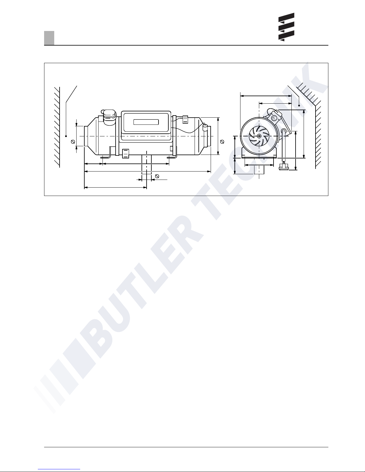
Main dimensions
1 Minimum installation clearance (space) for intake of heater air.
2 Minimum installation space (free space) for opening the lid
and removing the glow plug and controller.
-
+
1
100
103
370
653
42
190
165
260
110
80
145
1m
250
2
1
323
+ 1,5
0
-
+
1

12
Location
Installation position in a coach or bus.
The heater is installed in a coach or bus preferably in
a separate, splash-proof position outside the passenger compartment.
If there is no space available outside the passenger
compartment, the heater can also be installed in a
3
Installation
Installation and location
Installation in the driver's cab or passenger compartment of coaches and busses with more than 9 seats
is not allowed. Exception see page 5, statutory regulations, arrangement of the heater.
The electronic control is integrated in the heater
which makes wiring during installation much easier.
Fasten the heater with both consoles and 4 anti-vibration pads on the floor of the vehicle.
The heater may be installed in vehicles used for the
transport of dangerous goods as per ADR.
Here kit order no. 24 2189 00 00 00 is required.
Installing the 24 V heater in a vehicle for
the transport of dangerous goods as per
ADR
• When fitting the heater, ensure there is sufficient
space for heater air intake and for removing the
glow plug and controller (see page 11, main dimensions).
• The regulations and safety instructions to be
observed for this chapter are on page 4 – 7.
• For installation of the heater in vehicles for the
transport of dangerous goods, the regulations of
ADR must be observed.
• Detailed information about the ADR regulations is
contained in leaflet no. 25 2161 95 15 80.
box complying with the statutory regulations (see
page 5) which has been sealed off from the passenger
compartment.
The box must be ventilated to the outside. Breakthroughs to the outside must be splash-proof.
1 Heater
2 Dosing pump
3 Heater air supply (air circulation)
4 Heater air outlet
5 Fuel tank
6 Exhaust pipe
7 Combustion air supply
8 Control element
U Air circulation
V Combustion air
W Hot air
A Exhaust
Please note!
Please note!
13
3
Installation
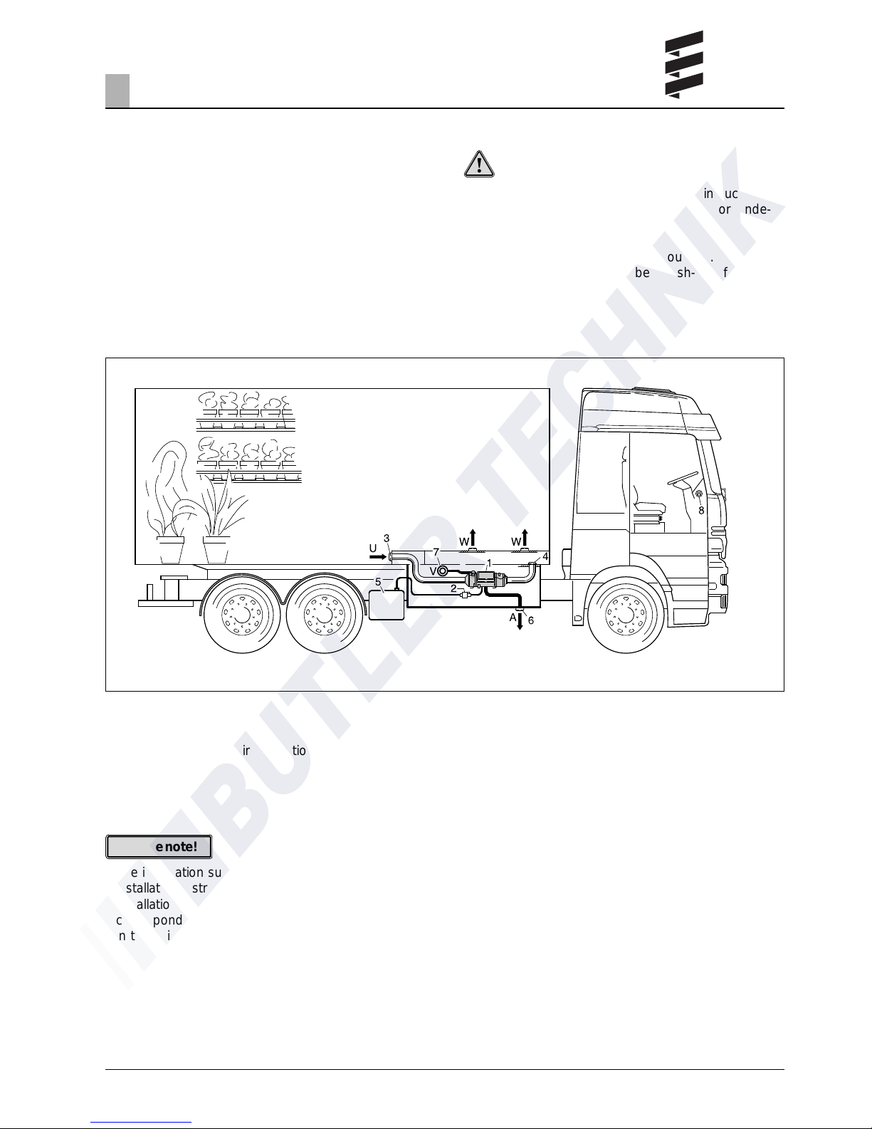
Installation position in a truck cargo compartment
For cargo compartment heating, the heater is fastened in a splash-proof position on the vehicle preferably in a box outside the cargo compartment.
If no suitable place is available outside the cargo
compartment, then the heater can also be fastened
to the floor of the cargo compartment in a suitable
position.
• The installation suggestions made in the
installation instructions are just examples. Other
installation locations are possible, as long as they
correspond to the installation requirements stated
in these instructions.
• Other installation information (e.g. for boats and
ships) is available from the manufacturer on
request.
• Observe the tolerable installation position together
with the operating and storage temperatures.
Location
Caution!
The heater air outlets must be arranged in such a
way that the flow of hot air is not impaired or hinde-
red by the load.
The box must be ventilated to the outside. Breakthroughs to the outside must be splash-proof.
1 Heater
2 Dosing pump
3 Heater air supply (air circulation)
4 Heater air outlet
5 Fuel tank
6 Exhaust pipe
7 Combustion air supply
8 Control element
U Air circulation
V Combustion air
W Hot air
A Exhaust
Please note!
14
Mounting and fastening
The heater can be fastened to the floor of the vehicle
or to a vertical vehicle wall using the anti-vibration
pads.
Drill the 4 holes for the two fastening brackets and
the breakthrough for the exhaust pipe in the floor or
wall of the vehicle.
3
Installation
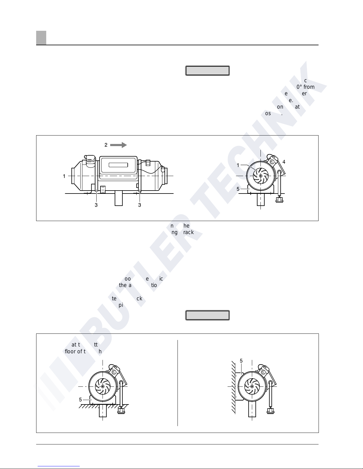
Possible installation positions
The heater must be installed in its normal position, as
shown in the drawing.
In heating mode, it is possible for the heater's position to deviate by up to ± 15° in all directions without
impairing the heater function, for example when the
vehicle is on a slope or when the heater is fitted on
board a boat.
Normal position horizontal (exhaust connection downwards)
1 Heater air intake opening (impeller)
2 Direction of flow
3 Clamping strap
After loosening the clamping straps c , the fastening
brackets e can be turned around the horizontal axis
to adapt to the installation conditions.
If necessary, the fastening points should be reinforced!
Apart from this, after the heater has started up, continuous operation in a position deviating by ± 30° from
the normal position is possible in the case of operating positions which change at short notice.
The heater cannot operate if its position deviates by
more than 30° from the normal position.
Fastening at the bottom
(on the floor of the vehicle)
Fastening to the side
(to the wall of the vehicle)
Comply with the prescribed installation position!
4 Position of the glow plug
5 Fastening bracket
Please note!
Please note!
15
3
Installation
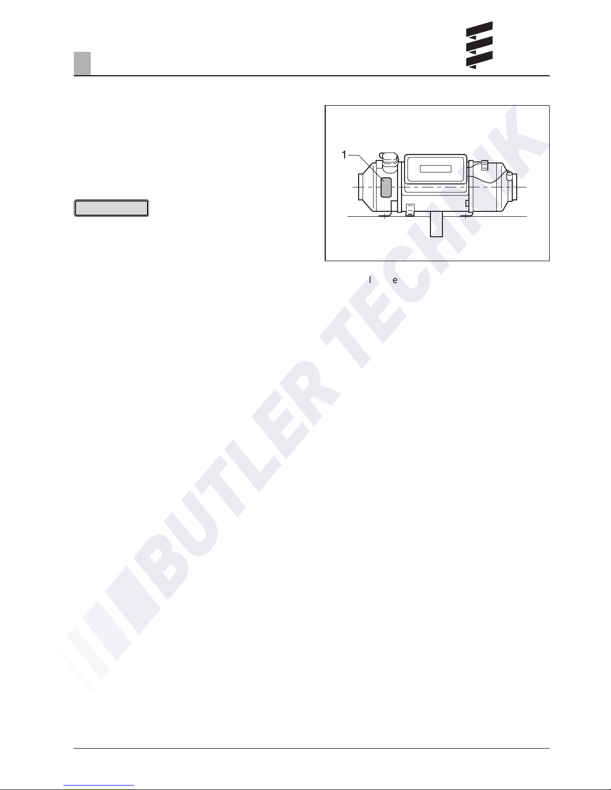
Nameplate
The nameplate is fastened in a clearly visible position
to the jacket of the heater.
The second nameplate (duplicate) is included in the
scope of supply of the heater and can be adhered as
required in a clearly visible position on or near the
heater.
The regulations and safety instructions to be observed
for this chapter are stated on page 4 – 7.
1 Original nameplate
Please note!
 Loading...