

Page 1
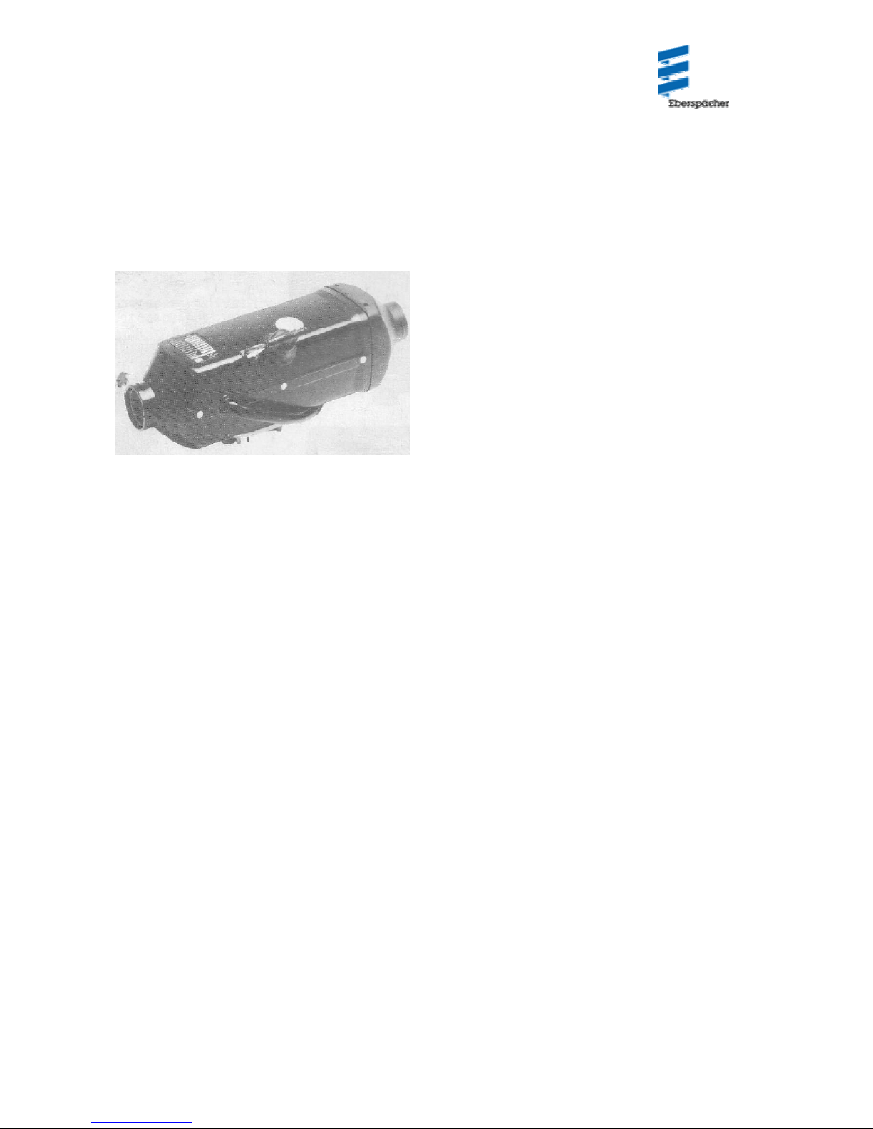
Air heaters B1L/D1L
Technical Description
Installation instructions
Operating Instructions
Air heaters independent of engine
B1L for petrol
D 1 L for diesel
Specifications
Heating medium Air
Hot air throughput
(without counter-pressure)
Heating capacity
Fuel B1L: Gasoline,
(see also page 10) (Commercial grade)
Fuel consumption
Rated voltage 12 V or 24 V
Operating range:
Lower voltage limits
Upper voltage limit
Electrical power B1L
consumption
1)
100 kg/h ±10
1)
1800 W ± 10 11/0
D1L: Diesel fuel,
(Commercial grade)
1)
B1L: 0.24 I/h ± 5%
D1L: 0.21 1/h ± 5
2)
10 V or 20 V
3)
14 V or 28 V
1)
at start 200W±10%
operating 40 W ± 10
D 1 L
at start 12 V = 260 W ± 10
24V=500W±10%
operating 40 VV ±10%
J. Eberspacher
Eberspacharstr. 24
D-7300 Essllngen
Telefon (zentral)
(0711) 31 09-0
Telefax
(0711) 3109-500
B1L Cat. no.
Basic heater
with standard equipment 12V 20 1590 05 00 00
Universal installation kit 20 1575 80 00 00
D 1 L Cat. no.
Basic heater
with standard equipment 12 V 25 1384 05 00 00 24V 25
1385 05 00 00
12V 25 1637 05 00004)
24 V 25 1638 05 00004)
Universal installation kit 20 1575 80 00 00
Control elements (to be ordered sepa ra tely, see page 2). See
Additional Equipment Catalog for other accessories.
Ventilation Possible with suitable circuits
Degree of radio inter- Remote; additional
ference suppression interference suppression
measures possible
Weight approx.. 3 kg
1)
at rate voltage
2)
an undervoltage safety device built into the control unit
switches off the heaters when at approx.. 10.5 V and 21 V
respectively.
3)
an overvoltage safety device built into the cont ro l
unit switches off the heaters when at approx. 15 V and 30 V
respectively.
4)
with glow plug current regulator
Page 2

Contents Page
Scope of delivery/Cat. No 2,3
Official regulations 4
Installation instructions 4
Typical installation s/installation location 4, 5
Installing the heater 5
Principal dimensions 5
Permissible installation position s/Fa sten i ng metho d s 6
Running the heating air/det e rm inat i on of ratin g 7
Running the combustion air 8
Running the exhaust 8
Fuel supply 9, 10
Fuel at low temperatures 10
Electrics/Wiring diagrams 11-16
Description of operation 17, 18
Malfunctions 18
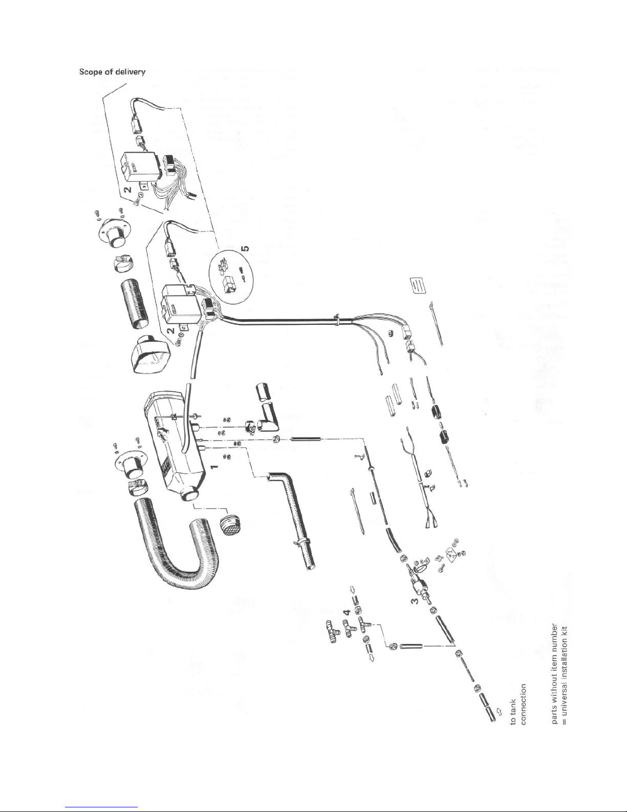
Scope of delivery:
Item Qty. Design/Cat. No
B 1 L
Basic heater with standard equipment
1 - 4 1 12 V 20 1590 05 00 00
(Optional control elements)
Standard equipment comprises:
1 1 Basic heater 20 1593 01 (12 V)
(not available alone)
2 1 Control unit
3 1 Fuel metering pump
with built-in fuel filter
4 3 T-piece6x6,8x6,12x6
D 1 L
1-4 1 Basic heater with standard equipment
12 V 25 1384 05 00 00
24 V 25 1385 05 00 00
12 V 25 1637 05 00 00
24 V 25 1638 05 00 00
Standard equipment comprises:
1 1 Basic heater
25 1384 01 (12V), 25 1385 01 (24V)
25 163701 (12V), 25 1638 01 (24V)
(not available alone)
2 1 Control unit
3 1 Fuel metering pump
with built-in fuel filter
4 3 T-piece 6 x 6, 8 x 6, 1 2 x 6
and additionally to be ordered for 1131 L and D 1 L
5 1 Set of connectors 25 1 380 89 05 00
- 1 Universal install kit 20 1 575 80 00 00
Control elements, optional
Timer
Cat. No.
12V 25 1482 89 25 00
24V 251483891000
Fasteners
(only required for installation
with screen)
Cat. No.
2514827001 00
Timer with fasteners
Cat. No.
12V 25 1482 89 19 00
24V 25 1483 89 02 00
Universal switch
Cat. No.
25 1 380 89 04 00
Bulb
12V 207 00 005
24V 207 00 006
Room thermostat
Cat. No.
black 25 1 557 8001 00
brown 25 1 557 8007 00
Page 3
3
Page 4
Approval, official regulations, general
1. For vehicles reg istered in West Germ any (subject to the road traffic
regulations StVZO), the heaters are a pproved by the Federal Motor
Vehicle Office and receive an official test symbol (131 L ~ S 133, D1
L A V S 146) indicate d on the name plate).
The year of first operation is a requirement of German approval not
representing a model number.
2.If the heater is installed in special-purpose vehicles (e. g. vehicles
transporting dangerous cargoes), the regulations applicable to such
vehicles must be observed.
3. The heater must not be operated in closed rooms, e.g. garages.
The heater must always be switched off when the petrol tank is to
be filled.
4. The heaters must be installed by a workshop approved by the
manufacturer and in compliance with the installation instructions.
5. The heaters may only be used for the purpose specified by the
manufacturer and in compliance with the operating instructions
supplied with every heater.
Operating the heater is not permitted where inflammable vapours or
dust can build up (e.g. near fuel, coal or sawdust stores, grain silos
etc.).
Spray cans and gas cartridges in the vehicle must be kept out of the
heating air current.
6. The proposed installations in the installation instructions are only
examples. Other installation locations are also permissible, provided
they comply with the general installation requirements: the
manufacturer should be consulted if necessary- In all other respects,
differences from the installation instructions, particularly with regard
to wiring (wiring diagrams), fuel supply, combustion air and exhaust
ducts, and use of operating and control elements not supplied by the
manufacturer, are only permissible with the written approval of the
manufacturer. Failing that, the manufacturer's warranty is null and
void for the entire heater system, as is the general operating permit.
7. Every combustion process generates exhaust gas, which has toxic
constituents. Because of this and the high temperatures generated,
the exhaust duct must comply without fail with the installation
instructions. Failure to comply with the instructions or operation of
the heater in closed rooms (garages) harbours the risk of poisoning.
8. When the heater or the heating system is damaged, an authorized
workshop must be called in to repair the damage in an expert
manner and using genuine spare parts.
Makeshift repairs (on one's own initiative) or the use of non-genuine
spare parts are dangerous, and therefore not permitted. When
carried out in cars, they invalidate the general design approval of the
heater and consequently the general permit of the vehicle.
9. The warranty conditions are set forth in the heater booklet given to
you by the after-sales service workshop when the heater is installed.
Only our warranty c onditions shall app ly.
Installation Instructions
The suggestions put forward in these installation instructions are only examples. Possibilities other than those illustrated (e. g.
with regard to the choice of installation location, means of running air) ar e a lso permissible, provided they meet the requirements
of the West German road traffic regulations (StVZO), and if necessary after consultation with the manufacturer.
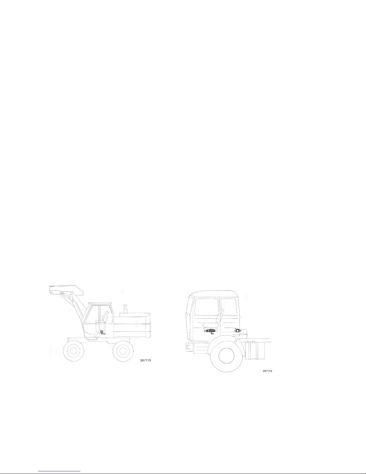
Typical installations/installation location
In excavator: In truck:
D 1 L
in the cab D 1 L
1. on the rear wall of the cab
2, under the seat of the driver
4
Page 5
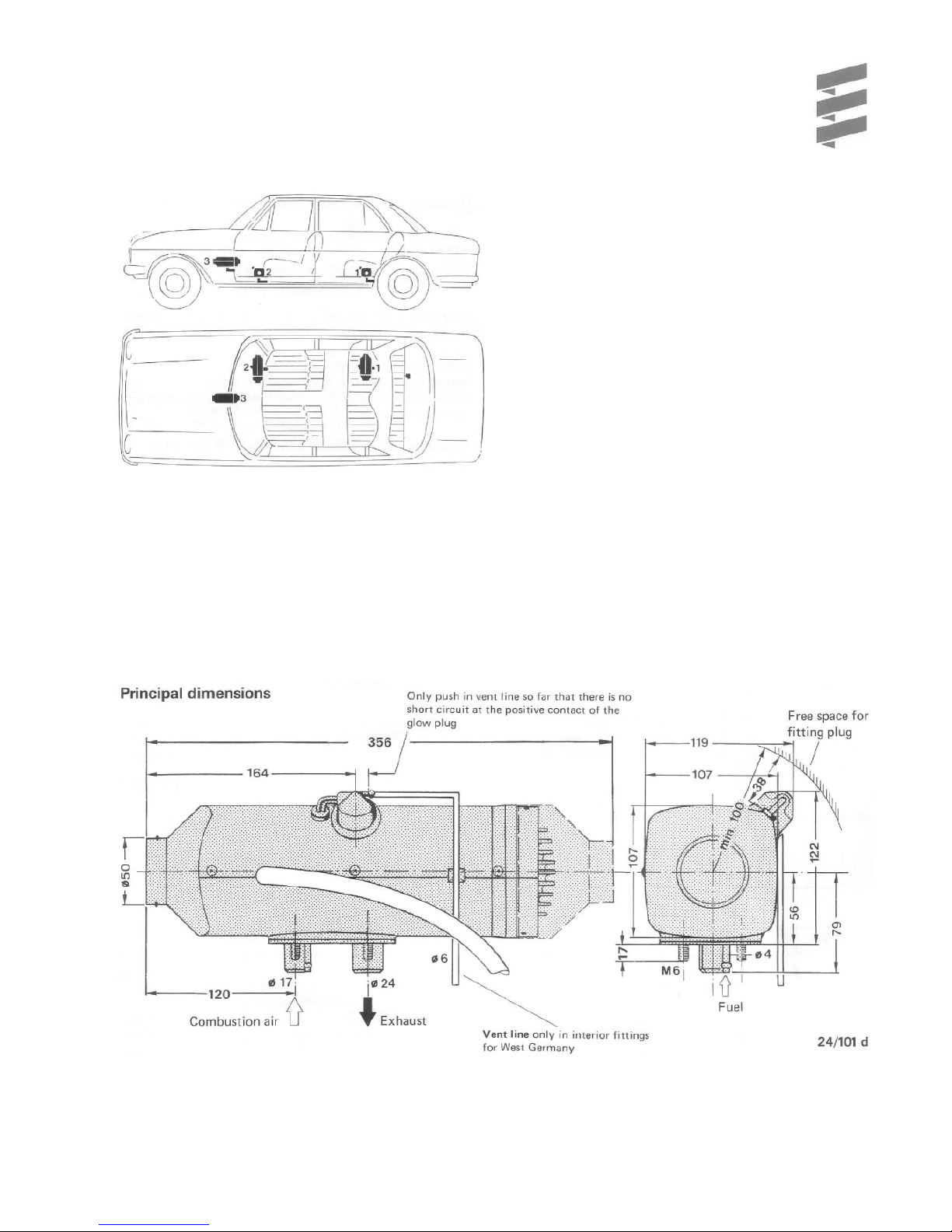
B 1 L/D 1 L
in vehicle interior
1.Heater under rear seat, inside or outside
2. Heater in front of passenger seat.
3. Heater on center console
Installing the heate r
The B 3 L and D 3 L heaters are suitable and approved for
installation in vehicle areas used by passengers.
In the case of installation in passe nger a re as, the exha u st,
combustion air and fuel lines in these areas must no t have
any detachable connections and must be splash-water-tight
at the penetrations to the outside.
For this reason, the heater must be mounted by its base on
an outside panel of the vehicle or on its floor, using the seal
seated on the base.
The factory plate must be clearly visible even when
installed.
If necessary a second fa ctory plate (duplicate) may b e
affixed, with the same information as the original, to a place
on the heater clearly visible after installation, or to a cover
placed in front of the heat er. A second plate is not if the
original is visible after removal of a cover without the
necessary, aid of tools.
5
Page 6

Fastening to the vehicle wall/floor
Make penetrations in accordance with the template pattern.
Templet pattern
The holes for the 8 mm dia. vent lines and for the 10.5
mm-dia. metering pump/control unit cable are not
included in the template pattern, and must be drilled to
suit the installation arrangement.
The mating surface for the hea ter base must be smooth.
To drill the penetrations and if necessary to smooth the
mating surface, a speci al tool is available from the
Special tool
In general the heater should be installed in standard position,
as shown.
If this is not feasible, please consult the manufacturer.
During starting an thermostatic operation a heater installed in
the standard position may deviate, due to the inclination of the
vehicle during motion, from this standard position up to ± 150 in
both axes.
Continuous heating operation after starting is even possible at a
deviation from standard position of up to ± 300.
With deviations exceeding ± 300 a reliable continuous heating
operation is no longer possible. However, this does not lead to
damage of the heater if the deviation occurs only for a short
interval.
Important: The plug connection piece must always face
upwards.
*This must be kept free. Ch eck for free running of fan wheel
If the mating surface sheet is too thin (criterion: less than 1.5
mm), a reinforcing plate - Cat. No. 20 1577 89 00 03 - can be
installed additionally on the outside.
6
Page 7

Item Designation Component Cat. No rating
1 Protective grid 0.4 20 1465 89 05 00
2 Connection piece, 50 mm dia. 0.4 20 1575 80 08 01
3 Hose clip, 50 - 70 mm dia - 2064 05 00 70
4 Flex. pipe, 50 mm dia. lin. m. 1.0 per m 10 2114 29 00 00
5 Protective grid, 50 mm dia. 0.1 20 1575 89 20 00
6 Hood 0 20 1465 89 00 01
7 Air outlet, rotatable, 50 mm dia. 1.25 20 1575 80 08 00
- 90° bend of flex pipe, 50 mm dia. 0.4
Do not connect too many components. The sum of the component ratings may not exceed the heater rating. See Additional
Equipment Catalog for further parts.
Item Designation Component Cat. No rating
1 Protective grid 0.4 20 1465 89 05 00
2 Connection piece, 50 mm dia. 0.4 20 1575 80 08 01
3 0.3 flexible pipe, 50 mm dia. 0.3 20 2114 29 00 00
4 1.0 m flexible pipe, 50 mm dia. 1.0 20 2114 29 00 00
5 Reduction hood, 50 mm dia.straight 0.0 20 1465 89 00 01
6 2 x 90° bends of flexible pipe 0.8
(0.4 rating for each)
7 Exhauster, rotatable 1.25 20 1575 80 08 00
Sum of component ratings 4.15
The sum of the component ratings does not exceed the heater
rating of 10, installation is therefor permissible.
When checking an installation, the average outlet temperature
should not at the outlet point significantly exceed 110°C with
an intake temperature of 20°C. This will ensure that the safety
thermal cutout switch will not respond under normal
operating conditions.
Heating air intake openings shall be arranged in such a
manner that exhaust from the vehicle's engine and from the
heater cannot be expected to be sucked in under normal
operating conditions, and the heating air cannot be
contaminated.
When operating as a recirculating heater, locate the inlet for
the heating air in such a way that the outflowing hot air cannot
be sucked directly in again.
7
Page 8

Running the combu stion air/Running the exhaust
Permissible diameters, lengt hs, bend s of combu s tion air an d exha u st lin es.
Measurements in millimeters
Permissible blend Exhaust lines
Exhaust line: max. 180
0
B 1 L max. 500 mm long
Combustion air line: max. 1800 D 1 L max. 1000 mm long
must not be exceeded.
The scope of delivery includes an exhaust pipe, 270 mm long,
with 900 bend, and a combustion air tube, 500 mm long, with
90° bend.
These can be shortened as required. Longer pipes are available as given in the Additional Equipment Catalog.
Additional noise suppression is possi bl e by instal l ing an exhaust silencer (see chapter "Exhaust Parts" in the Additional
Equipment Catalog). The permissible length of the exhaust line
is reduced here by the length of the exhaust silencer.
The combustion air must be sucked in from the outside, not
from the passenger compartment or trunk.
Do not install the intake opening facing the slipstream, but run
it in such a manner that dirt and snow cannot enter and that
any water which does enter can flow out.
Exhaust lines must not project beyond the sides of the vehicle.
They must be laid either with a slight slope or with 5 mm dia.
holes at the lowest points for draining off condensate.
Arrange the exhaust outlet and t he combustion air opening
such that the exhaust cannot be sucked back in directly.
The exhaust outlet must be on the outside. Exhaust lines m ust
be laid in such a way that neither the penetration of exhaust
into the vehicle interio r nor the intake of exhaust through the
vehicle or heater blowers need be expected'), and that the
operation of essential vehicle parts is not affected (ensure
adequate clearance). Place the outlet opening of the exhaust
line in such a way that it cannot be clogged by dirt and snow
and that any water which does enter can run off. Do not instal l
facing the slipstream.
1) This requirement can be considered met if the outlet
opening of the exhaust line is located at the usual places in
motor vehicles, e.g. in engine compartment, in wheel case, on
the vehicle underside, or on the rear of the cab.
8
Page 9

Fuel supply
The instructions given here should not be disregarded as deviations may cause malfunctions. 1. Fuel intake from fuel
line to engine (usually in passenger cars):
Precondition: the fuel li ne from the fuel tank to the engine must be tight, so that the flow of fuel is not interrupt ed when the engine
is not running.
1 Tank
2 Fuel branch
Dimension a = max. 2000 mm for gasoline
max. 5000 mm for diesel oil
Dimension b = 50 mm
Dimension c = max. 300 mm
Dimension d = max. 4 m for gasoline
max. 6 m for diesel oil
At all joints, fuel pipe (7) and connection pieces must touch.
2. Fuel intake separately from fuel tank or separate tank
(usually in trucks, construction machinery, agricultural machinery)
A = intake from above
B = lateral intake at tank
C = lateral intake or beneath it; metering pump below lowest fuel level
3 Fuel tube, internal dia. 5 mm
4 Fuel pre-filter (vertical, up to 30o downward if fuelline
is tapped)
Cat. No. 25 1226 89 00 37, only necessary if fuel is
contaminated
5 Fuel metering pump (150 to vertical, inclined upward)
6 Fuel tube, internal dia. 3.5 mm
7 Fuel pipe, plastic, internal dia. 1.5 mm
8 Tank connection, internal dia. 2 mm
9 Tube or plastic pipe (max. internal dia. 5 mm)
10 Fuel pipe, plastic, internal dia. 2 mm
With connection types A and B, the intake line - A
includes tank connecti on (8) - including all connection
points must have an internal dia. of 2 mm; for this
reason, fuel pipe (10) and connections must touch
each other at every joint.
Dimension a = max. 2000 mm with gasoline
max.5000 mm with diesel oil
Dimension f = max. 500 mm with gasoline
max. 1000 mm with diesel oil
Dimension d = max. 4 m with gaso li ne
max. 6 m with diesel oil
9
Page 10

3. Permissible suction and pressure heads for installati on per 1. and 2.;
permissible positioning of metering pump
Supply pressure from tank to metering pump:
e = max. 3000 mm suction head: tank at zero pressure
f = max. 500 mm with gasoline
Check whether tank ventilation works properly
intake from tank when underpressure occurs duri ng operatio n
(valve 0.03 bar in tank cap)
f = max. 150 mm with gasoline
Pressure head metering pump to heater:
4. Important
Protect fuel lines, filter and metering pump from overheating; do
not install near silencers and exhaust pipes. Temper atures above
30° C lead to gas bubbles and problems with gasoline.
When installing the fuel line, fuel filter and fuel metering pump
near the rear axle, be sure to take the spring deflection of the
rear axle into consideration.
Cut fuel tubes and pipes to length only with a sharp knife. Cuts
may not be indented and must be burr-free.
For connection of the fuel branches, always use rubber tubing,
never plastic pipe.
Fuel line metering pump to heater should not have a slope if at all
possible.
max. 1000 mm with diesel oil
max. 400 mm with diesel oil
g = max. 2000 mm
Fuel pipes connected by means of a fuel tube.
Fuel pipe sections must abut.
Fuel grades/Fuel at low temperatures
The heater can take without problem the same fuel you use in
your tank- In the USA diesel fuel no. 1 and no.2. Admixture o f
used oil is not permitted
The refineries automatically adapt their fuels to normal winter
temperatures (Winter Diesel) Therefore difficulties can only
arise at extremely low temperature (as in the engine - see the
vehicle's instruction manual).
If the heater is operated from a separate tank, the following
rules must be observed: at temperatures above 0° C any type
of diesel fuel can be used.
If no special cold-weather diesel fuel is available at low
temperatures, mix kerosine or gasoline according to the
adjacent table.
Temperature Winter Additive
From 0°C to -15°C** 100% -
From -15°C to -25°C 50% 50 % kerosine
From -25°C to -40°C - 100%
* or special winter diesel oils
** or in accordance with fuel manufacturer's specifications
The fuel line and the fuel pump must be filled with new fuel by
operation for15 minutes.
Fuel for special cases
In special cases, the heaters can also be operated on ext ra
light fuel oil (above 0°C) or kerosine If in doubt consult the
manufacturer.
10
diesel oil
or gasoline
Kerosene*
Page 11

Electrics:
Arrange electric cables, switches and control units in the vehi-
cle in such a way that their correct functioning cannot be impaired under normal operating conditions.
Fit the control unit so that it is protected from splash water
(from both its own vehicle and preceding ones). Out sid e
installation is thus not permissible. Th e unit is best arranged in
the vehicle interior, with the plugs pointing downward.
The following cable cross-sections must be observed between
battery and heater, in order that the maximu m permissible
voltage losses in the cables (0.5 at 12 V rated voltage and 1 V
at 24 V) are not exceeded.
The pilot light (built into the switch or timer) should be within
the field of vision of the driver, or at least be visible to him
without great effort.
Install the room thermostat where it is sheltered from draughts
and sunlight. Do not fit it to non-insulated outer walls.
Parts list to wiring diagram B 1 L page 12
and wiring diagrams D 1 L page 13-16.
1.1. Blower motor
1.2. Glow plug
1.2.1. Glow plug drop resistor
1.2.3. Temperature fuse
1.4. Temperature switch
1.5. Safety thermal cutout switch
2.1. Control unit 2.1.1. Moto r fu se
2.2. Fuel metering pump 2.5.1. Relay for glow plug
2.7. Main fuse 16 Amp.
3.1.1. Universal switch
3.2.1. Timer Optional addition parts
3.3.1. Thermostat
2.2.1. Circulation pump
3.7. Glow plug current regulator
5.1. Battery
L+ + L- < 5 m - cross-section 4 mm2
L+ + L- 5 to 8 m - cross-section 6 mm2
If the positive cable is to be connected to the fuse box (e.g.
terminal 30), the vehicle's cable too from the battery to the fuse
box must be included in the calculation of the total line length,
and if necessary redimensioned in accordance with the above.
Smear plug and earth connections with contact prote cti o n
grease outside the vehicle interior.
rt = red
br = brown
ws= whit e
sw = black
gn = green
ge = yellow
vi = violet
11
Page 12

Wiring Diagram
12
Page 13

1 Hot-air blower 14 Combustion air tube F = cold air
2 Electric motor 15 Exhaust pipe W = hot air
3 Combustion air blower 16 Fuel metering pomp V = combustion air
4 Glow plug 17 Fuel strainer A = exhaust
5 Safety thermal cutout switch 19 Main fuse B = fuel
6 Combustion chamber 20 Control unit
7 Temperature switch 21 Motor current fuse
8 Heat exchanger 22 Universal switch
9 Casing 23 Timer
10 Connection flange 24 Room thermostat
11 Fuel connection 25 Timer 12 Screen for combustion air
13 Plug area ventilation
17
Page 14

Description of operation
Heaters D 1 L and B 1 L are of identical design wherever practicable.
The differing fuel types however make design differences unavoidable.
Control elements
A choice is possible between:
1.Universal switch (22)
Switch position: Heating or Ventilation
If other switches generally used in motor vehicles are employed, they
must be able to take at least 10 A.
2. Timer (23125)
Using the timer, th e heater can be switched on at once or th e switchon
time can be preselected in advance.
3. Room thermostat (24)
A room thermostat can also be used in conjunction with the universal
switch or timer. It should however be remembered that the load on the
battery is greater and that wear on plugs will be heavier.
Mode of operation
The pilot lamp comes on when the heater is switched on. With a timelag of approx.. 5 sets., the hot-air blower starts to convey hot air, the
combustion air blower combustion air and the fuel metering pump fuel,
in exactly metered amounts, into the combustion chamber Fuel and
combustion air here form an inflammable mixture which is ignited at
the glow plug. The combustion gases now pass through the heat
exchanger and activate the temperature switch, which switches off the
glow plug. The hot air is heated at the heat exchanger and passes
through the exhauster into the area to be heated. When the heater is
switched off, the pilot lamp goes off, but the blower motor runs until the
heater has cooled down. Then it is automatically switched off by the
temperature switch.
Controls and safety equipment
The flame is monitored by the temperature switch- This switch acts on
the safety switch in the control unit, which switches off the heater in the
event of a malfunction.
Sequence after switching on:
a) The temperature switch switches off the glow plug when a stable
flame has been obtained. In addition, after the heater has been
switched off, it automatically stops the blower when the heater has
cooled down.
b) If the heater fails to ignite, it switches off automatically not more
than 3 minutes after being switched on.
If a defect in the blower motor has caused the heater to switch off, the
motor current fuse installed in the control unit may have been tripped.
Check it and replace if necessary. The heater can be switched back on
by briefly switching it off and back again. If the motor current fuse
blows repeatedly, have the blower fault remedied. Do not switch the
heater back on more than twice. I f it still does not start, remedy the
malfunction in accordance with the Troubleshooting and Repair
Manual.
c) Should the flame extinguish spontaneously during operation, the
heater will automatically switch off after no more than 4 minutes. It can
be switched back on in accordance with b) .
d) The safety thermal cutout switch stops the fuel metering pump if the
maximum permissible temperature for the heating air is exceeded (e.
g. in the event of the heating air ducts becoming blocked). The heater
then switches off automatically. After removal of the cause of
overheating and pressing of the knob on the safety thermal cutout
switch, the heater can he put back into operation by switching it off and
on again.
e) If the glow plug is defective, the temperature fuse on the glow plug
series resistor (D 1 L - 24 V only) has blown, or the electric line to the
fuel metering pump is broken, the heater will not start.
f) If the voltage drops below 10.5 V or 21 V, or rises above 15 V or 30
V, as the case may be, the heater switches off automatically.
IMPORTANT! Heaters with undervoltage safety device may
only be operated with the appropriate control units (with
replaceable motor current fuse),
You can remedy the following malfunctions yourself:
1. The blower cannot be heard after the heater is switched on:
a) Check the 16 A fuse in the cable harness of the heater.
h) Check the motor current fuse in the control unit
(heaters Nos. 25 1531 05 and 25 1532 05 only).
Important! Only the following Eberspacher spare part fuse inserts
(special monitored design) may be used:
for 12 V fuse insert TT 4, blue marking, no 460 26 016 Cat. No., for
two: 25 1531 05 02 00
for 24 Vfuse insert TT 2, yellow marking, no 460 26 000 Cat. No., for
two: 25 1532 05 02 00
The use of other fuse inserts may lead to damage in the control unit in
the event of a fault.
c) Check the glow plug and replace it if necessary.
2. After the heater is switched on, the blower only runs for about 3
minutes, the heater does not ignite and automatically switches off.
Briefly switch the heater off and back on again (not more than twice). If
the heater still does not ignite, have the trouble seen to in a workshop.
3. The heater goes off during operation:
If the fault is due to overheating, switch the heater off, eliminate the
cause of the overheating (e. g. blocked hot-air pipe), press the safety
thermal cutout switch (1) and switch the heater back on.
Please remember that the heater does not start to work until about
5 seconds after being switched on.
The pilot lamp in the universal switch comes on immediately after the
heater is switched on.
The heater must never be switched on while the tank is being filled.
The heater must not be operated in garages.
When carrying out electric welding work on the vehicle, disconnect the
positive pole from the battery and earth it, in order to protect the
control unit.
Only our warranty conditions are valid for warranty claims.
18
 Loading...