

Eberspächer Airtronic M D4, Airtronic M D2, Airtronic M D4S Installation, Operation And Maintenance Instructions

AIRTRONIC
AIRTRONIC D2, 12 V
AIRTRONIC D2, 24 V
AIRTRONIC D2
(Wiring goes to the right side housing of the casing) and, 12 V TK
Use instructions and parts based on
OEM Heaters,12 V
AIRTRONIC D2 CAMPER, 12 V
Order no.
25 2069 05
25 2070 05
25 2508 05
25 2440 05
25 2069 05
25 2326 05
AIRTRONIC M D4
AIRTRONIC M D4, 12 V
AIRTRONIC M D4, 24 V
AIRTRONIC M D4
use instructions and parts based on
25 2113 05
OEM Heater, 12 V
AIRTRONIC M D4S, 12 V
AIRTRONIC M D4
Camper Plus 12 V
AIRTRONIC M B4, 12 V
25 2113 05
25 2114 05
25 2441 05
25 2144 05
25 2327 05
20 1812 05
20 2900 81 01 03 0H
05.2015
1
Chapter Title Contents Page
Introduction • Heater Warnings .......................................................................... 3
1
• Introduction . . . . . . . . . . . . . . . . . . . . . . . . . . . . . . . . . . . . . . . . . . . . . . . . . . . . . . . . . . . . . . . . . . . . . . . . . . . . . 4
• Technical Data . . . . . . . . . . . . . . . . . . . . . . . . . . . . . . . . . . . . . . . . . . . . . . . . . . . . . . . . . . . . . . . . . . . . . . . . . . . 5
2
• Dimensions . . . . . . . . . . . . . . . . . . . . . . . . . . . . . . . . . . . . . . . . . . . . . . . . . . . . . . . . . . . . . . . . . . . . . . . . . . . . . 6
• Heater Components . . . . . . . . . . . . . . . . . . . . . . . . . . . . . . . . . . . . . . . . . . . . . . . . . . . . . . . . . . . . . . . . . . . . . . . 7
Installation Procedures • Heater Location .......................................................................... 8
3
• Heater Mounting .......................................................................... 8
• Heater Plate installation . . . . . . . . . . . . . . . . . . . . . . . . . . . . . . . . . . . . . . . . . . . . . . . . . . . . . . . . . . . . . . . . . . . . 8
• Mounting Pattern . . . . . . . . . . . . . . . . . . . . . . . . . . . . . . . . . . . . . . . . . . . . . . . . . . . . . . . . . . . . . . . . . . . . . . . . . 9
• Heater Air Ducting . . . . . . . . . . . . . . . . . . . . . . . . . . . . . . . . . . . . . . . . . . . . . . . . . . . . . . . . . . . . . . . . . . . . . . . . 9
• Ducting Components....................................................................... 9
• Fuel System ............................................................................ 10
• Electrical Connections..................................................................... 12
• Exhaust/Intake Connections . . . . . . . . . . . . . . . . . . . . . . . . . . . . . . . . . . . . . . . . . . . . . . . . . . . . . . . . . . . . . . . . 13
• Operating Switches....................................................................... 13
Heater Operation • Switch on .............................................................................. 14
3
• Start-Up ............................................................................... 14
• Temperature s
• Temperature Control ...................................................................... 16
• Switching Off . . . . . . . . . . . . . . . . . . . . . . . . . . . . . . . . . . . . . . . . . . . . . . . . . . . . . . . . . . . . . . . . . . . . . . . . . . . 16
• Controls & Safety Equipment................................................................ 16
• Operational Flow Chart .................................................................... 16
• Function Diagrams . . . . . . . . . . . . . . . . . . . . . . . . . . . . . . . . . . . . . . . . . . . . . . . . . . . . . . . . . . . . . . . . . . . . . . . 17
• Schematic AIRTRONIC D2/D4 . . . . . . . . . . . . . . . . . . . . . . . . . . . . . . . . . . . . . . . . . . . . . . . . . . . . . . . . . . . . . . . 18
etting . . . . . . . . . . . . . . . . . . . . . . . . . . . . . . . . . . . . . . . . . . . . . . . . . . . . . . . . . . . . . . .
. . . . . . . 15
Maintenance, • Periodic Maintenance ..................................................................... 21
4
Troubleshooting & • Basic Troubleshooting..................................................................... 21
Repairs • Self Diagnostic Troubleshooting ............................................................. 21
• Before beginning repairs - Installation review / inspection .......................................... 22
• Fault Codes . . . . . . . . . . . . . . . . . . . . . . . . . . . . . . . . . . . . . . . . . . . . . . . . . . . . . . . . . . . . . . . . . . . . . . . . . . . . 23
• Fuel Quantity Test ........................................................................ 29
• Overheat/Flame sensor values . . . . . . . . . . . . . . . . . . . . . . . . . . . . . . . . . . . . . . . . . . . . . . . . . . . . . . . . . . . . . . 29
• Control and Resistance values . . . . . . . . . . . . . . . . . . . . . . . . . . . . . . . . . . . . . . . . . . . . . . . . . . . . . . . . . . . . . . 30
• Repair Steps............................................................................
He
5
- Service Parts Diagram................................................................... 36
- Service Parts List....................................................................... 37
- Parts List Diagram ...................................................................... 38
- Parts List............................................................................. 39
PLEASE NOTE!
CAUTION:
DANGER:
This document aims to support service technicians and end users in North America. This does not replace documentation produced by J. Eberspächer.
The installation instructions and standards described in this document are NOT APPLICABLE TO MARINE INSTALLATIONS.
Please consult a certified Eberspaecher Marine dealer for marine installation.
ater Parts • AIRTRONIC D2/D4
31
This publication was correct at the time of going to print. However, Eberspaecher Inc. has a policy of continuous improvement and reserves the right to amend
2

1
CONCEPT OF THIS MANUAL
This manual aims to support the service company installing the heater and to
provide the user with all important information about the heater.
The manual has been divided into 5 chapters to make it easier to nd the
corresponding information quickly.
INTRODUCTION
1
Here you will nd important introductory information about installation
of the heater and about the structure of the manual.
Product information Here you will nd information about the scope of
supply, the technical data and the dimensions of the heater.
PRODUCT INFORMATION
2
Here you will nd information about the scope of supply, the technical
data and the dimensions of the heater.
HEATER WARNINGS
WARNING TO INSTALLER:
Correct installation of this heater is necessary to ensure safe and proper
operation.
Read and understand this manual before attempting to install a heater.
WARINING - EXPLOSION HAZARD
1. Heater must be turned off while re-fueling.
2. Do not install heater in enclosed areas where combustible fumes may
be present.
3. Do not install heaters in engine compartments of marine vessels.
WARINING - FIRE HAZARD
1. Install heater so it will maintain a minimum distance of 2” from any
ammable or heat sensitive material.
2. Install the exhaust system so it will maintain a minimum distance of
2” from any ammable or heat sensitive material.
3. Ensure that the fuel system is intact and there are no leaks.
Failure to follow these instructions could cause re resulting in serious
or fatal injury.
INSTALLATION PROCEDURES
3
Here you will nd important information and instructions referring to
installation of the heater.
HEATER OPERATION
4
Here you will nd information about the operation and function of the
heater.
MAINTENANCE / TROUBLESHOOTING / REPAIRS
5
This section contains information on possible faults and malfunctions,
troubleshooting, maintenance and the service hotline.
HEATER PARTS
6
Here you will nd the service parts diagrams and parts list.
PLEASE NOTE!
OPERATION WITH BIO-DIESEL
AIRTRONIC D2
The diesel heater is not approved for 100% Bio-Diesel. Mixtures up to 10%
bio fuel (FAME) may be used.
AIRTRONIC M (D4)
The diesel heater is approved for up to 100% Bio-Diesel according to the
following conditions:
- Bio-Diesel (FAME) according to Standard CAS NO. 67784-80-9 (or similar)
in free owing state (reduced at tempera tures below 0°C (32°F);
- Operation of heater with mixtures greater then 10% is restriced during
periods of temperatures below 0°C (32°F)
- Maintenance schedule for Bio-Diesel mixtures greater then 10%
- Heater must be run for 30min on high heat with regular diesel fuel once
every 500h if mixtures above 20% are used;
- Vent hole must be cleaned every 500h (twice a heating season assuming
1000h of operation annually);
- Atomizing Screen must be replaced every 500h (twice a heating season
assuming 1000h of operation annually).
WARINING - ASPHYXIATION HAZARD
1. Route the heater exhaust so that exhaust fumes can not enter any
passenger compartments.
2. Ensure an air tight seal is maintained between the heater and mounting
surface and at any exhaust connection points.
3. Ensure that heating air supply is taken from an area where poisonous
gases will not be present.
4. If running exhaust components through an enclosed compartment,
ensure that it is vented to the outside.
Failure to follow these instructions could cause oxygen depletion
resulting in serious or fatal injury.
Direct questions to Eberspaecher:
Canada & U.S.A. 1-800-387-4800
All maintenance procedures may be performed without removing heater from vehicle.
PLEASE NOTE!
Only one kit from the listed below is needed.
HEATING AT HIGH ALTITUDES
Up to 1500 meters (4920’) - unrestricted heating operation is possible.
Above 1500 meters (4920’) - heating operation is in principle possible for
short periods, e.g. when crossing a mountain pass or during a brief stop. In
cases of extended stays, the fuel supply at the fuel metering pump has to be
adapted to high altitude conditions.
The following high altitude kits are available:
P/N: 24 0222 00 00 00 - 12V only (Contains high altitude fuel pump)
P/N: 20 2900 70 00 07 - 12V or 24V (Contains high altitude compensator,
no extra fuel pump needed)
P/N: 22 1000 33 22 00 - 12V or 24V (Only works with Airtronic Heaters that
have “H-Kit” on the factory label)
MARINE CONCIDERATIONS
• Follow marine manual for installation requirements (separete document)
• Gasoline (B4) heaters must not be installed in ingene compartment.
• Diesel or Gasoline (petrol) heaters must not be installed in engine
compartment of gasoline (petrol) boats.
or
or
3
1
EBERSPAECHER’S
This manual aims to support the service company installing the heater and to
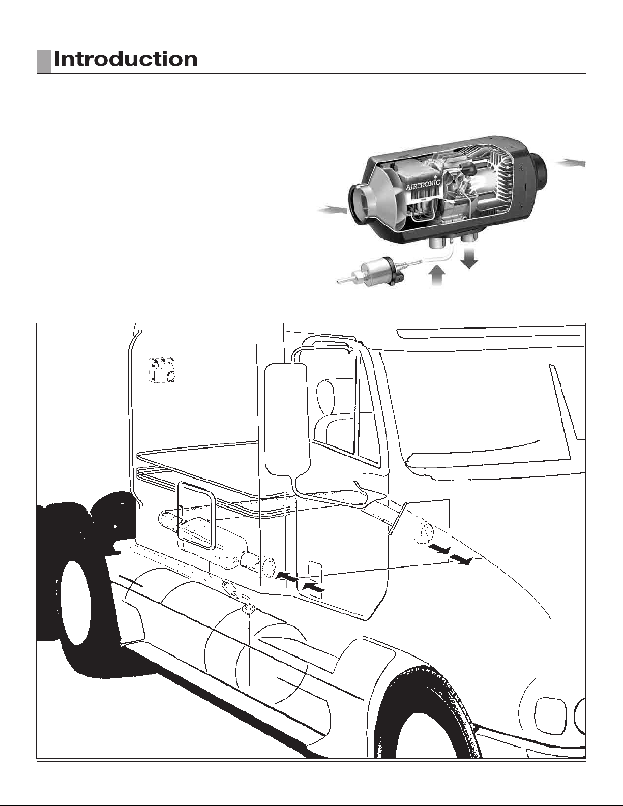
The AIRTRONIC D2 is a compact diesel-red 7,500 BTU/hr air heater, quality
engineered to provide a dependable means of space heating.
This heater is uniquely designed for inside mounting and ease of installation.
The AIRTRONIC D4 is a 13,650 BTU/hr air heater for larger bunks.
These heaters provide hot air to the interior of vehicles for passenger comfort.
Since the heater runs on diesel fuel and are available in 12 or 24 volt versions,
it is able to provide space heat completely independently of the vehicle engine.
Various control options are available to operate the heater. It cycles through
four heat output modes (boost-high-medium-low) in order to maintain the
desired temperature.
In special cases where the heat output required is less then what the “low”
power mode provides the heater switches to “stand-by” mode. Temperature
and overheat sensors, and a specially designed heat exchanger are among
the safety features which make this heater a safe and dependable unit.
AIRTRONIC
BUNK HEATERS
For illustration purposes only
4

2
TECHNICAL DATA
HEATER
Heat Output (±10%) 7,500 BTU/hr Boost (2.2 kW) 13,650 BTU/hr Boost (4.0 kW) 12,950 BTU/hr Boost (3.8 kW)
6,150 BTU/hr High (1.8 kW) 10,200 BTU/hr High (3.0 kW) 10,910 BTU/hr High (3.2 kW)
4,100 BTU/hr Medium (1.2 kW) 6,800 BTU/hr Medium (2.0 kW) 7,160 BTU/hr Medium (2.1 kW)
2,900 BTU/hr Low (0.85 kW) 3,500 BTU/hr Low (1.0 kW) 4,430 BTU/hr Boost (1.3 kW)
Current at 12v (±10%) 8.3 amps - Start 8.3 amps - Start 8.3 amps - Start
2.8 amps - Boost 3.3 amps - Boost 3.3 amps - Boost
1.8 amps - High 2.0 amps - High 2.4 amps - High
1.0 amps - Medium 1.1 amps - Medium 1.3 amps - Medium
0.7 amps - Low 0.6 amps - Low 0.8 amps - Low
0.4 amps - Stand by 0.4 amps - Stand by 0.4 amps - Stand by
Current at 24v (±10%) 4.2 amps - Start 4.2 amps - Start
1.4 amps - Boost 1.7 amps - Boost
0.92 amps - High 1.0 amps - High (No 24V version available)
0.5 amps - Medium 0.5 amps - Medium
0.3 amps - Low 0.3 amps - Low
0.2 amps - Stand by 0.2 amps - Stand by
Fuel Consumption (±10%) U.S. Litre/hr U.S. Litre/hr U.S. Litre/hr
Gal/hr Gal/hr Gal/hr
Boost 0.07 0.28 Boost 0.13 0.51 Boost 0.14 0.54
High 0.06 0.23 High 0.10 0.38 High 0.12 0.46
Medium 0.04 0.15 Medium 0.07 0.25 Medium 0.08 0.29
Low 0.03 0.10 Low 0.03 0.11 Low 0.05 0.18
Air Flow (±10%) 48 cfm Boost 85 cfm Boost 85 cfm Boost
40 cfm High 69 cfm High 74 cfm High
27 cfm Medium 50 cfm Medium 55 cfm Medium
19 cfm Low 30 cfm Low 43 cfm Low
6 cfm Stand by 11 cfm Stand by 11 cfm Stand by
AIRTRONIC
D2
AIRTRONIC
D4
AIRTRONIC
B4
Operating Voltage Range 10.5 - 16 vdc at 12 vdc 10.5 - 16 vdc at 12 vdc 10.5 - 16 vdc at 12 vdc
21 - 32 vdc at 24 vdc 21 - 32 vdc at 24 vdc 21 - 32 vdc at 24 vdc
Overheat Temperature 240°F (115°C) 240°F (116°C) 240°F (116°C)
Shutdown (±10%)
Ambient Operating -40°F to 158°F (-40°C to 70°C) -40°F to 158°F (-40°C to 70°C) -40°F to 122°F (-40°C to 50°C)
Temperature
Weight 5.9 lbs. (2.7 kg) 9.9 lbs. (4.5 kg) 9.9 lbs. (4.5 kg)
PLEASE NOTE!
The heater control unit is equipped with a low voltage cutout to prevent vehicle
battery drain and a high voltage cutout to protect heaterelectrical parts.
PLEASE NOTE!
The terms “Boost” and “Power” are used interchangeably through out this
manual. The terms refer to the highest level of heat output.
5
(12.2 inches)
(4.8 inches)
64.5
89.5
325
122
(4.5 inches)
115
44
min. 17
4 x M6
(14.8 inches)
(5.9 inches)
80
105
325
150
(4.5 inches)
140
44
132.5
min. 17
4 x M6
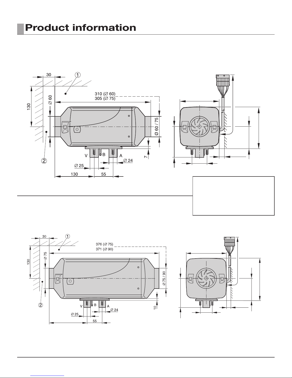
2
HEATER DIMENSIONS
Principal Dimensions
Principal Dimensions
AIRTRONIC
AIRTRONIC
D2
D4
* All measurements in millimeters 25.4 mm = 1”
a Minimum installation distance (clearance)
to open the lid and to dismount the glow
pin and the control unit.
b Minimum installation distance (clearance)
to take in heating air.
6
2
12 11 89
Espar
10
2
1
3
0
4
23
1
F
F
13
32
4
567
21
H
H
14
15 16 17
19
20
18
C
C
22
E
24
E
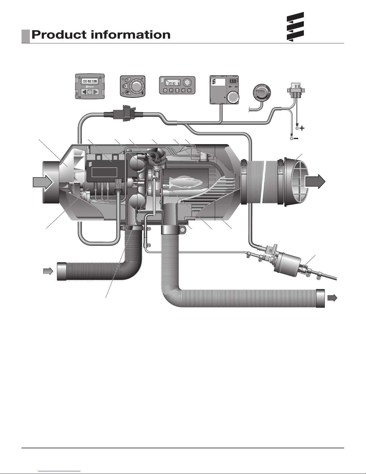
1 Hot Air Blower Wheel
2 ECU
3 Combustion Air Blower Wheel
4 Glow Pin
5 Cover
6 Heat Exchanger
7 Overheat/Flame sensor
8 7 Day Timer with Thermostat (optional)
9 Operating Unit (Thermostat)
10 Operating Unit (Rheostat)
11 Mini Controller
12 Digi Max
13 Blower Motor
14 Fuel Connection
15 Flange Seal
16 Combustion Chamber (Burner)
17 Hot Air Outlet Hood
18 Combustion Air Intake Hose
19 Fuel Metering Pump
20 Fuel Filter built into FMP
21 Hot Air Output Deector
22 Flexible Exhaust Pipe
23 Main Fuse: AIRTRONIC 12 V - 20 A Fuse
AIRTRONIC 24 V - 10 A Fuse
24 Vent Hole
C = Combustion Air
D = Fuel Intake from Tank
E = Exhaust
F = Fresh Air Intake
H = Hot Air Output
7
10
mm
minimum
10
mm
minimum
3
HEATER LOCATION
Depending on the type of vehicle, the best location for mounting the heater will
vary. Typically, air heaters are mounted inside tool or luggage compartments.
However, the heater may be mounted anywhere inside the vehicle provided
you adhere to the following conditions:
• Combustion air intake, exhaust and fuel inlet must be located outside of the
vehicle.
• Heater must be mounted on at horizontal surface providing an air tight
seal between heater and vehicle.
• Do not mount the heater outside the vehicle, unless care is taken to protect
the heater from the weather. When selecting the location, consider the
following:
• Combustion air and exhaust connections.
• Ducting.
• Fuel line connections.
• Electrical connections.
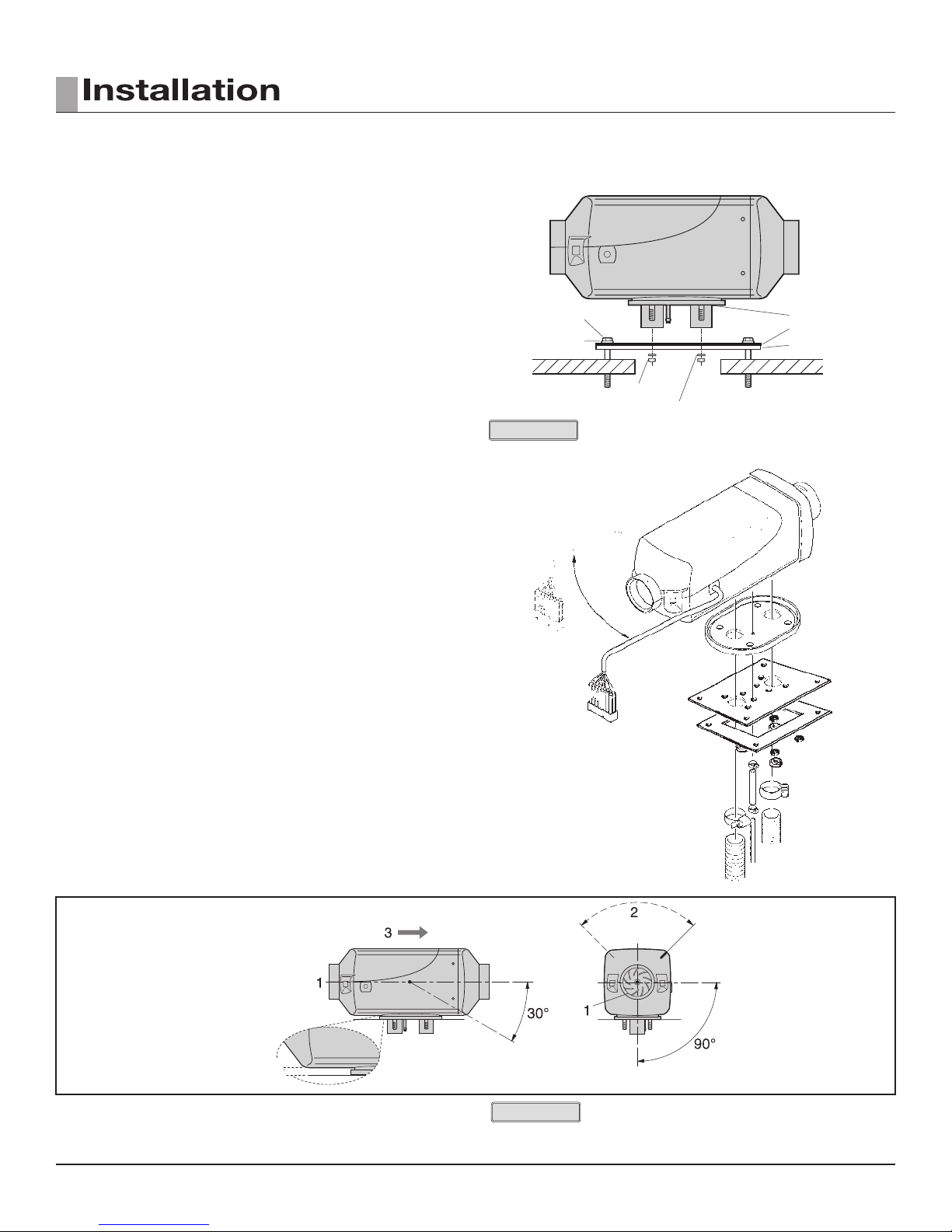
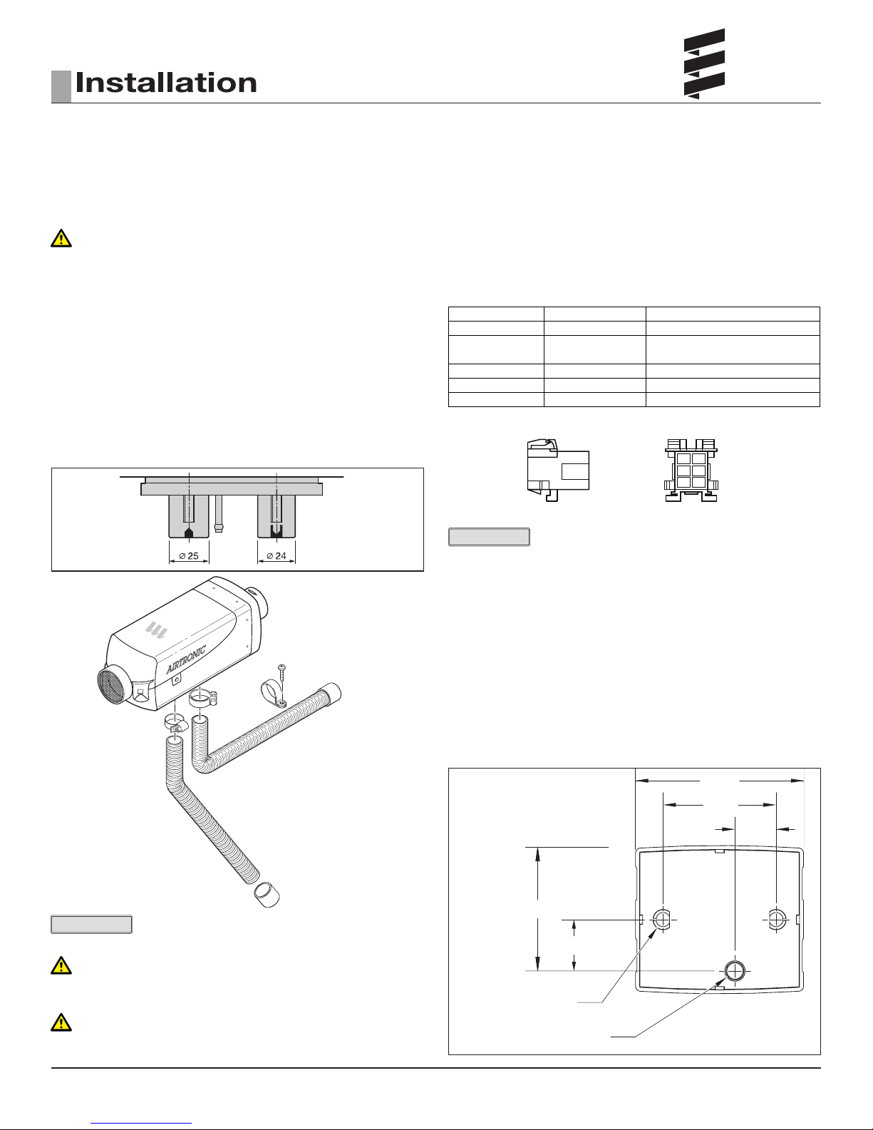
HEATER MOUNTING
A mounting plate and hardware are provided with the truck heater kit.
• Choose heater location.
• Cut a 4-½” hole or a rectangular opening 4”x 5” to accommodate
mounting plate and seal. Secure mounting plate to vehicle with provided
“Tek” screws.
• Mount heater on mounting plate with nuts and spring washers provided.
• If the mounting plate will not be used, the heater ange can be used as a
template to mark where the individual components openings should be
made. (A diagram of the ange is on the fallowing page.)
• For ease of installation make the exhaust, combustion air intake and fuel
connections at the base of the heater before mounting the heater. See the
fallowing pages for instructions and restrictions on the exhaust, combustion
air intake and fuel connections.
HEATER MOUNTING PLATE INSTALLATION
Hex Head Tek Screw
Flat washer
Nut
Spring Washer
Silicon gasket (flange)
Stainless Steel Plate
Plate seal
Cab Floor
PLEASE NOTE!
Tighten screws sufciently to ensure positive seal between mounting plate
and mounting surface.
Do not over tighten.
WIRING HARNESS MOUNTING
For convenient installation and maintenance purposes the wiring harness can
be mounted on the left or right side of the heater housing. To do this the ECU
must be removed from the heater. The bottom of the ECU has is a plastic ap
that holds the wiring in place. Unlatch the plastic ap and position the harness
in the direction that you desire. Before relatching the plastic ap ensure, that
the wiring is laid neatly so that the latch can closed without excessive force.
When mounting the harness to the housing remove the grommet from one
side of the housing and replace on the opposite side.
8
ALLOWABLE MOUNTING ANGLE
PLEASE NOTE!
The following pages refer to a standard installation kit.
Components included with different kits may vary.
3
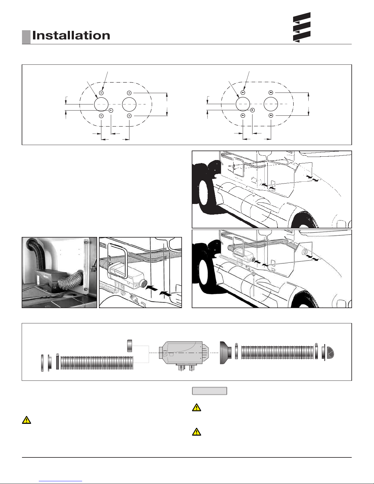
MOUNTING PLATE
INCHES MILLIMETERS
Ø 1.024 (2 HOLES)
0.472
0.709
Ø 0.295 (5 HOLES)
Ø 26.0 (2 HOLES)
12.0
1.732
18.0
2.165
Ø 7.5 (5 HOLES)
44.0
55.0
HEATER WARNINGS
A 60mm exible duct 40 inches long, hot air outlet and clamps are provided
with the heater kit. In routing and installing the ducting the following criteria
must be observed:
• Route ducting with smooth bends. Avoid crushing duct.
• Position hot air outlet so that it cannot be obstructed.
• When not using return ducting. Use a protective air intake grille on air inlet
side of heater to prevent objects from being sucked in.
• Ensure provisions are made for proper air return ventilation.
• Use return air ducting for best heating efciency.
• For exact ducting design specications please refer to Product Catalogue.
DUCTING COMPONENTS
7634
1. Protective Grill 5. Air Outlet - Rotatable
2. Air Outlet Hood 6. Connection Piece
3. Hose Clamp 7. Protective Grill
4. Flex Duct
WARNING
Do not use existing vehicle ducting or outlets.
Ducts and outlets must be capable of withstanding a minimum of 300°F
operating temperatures.
1
PLEASE NOTE!
For exact ducting design specications please refer to
2
3
354
Product Catalogue.
WARNING
Do not over tighten duct clamps. May damage heater and result in a
costly repair.
CAUTION
Do not position outlet so that it will blow hot air directly at operator, at
room thermostat, or return air inlet.
9
3
Ø
1.0”
Ø
1 / 4” (2 HOLES)
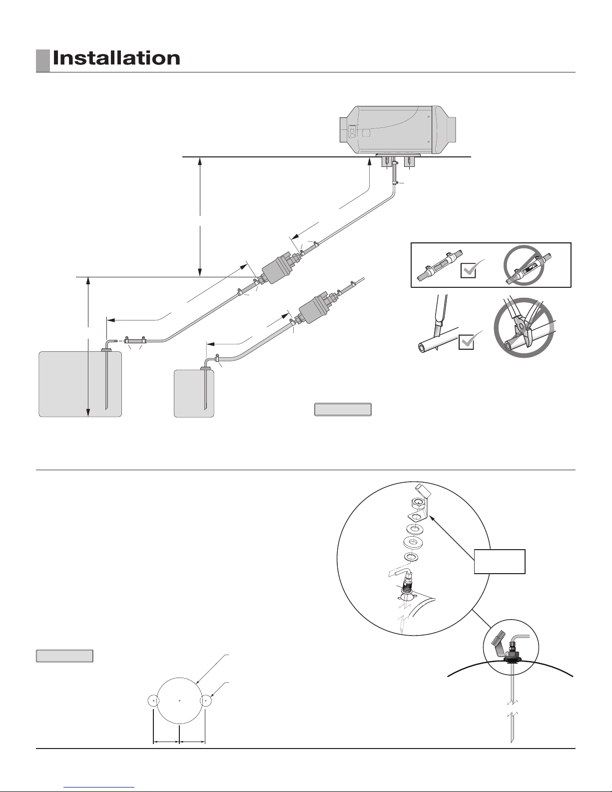
FUEL SYSTEM
The fuel metering pump is the heart of the system and must be
installed properly to ensure successful heater operation.
FUEL SYSTEM OVERVIEW
7
6
Max. 6’6”
2
5
3
Max. 6.6”
4
Max. 2’6”
2
3
Max. 2”
9
3
Fuel
Tank
1
Fuel
Tank
1
Optional
1. Fuel Pick-Up Pipe 4. 2.0mm Black Plastic Fuel Line
2. 5.0mm Rubber Connector 5. Fuel Metering Pump
3. 11mm Clamp 6. 9mm Clamp
FUEL PICK-UP PIPE INSTALLATION (DRILL OPTION)
The fuel metering pump is the heart of the system and must be installed properly to ensure successful heater operation.
Max. 20”
8
6
7
Right Wrong
5
3
Correct
PLEASE NOTE!
Use butt joints and clamps on all connections.
7. 3.5mm Rubber Connector 9. 5mm Rubber Fuel Line
8. 1.5mm or 2.0mm White
Plastic Fuel Line
Bubble
Wrong
• Choose a protected mounting location close to the fuel pump and heater.
A spare fuel sender gauge plate provides an ideal mounting location.
• Drill the mounting holes as shown.
• Tighten Ferrule nut to pick-up pipe at desired height.
• Cut the fuel pick-up pipe to length.
• Mount the fuel pick-up pipe as shown.
• Lower the fuel pick-up pipe (with reinforcing washer) into the tank using
the slot created by the two 1/4” holes.
• Lift the assembly into position through the 1” hole.
• Assemble the rubber washer, fuel metering pump bracket, metal cup
washer and nut.
PLEASE NOTE!
Drill the two 1/4” holes rst.
10
FMP Bracket
Optional
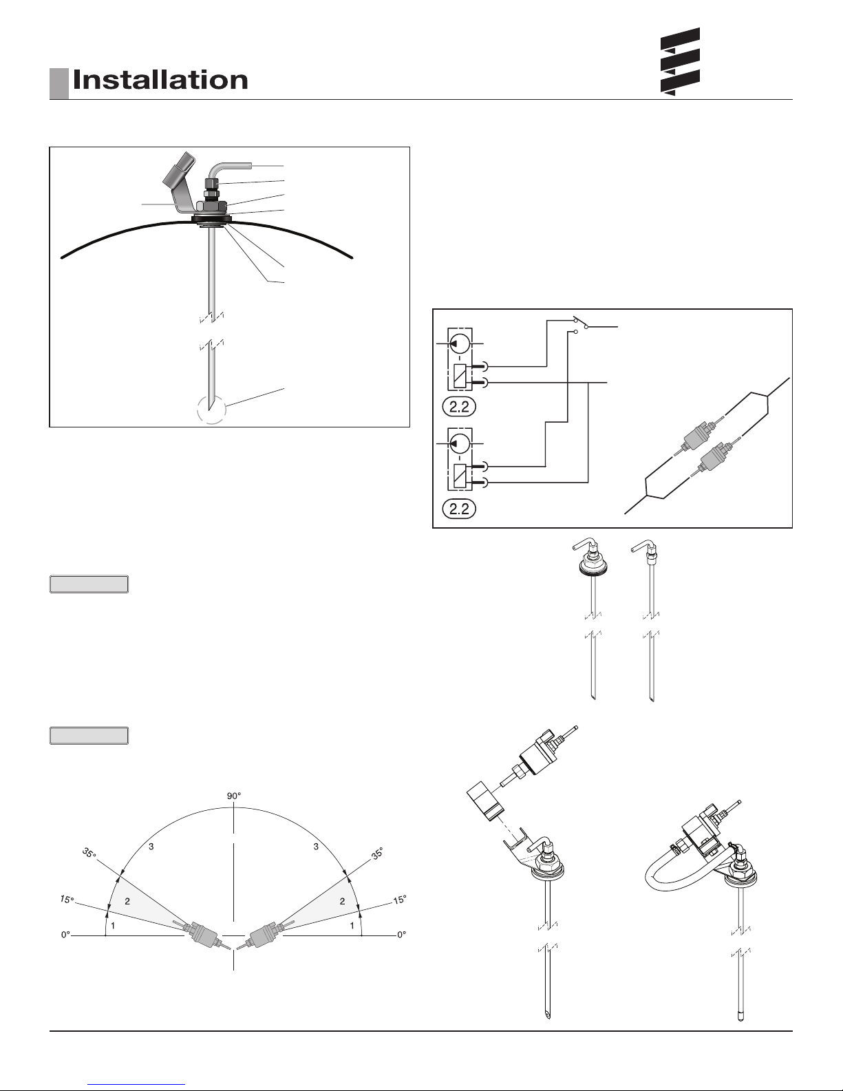
3
FMP
Fuel Pick-up Pipe
Ferrule Nut (Tighten before installing)
FMP bracket
Fuel Tank
Nut
Sheet Metal Washer
(raised center to top)
Reinforcing Washer
Holding Tabs
Allow 4" from Fuel
Pick-up to tank bottom.
Allow only 1" for flat
bottom tanks.
CUSTOM PICK-UP PIPE WITH 1/4” NTP FITTING - OPTION
Standard pick-up pipe can be installed as a drill type installation
or 1/4 NPT type installation.
• Remove an existing NPT plug from the top of the fuel tank.
• Cut the fuel pick-up pipe to length.
• Secure the fuel pick-up pipe into position using the combined NPT
compression tting.
FUEL LINE
• Route fuel lines from the fuel pick-up pipe to the fuel metering pump then
to the heater.
• Use fuel lines provided.
• Other sizes or types of fuel lines may inhibit proper fuel ow.
• Make proper butt joints using clamps and connector pieces as shown on
previous page.
• Use a sharp utility knife to cut plastic fuel lines to avoid burrs and pinching
fuel line shut.
To Pin 5 (of 16 pin connector)
Green / Red
Brown
Green / Red
Brown
To Pin 10 (of 16 pin connector)
Normal FMP
High Altitude FMP
PLEASE NOTE!
FMP bracket is not compatible with NPT pick up option.
Refer to product catalogue for other pick-up pipe options.
FUEL METERING PUMP
• Choose a protected mounting location close to the fuel pick- up pipe and
heater if not using standard assembly as shown on right.
• Using the bracket and rubber mount provided, install fuel pump as shown.
PLEASE NOTE!
Proper mounting angle of the fuel pump is necessary to allow any air or vapor
in the fuel lines to pass through the pump rather than cause a blockage.
Permissible
preferable
preferable
not permissiblenot permissible
1 Installation position between 0° and 15° is not allowed.
2 Preferred installation position in range 15° to 35°.
3 Installation position in range 35° to 90° is allowed.
Typical standard
assembly, if not
using this format
please adhere to
specications on
pg.10
11
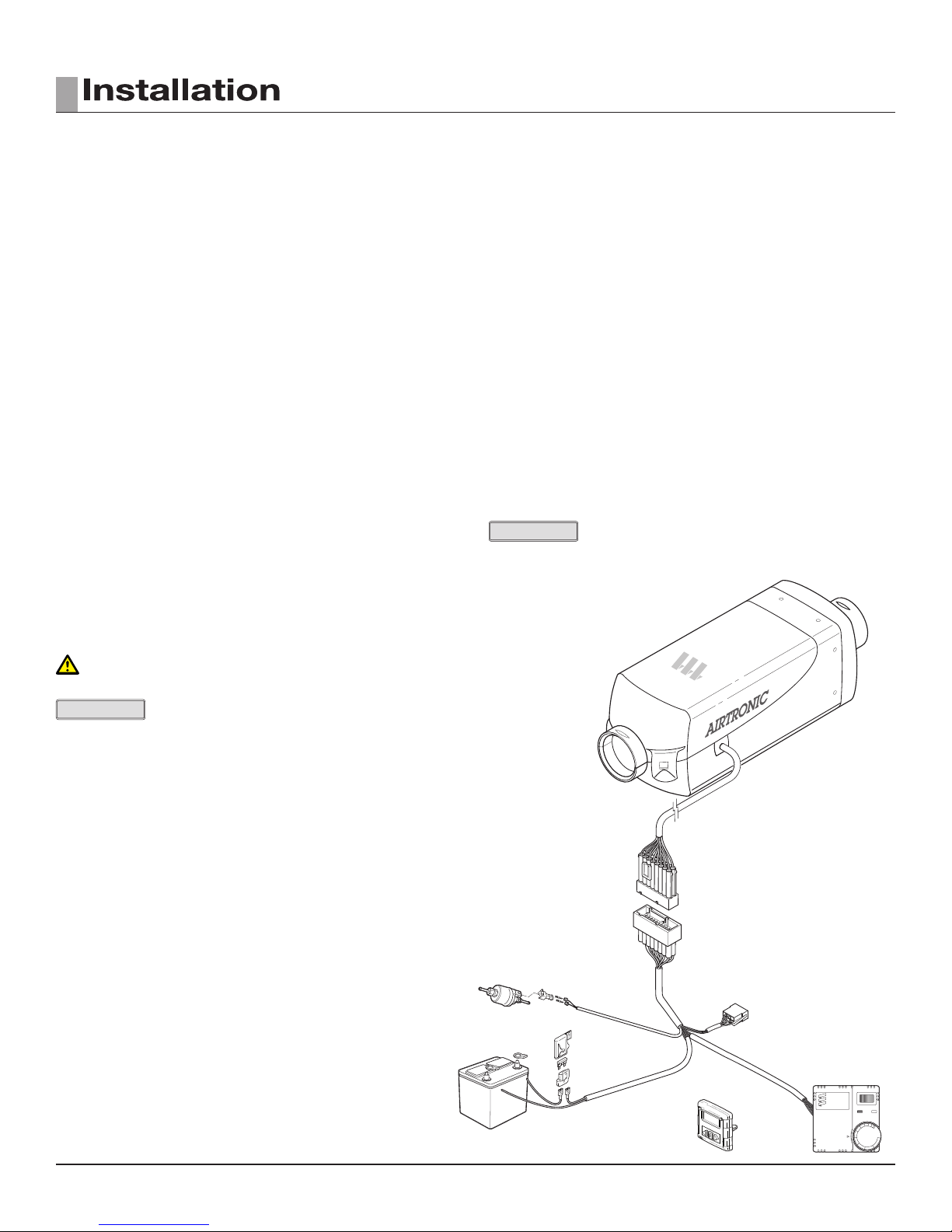
Espar
Main Harness
Fuel Metering Pump Harness
Connector for Diagnostics
Switch Harness
Thermostat
Power Harness
Fuel and holder
3
ELECTRICAL CONNECTIONS
Main Harness ..............................................................................................
Power Harness .........................................................................
Switch Harness ........................................................................
Fuel Metering Pump Harness ....................................................
Diagnostic Harness ..................................................................
16 pin connector with 10 terminated wires at 8 terminals (green/red, blue/
white (2), red, grey/red, grey, brown, brown/white and yellow (2)). Connect to
the heater’s 16 pin connector. Main harness branches off to sub harness’s
described below.
2 core harness (red and brown). Route power harness to batteries, cut to
length and terminate. Install 20 amp fuse last (10 amp on 24V). Connect red
wire to fuse holder near battery.
Connect fuse link wire directly to battery positive post using ring terminal.
Connect brown wire directly to battery negative post using ring terminal.
7 core harness (red, brown/white, yellow, grey, brown, grey/red and blue/
white). Route this harness to the control option mounted in the cab. Do
not cut this harness, wires have been soldered at ends for convenience of
terminating to terminals of the control option.
Coil up excess harness and secure in safe location.
Connect to control option (refer to switch connection section).
2 core harness (green/red and brown).
Route this harness from heater to fuel metering pump. Cut to length and
connect to fuel metering pump using single terminals and connector provided
with kit.
PLEASE NOTE!
Polarity does not matter for FMP connection.
8 pin connector (red, brown, yellow, blue/white). For diagnostic purposes only.
CAUTION: Install power 20 amp fuse only after all electrical connections
are complete. (10 amp fuse on 24V.)
PLEASE NOTE!
All exposed electrical connections should be coated with protective grease,
(petroleum gel, Vaseline, etc.).
12
3
OPERATION AND FUNCTION
EXHAUST AND COMBUSTION AIR INTAKE CONNECTIONS
A 24mm exible stainless steel exhaust pipe (40” long) and a 25mm exible
plastic tube (40” long) for combustion air intake are included with the heater
kit. Exhaust clamps and holders are also provided.
CAUTION!
Route exhaust and combustion air intakes so they cannot be plugged by dirt,
water or snow. Ensure the outlets do not face into the vehicle slip stream.
Keep exhaust and combustion air intake a minimum of 12” apart.
Drill 1/8” holes in exhaust pipe if necessary to allow water drainage.
Combustion air intake and exhaust lengths can be shortened to a minimum of 8”.
• Attach the exhaust pipe to the exhaust outlet of the heat exchanger.
• Route exhaust pipe to an open area to the rear or side of the vehicle so
that fumes cannot build up and enter the cab or the combustion air inlet to
the heater.
• Install protective cap.
• Attach the combustion air intake tube to the combustion air inlet of the
heater.
• Once secure to the heater inlet, the intake pipe must be routed to the
underside of the vehicle where it will pick up clean, fresh, moisture free air.
OPERATING SWITCHES
The heater can be controlled using a Digi-Max D1000, Thermostat or Rheostat
type switch. It can also be controlled by a 7 day timer with thermostat. See
schematic pg. 19.
WIRING
PIN CONNECTIONS
CONTROLLER HARNESS
Red Connect to pin 1 Red,+ Power
Yellow Connect to pin 2 Yellow, ON/OFF
Brown/White
Brown/White Connect to pin 3
Ground Reference
Grey/Red Connect to pin 4 Grey/Red Temperature setpoint
Grey* Connect to pin 5 Grey Temperature sensor
Blue/White Connect to pin 6 Blue/White Diagnostic
* The grey cable is an optional connection for temperature sensor.
12
34
56
Side View Cable Entry View
(Rear View)
PLEASE NOTE!
Insulate any cable ends not used.
The connectors and socket housing are shown from the cable entry side.
End Cap
End Cap
Exhaust ( min 8” - max 6.5’ )
Exhaust ( min.8” - max. 6.5’ )
Combustion Air Intake
( min 8” - max 6.5’ )
PLEASE NOTE!
Bends in both the intake and exhaust pipes should be kept to
Combustion Air Intake
( min.8” - max. 6.5’ )
End Cap
End Cap
a minimal. For every 90° bend it is recommended to shorten pipe by 16” (40cm).
WARINING!
The exhaust is hot, keep a minimum of 2” clearance from any heat
sensitive material.
WARINING!
Route exhaust so that the exhaust fumes cannot enter the passenger
compartment.
THERMOSTAT
• Select a mounting location which will be representative of the average
temperature of the area being heated. Avoid mounting near heater outlets,
windows, doors, electrical appliances or in areas receiving direct sunlight.
• Route the switch harness from the heater to the thermostat mounting
location.
• Mount the thermostat as shown using proper mounting hardware and the
slots provided on the thermostat base. Pull the switch harness through the
thermostat base access hole.
• Connect the six core switch harness to the thermostat as shown.
DRILLING TEMPLATE
( 65.5 mm )
(2.58”)
( 44 mm )
(1.73”)
( 16 mm )
(0.63”)
57.66 mm
(2.27”)
20 mm
(0.79”)
2 x Ø 7.74 (19/64”) FIXING S FOR
CONTROLLER LUGS
Ø 9.5 (3/8”) FIXING
FOR CABLE ENTRY HOLE
SECTION A-A
SCALE 1 : 1
13
 Loading...