

Eberspächer Airtronic S2 D2L, Airtronic M2 D4L, Airtronic M2 D4R, Airtronic M2 B4L Technical Description
ENVehicle Heaters|Technical Documentation
TECHNICAL DESCRIPTION
AIRTRONIC S2 COMMERCIAL
AIRTRONIC M2 COMMERCIAL / AIRTRONIC M2 RECREATIONAL
Air heaters for diesel fuel Order No.
Airtronic S2, D2L, 12 V 25.2721.05.0000
Airtronic S2, D2L, 24V 25.2726.05.0000
Airtronic M2, D4L, 12 V 25.2720.05.0000
Airtronic M2, D4L, 24V 25.2729.05.0000
Airtronic M2, D4R, 12 V 25.2746.05.0000
Air heaters for petrol Order No.
Airtronic M2, B4L, 12 V 20.1987.05.0000
The technical description and installation instructions are
valid for the following engine-independent air heaters:
Order No. incl. EasyStart Pro
25.2753.05.0000
25.2754.05.0000
25.2755.05.0000
25.2756.05.0000
25.2757.05.0000
Order No. incl. EasyStart Pro
20.2032.05.0000
www.butlertechnik.com
Visit us www.butlertechnik.com for more technical information and downloads
Chapter Chapter title Page
Chapter contents
1 Introduction
1.1 Concept of this document 4
1.2 General information 4
1.3 Reference documents 4
1.4 Special text formats and presentations 4
1.4.1 Lists 4
1.4.2 Cross references 4
1.5 Picture symbols 4
1.6 Intended use 5
1.6.1 Range of application of the heater 5
1.6.2 Intended use of the heater 5
1.7 Non-intended use 5
1.8 Disclaimer 5
1.9 Target groups of this document 5
1.10 Duty to instruct of the target groups 5
1.11 Statutory regulations 6
1.12 Additional regulations 7
1.13 Hazard information and safety instructions for installation and operation 8
1.14 Accident prevention 9
2 Product Information
2.1 Scope of supply, heater 9
2.2 Scope of supply, heater incl. EasyStart Pro 9
2.3 Scope of supply – heater, installation kit and additional parts 10
2.4 Technical data 11
2.4.1 Airtronic S2 D2L 11
2.4.2 Airtronic M2 D4L 12
2.4.3 Airtronic M2 D4R 13
2.4.4 Airtronic M2 B4L 14
2.5 Main dimensions, Airtronic S2 15
2.6 Main dimensions, Airtronic M2 15
3 Installation
3.1 Nameplate 16
3.2 Installation and mounting position 16
3.3 Installation in a camper van 16
3.4 Installation in a car or people carrier 16
3.5 Installation in an excavator cab (only diesel heaters) 17
3.6 Installation in a truck (only diesel heaters) 17
3.7 Permissible installation positions 17
3.8 Normal position horizontal (exhaust connection downwards) with tolerable swivel range 17
3.9 Cable harness connection, optionally right or left-hand 18
Technical Description | Airtronic S2 / M2
2 25.2720.90.0001.0A EN | 02.2018
www.butlertechnik.com
Visit us www.butlertechnik.com for more technical information and downloads

3.10 Installation and fixing 18
3.11 Hot air system 19
3.12 Mounting the air outlets and pipe connection sockets 20
3.13 Installing the air blocking element 20
3.14 Exhaust system 21
3.15 Combustion air system 22
3.15.1 Mounting the combustion air system 22
3.16 Fuel supply 22
3.17 Fuel quality for petrol heaters 25
3.18 Fuel quality for diesel heaters 25
3.19 Heating oil operation with additional tank 25
4 Operation and Function
4.1 Instructions for operation 25
4.2 Notes on ADR mode 26
4.2.1 Forced shutdown in ADR mode 26
4.3 Initial startup 26
4.4 Functional description 26
4.5 Control and safety devices 27
4.6 Emergency stop – EMERGENCY OFF 27
5 Electrics
5.1 Heater wiring 28
5.2 Parts list for the AirtronicS2 and AirtronicM2 circuit diagrams 28
5.3 Circuit diagrams for Airtronic 29
5.3.1 Heater 29
5.3.2 Cable harness 30
5.3.3 Cable harness with ADR (24V only) 31
5.4 Circuit diagrams for control units 32
5.4.1 EasyStart Pro 32
5.4.2 EasyStart Web (12V only) 33
5.4.3 EasyStart Remote+ (12V only) 34
6 Fault / Maintenance / Service
6.1 If any faults occur, please check the following items 35
6.2 Troubleshooting 35
6.3 Maintenance instructions 35
6.4 Service 35
7 Environment
7.1 Certification 35
7.2 Disposal 35
7.3 EU Declaration of Conformity 35
8 List
8.1 List of abbreviations 36
Technical Description | Airtronic S2 / M2
25.2720.90.0001.0A EN | 02.2018 3
www.butlertechnik.com
Visit us www.butlertechnik.com for more technical information and downloads
1 Introduction
1.1 Concept of this document
This document supports the service company or installation company
installing the heater and provides the user with all important information about the heater. The document is divided into the following
chapters to make it easier to find information quickly:
1 Introduction
Important, introductory information about use and the structure of
this document
2 Product information
Information about the scope of supply, technical data and
dimensions.
3 Installation
Information and notes concerning installation of the product
4 Operation and Function
Information on operation and function of the product
5 Electrics
Information on the electronics and electronic components.
6 Troubleshooting / Maintenance / Service
Information on possible faults, maintenance and support
7 Environment
Information about certification, disposal of the heater and the EC
Declaration of Conformity
8 List
Information about abbreviations used in the document.
1.2 General information
This document is used to install the heaters listed on the title page
and applies to the exclusion of all liability claims. The installation
work may only be carried out by appropriately trained personnel of an
Eberspächer service partner.
Depending on the version or revision status of the heater, differences may occur compared to this documentation. Please check this
before carrying out the installation and take into account possible
differences.
1.3 Reference documents
Spare parts list
Contains the information necessary for ordering spare parts for the
heater.
Repair instructions
Contains the necessary information for troubleshooting and for repair
of the heater.
Installation recommendation
Describes vehicle-specific installation situations.
Installation Instructions Plus
Supplementary information on heaters and control units.
1.4 Special text formats and presentations
Special text formats and picture symbols are used in these instruc-
tions to emphasise different situations and subjects. Refer to the
following examples for their meanings and appropriate action.
1.4.1 Lists
This dot () indicates a list or action step, introduced by a heading.
– If an indented dash (–) follows a “dot”, this list/action step is a
sub-section/secondary step of the black dot.
1.4.2 Cross references
Underlined blue textdenotes a cross-reference, which can be clicked
in the PDF format.
The part of the document named in the text is then
displayed.
1.5 Picture symbols
Regulation!
This information indicates a statutory regulation. Any violation of
these regulations results in expiry of the type-approval for the
heater and exclusion of any guarantee and liability claims against
Eberspächer Climate Control Systems GmbH & Co. KG.
Danger!
“Danger” indicates a situation that can directly result in death or
serious injuries if not avoided.
Æ This arrow indicates the appropriate measures to avert the immi-
nent danger.
Warning!
“Warning” indicates a situation that can potentially result in death or
serious injuries if not avoided.
Æ This arrow indicates the appropriate measures to avert the
potential danger.
Caution!
“Caution” indicates a situation that can potentially result in minor or
slight injuries if not avoided.
Æ This arrow indicates the appropriate measures to avert the
potential danger.
Technical Description | Airtronic S2 / M2
4 25.2720.90.0001.0A EN | 02.2018
www.butlertechnik.com
Visit us www.butlertechnik.com for more technical information and downloads
Note
This note contains recommendations for use and useful tips for the
operation, installation and repair of the product.
1.6 Intended use
1.6.1 Range of application of the heater
The air heater operating independently of an engine is intended for
installation in the following vehicles:
All types of vehicles (max. 8 seats + driver's seat) and their trailers
Construction machinery
Agricultural machinery
Boats, ships and yachts (only diesel heaters)
Camper vans
1.6.2 Intended use of the heater
Pre-heating, de-misting windows
Heating and keeping the following warm:
– Driver and working cabs, ship's cabins
– Freight compartments
– Passenger and crew compartments
– Camper vans
Note
Only use and operate the heater within the scope of the intended use
stated by the manufacturer and in compliance with the documenta-
tion enclosed with each heater.
1.7 Non-intended use
On account of its functional purpose, the heater is not approved for
the following applications:
Long-term continuous operation, e.g. for heating:
– Residential rooms
– Garages
– Work huts, weekend homes and hunting lodges
– Houseboats, etc.
Heating or drying of:
– Living creatures (people or animals) by blowing hot air directly
at them
– Objects
– Blowing hot air into containers
Warning!
Risk of undercooling!
The heater does not replace a temperature-monitored and
controlled heating system, which ensures that a constant temperature is maintained and thus ensures survival in adverse weather
conditions. It is not suitable for the continuous heating of vehicle
interiors at low outdoor temperatures.
Use, operation and deployment of the product outside the intended
use stated by the manufacturer can cause considerable injuries to
people and/or damage to machinery and property.
Æ Only use the project for the stipulated purpose and in the
approved area of use.
1.8 Disclaimer
The manufacturer is not liable for damage caused by improper use
or incorrect operation. Failure to comply with the safety instructions
makes the guarantee null and void and this leads to the exclusion of
any liability of Eberspächer Climate Control Systems GmbH & Co. KG.
1.9 Target groups of this document
This document is aimed at the following target groups:
Service company
The “service company” target group includes all service companies
trained by Eberspächer that purchase heaters and air-conditioners
and their control units, accessories and spare parts from Eberspächer
or the trade and install, repair or service these on behalf of an end
user.
Installation company
The “installation company” target group includes all companies
trained by Eberspächer that purchase heaters and air-conditioners
and their control units, accessories and spare parts from Eberspächer
and install, repair or service these on behalf of another company
(usually the automotive / body manufacturer).
End user
The “end user” target group includes all natural persons who operate
a heater or air conditioner with the help of a control unit, regardless
of whether they act as a consumer or as part of their job.
1.10 Duty to instruct of the target groups
Each named target group must fulfil their duty to instruct in full. The
duty to instruct relates to the passing on of technical documents.
Technical documents are all documents published by Eberspächer for
the installation, operation, use, maintenance or repair of heaters and
air conditioners and their control units, accessories and spare parts.
Technical Description | Airtronic S2 / M2
25.2720.90.0001.0A EN | 02.2018 5
www.butlertechnik.com
Visit us www.butlertechnik.com for more technical information and downloads

Note
If not explicitly defined in the following, the technical documents
can be passed on printed out as hard copies, on a data carrier or
by internet download.
Current technical documents can be downloaded from the
Eberspächer website.
Responsibility of the installation company
The installation company must pass on the following technical documents to the company that employs them, and it in turn is obliged to
pass on the documents to the end user:
Technical description
Operating instructions
Responsibility of the service company
The service company must pass on the following technical documents to the end user, even if they employ a subcontractor:
Technical description
Operating instructions
Note
The named target groups must ensure that the operating instructions
produced by the manufacturer for the product are made available to
the end user in printed form and in their own national language. If
necessary this can be a short form of the detailed operating instruc-
tions, which are additionally enclosed with the product on a data
carrier or are available to download from the internet.
1.11 Statutory regulations
The Federal Motor Transport Authority has issued an approval for a
component according to ECE-R122 and ECE-R10 for the heater for
installation in motor vehicles, with the following official type-approval
markings noted on the heater's nameplate.
Heater type: ECE type approval mark:
Airtronic S 2
122 R – 000523
10 R – 058206
AirtronicM 2
122 R – 000477
10 R – 057672
Regulation!
Excerpt from ECE regulation No. 122 of the European Parliament
and the Council
General regulations
Operating state display
A clearly visible operating display in the user's field of vision must
indicate when the heater is switched on and off.
Regulations concerning installation in the vehicle
Scope
Subject to differing stipulations in the following section, combus-
tion heaters must be installed according to the regulations 5.3 of
ECE-R122.
It is assumed that Class
O
vehicles with heaters for liquid fuel
conform to the regulations 5.3 of ECE-R122.
Arrangement of the heater
Parts of the structure and other components near the heater must
be protected from excessive heat exposure and possible fuel or oil
contamination.
The combustion heater shall not constitute a risk of fire, even in
the case of overheating. This requirement shall be deemed to be
met if the installation ensures an adequate distance to all parts
and suitable ventilation, by the use of fire resistant materials or by
the use of heat shields.
The heater must not be installed in the passenger compartment
of class M
2
and M3 vehicles. However, a heater in a hermetically
sealed enclosure which also complies with the aforementioned
conditions may be used.
The nameplate, or a duplicate, must be positioned so that it can be
easily read when the heater is installed in the vehicle.
Every reasonable precaution should be taken in positioning the
heater to minimize the risk of injury and damage to personal
property.
Fuel supply
The fuel filler neck must not be located in the passenger compart-
ment and must be sealed with a properly closing cover to prevent
any fuel leaks.
In heaters for liquid fuel where the heater fuel supply is separate
from the vehicle fuel supply, the type of fuel and filler neck must
be clearly marked.
A warning sign is to be attached to the filler neck informing that
the heater must be switched off before refuelling.
Exhaust system
The exhaust outlet must be arranged so as to prevent any penetration of exhaust fumes into the vehicle interior through the ventilation
system, warm air intakes or open windows.
Combustion air intake
The air for the heater's combustion chamber may not be drawn in
from the vehicle's passenger compartment.
The air intake must be arranged or protected in such a way that it
cannot be blocked by other objects.
Technical Description | Airtronic S2 / M2
6 25.2720.90.0001.0A EN | 02.2018
www.butlertechnik.com
Visit us www.butlertechnik.com for more technical information and downloads
Hot air intake
The hot air supply must consist of fresh air or circulated air and
must be drawn in from a clean area, which cannot be contaminated by exhaust fumes from the engine, the combustion heater or
any other source in the vehicle.
The intake pipe must be protected by a grille or other suitable
means.
Hot air outlet
The hot air pipes within the vehicle must be arranged or protected
in such a way that there is no risk of injury or damage if they are
touched.
If there is a risk of the driver and/or passengers touching the
heater or hot air system parts during normal vehicle operation,
protection against contact must be fitted in these places.
The air outlet must be arranged or protected in such a way that it
cannot be blocked by any objects.
Automatic control of the heating system
If the engine fails, the heating system must be switched off automatically and the fuel supply stopped within 5 seconds. The heater may
remain in operation if a manual device has already been activated.
Note
Compliance with the statutory regulations, the additional regula-
tions and the safety instructions is prerequisite for guarantee and
liability claims. Failure to comply with the statutory regulations
and safety instructions and incorrect repairs, even if original spare
parts are used, make the guarantee null and void and this results
in the exclusion of any liability whatsoever of Eberspächer Climate
Control Systems GmbH & Co. KG.
Subsequent installation of the heater must comply with these
installation instructions.
The statutory regulations are binding and must also be observed in
countries which do not have any special regulations.
When installing the heater in vehicles not subject to the German
Road Traffic Licensing Regulations (StVZO), for example ships,
observe the respective specially valid regulations and installation
instructions.
When installing the heater in special vehicles, comply with the
regulations applying to such vehicles.
Further installation requirements are printed in the relevant sec-
tions of these installation instructions.
1.12 Additional regulations
Regulation!
Additional regulations for certain vehicles named in Directive
94 / 55 / EC of the ADR Agreement
Scope
This annex applies to vehicles to which the special provisions of
Directive 94 / 55 / EC of the ADR Agreement for combustion heaters
and their installation apply.
Definition of terms
The vehicle designations “EX / II”, “EX / III”, “AT”, “FL” and “OX”
according to Chapter 9.1 of the ADR Agreement Directive are used for
the purposes of this annex.
Technical specifications
General regulations (vehicles EX / II, EX / III, AT, FL and OX)
Avoid heating and ignition
Combustion heaters and their exhaust pipes must be designed,
arranged, protected or covered to avoid any unacceptable risk of
heating or ignition of the load. This requirement is met if the fuel
tank and the exhaust system of the heater comply with the requirements described in the “fuel tank” and “exhaust system and exhaust
pipe layout” sections. Compliance with these requirements must be
checked on the complete vehicle.
Fuel tank
Fuel tanks for supply of the heater must conform to the following
regulations:
In the event of a leakage, the fuel must be drained to the floor
without coming into contact with any hot vehicle parts or the
vehicle's load;
Fuel tanks which contain petrol must be equipped with a flame
arrester or hermetically sealed cap at the filler neck.
Exhaust system and exhaust pipe layout
The exhaust system and the exhaust pipes must be laid or protected
so that dangerous heating or ignition of the vehicle's load cannot
occur. Parts of the exhaust system located directly under the fuel
tank (diesel fuel) must be positioned at a distance of at least 100 mm
from the tank or be protected by a heat shield.
Switch on combustion heater
The combustion heater may only be switched on manually. Automatic
switching on via a programmable switch is not allowed.
EX / II and EX / III vehicles
Combustion heaters for gaseous fuel are not allowed.
Technical Description | Airtronic S2 / M2
25.2720.90.0001.0A EN | 02.2018 7
www.butlertechnik.com
Visit us www.butlertechnik.com for more technical information and downloads
FL vehicles
Combustion heaters must at lease be able to be taken out of service
by the procedures named in the following:
Switching off manually in the driver's cab
Shutdown of the vehicle's engine; in this case the heater may be
switched back on manually by the vehicle driver;
Starting up an installed fuel pump in the vehicle for transported
dangerous goods.
After running of the combustion heater
After running of the switched off combustion heater is permitted. In
the cases named in the “FL vehicles” section under letters b) and c),
the supply of combustion air must be interrupted by suitable means
following an after-running period of 40 seconds maximum. Only combustion heaters whose heat exchangers are verifiably not damaged
by the reduced after-running time of 40 seconds beyond their usual
operating period may be used.
Notes
Compliance with the statutory regulations, the additional regula-
tions and the safety instructions is prerequisite for guarantee and
liability claims.
– Failure to comply with the statutory regulations and safety
instructions and incorrect repairs, even if original spare parts
are used, make the guarantee null and void and exclude any
liability whatsoever of Eberspächer Climate Control Systems
GmbH & Co. KG.
Subsequent installation of this heater must comply with these
installation instructions.
The statutory regulations are binding and must also be observed in
countries which do not have any special regulations.
When installing the heater in vehicles not subject to the German
Road Traffic Licensing Regulations (StVZO), for example ships, the
respective specially valid regulations and installation instructions
must be observed.
Installation of the heater in special vehicles must comply with the
regulations applying to such vehicles.
Further installation requirements are printed in the relevant sec-
tions of these installation instructions.
1.13 Hazard information and safety instructions for
installation and operation
Danger!
Risk of injury, fire and poisoning!
Only start up the heater if the maintenance flap is closed and the
outlet hood is mounted in position.
Do not open the maintenance flap during operation.
Disconnect the vehicle battery before starting any kind of work.
Before working on the heater, switch the heater off and let all hot
parts cool down.
Do not start up the heater in enclosed spaces, e.g. garage or
multi-storey car park.
Always adjust hot air outlets so that they cannot blow hot air
directly at living creatures (people, animals) or objects sensitive to
temperature (loose and / or fastened).
Caution!
Safety instructions for installation and operation!
Mark the year of initial commissioning on the nameplate.
Replace the heat exchanger of air heaters, a component subject to
high thermal loads, 10 years after the initial commissioning of the
heater. In addition, enter the installation date on the “original spare
part” plate enclosed with the heat exchanger. Then affix the plate
next to the nameplate on the heater.
Have the heater installed only by a service partner authorised by
the manufacturer according to the instructions in this manual,
possibly according to special installation recommendations; the
same applies to any repairs to be carried out in the case of repairs
or guarantee claims.
Only use the control units approved by the manufacturer to operate
the heater. Use of other control units can cause malfunctions.
Repairs by unauthorised third parties and/ or not using original
spare parts are dangerous and therefore not allowed. They result
in expiry of the type-approval of the heater; consequently, when
installed in motor vehicles they can cause expiry of the vehicle
operating licence.
The following measures are not allowed:
– Changes to heating-relevant components.
– Use of third party parts not approved by the manufacturer.
– Deviations from the statutory, safety and/ or functionally rele-
vant requirements stated in this document regarding installation
and/or operation. This applies in particular to the electrical
wiring, fuel supply, combustion air system and exhaust system.
Only use original accessories and original spare parts for installa-
tion and repairs.
When carrying out electric welding on the vehicle, disconnect the
positive cable at the battery and attach it to ground to protect the
control box.
It is not permitted to operate the heater where there are readily
flammable materials (e.g. dry grass, leaves, paper, etc.) in the area
of the exhaust system or where ignitable fumes and dust can form,
e.g. near a
– fuel depot
– coal depot
– wood depot
– grain storage and similar.
Switch off the heater before refuelling.
If the heater is installed in a safety housing or similar, the heater's
installation box must not be used as storage space and must be
kept clear. In particular, do not store or transport fuel canisters, oil
cans, spray cans, gas cartridges, fire extinguishers, cleaning rags,
items of clothing, paper etc. on or next to the heater.
Replace defective fuses only with fuses with the specified fuse
rating.
Technical Description | Airtronic S2 / M2
8 25.2720.90.0001.0A EN | 02.2018
www.butlertechnik.com
Visit us www.butlertechnik.com for more technical information and downloads

If fuel escapes from the heater's fuel system (leak), arrange
for immediate repair of the damage by an Eberspächer service
partner.
Do not cancel the after-running of the heater prematurely, e.g. by
pressing the battery isolating switch, except for an emergency
stop.
Note
All deviations from the safety requirements for installation and
operation are to be agreed with the manufacturer in writing before
they are implemented.
Following installation, attach the “Switch off heater before refuel-
ling!" sticker near the tank filler neck.
1.14 Accident prevention
Observe the general accident prevention regulations and the relevant
workshop and operating safety instructions.
2 Product Information
2.1 Scope of supply, heater
Heater Order No.
Airtronic S2, D2L, 12V 25.2721.05.0000
Airtronic S2, D2L, 24V 25.2726.05.0000
Airtronic M2, D4L, 12V 25.2720.05.0000
Airtronic M2, D4L, 24V 25.2729.05.0000
Airtronic M2, D4R, 12V 25.2746.05.0000
Airtronic M2, B4L, 12V 20.1987.05.0000
The scope of supply includes
Figure No. Designation
1 Heater
2 Metering pump
2.2 Scope of supply, heater incl. EasyStart Pro
Heater Order No.
Airtronic S2, D2L, 12V 25.2753.05.0000
Airtronic S2, D2L, 24V 25.2754.05.0000
Airtronic M2, D4L, 12V 25.2755.05.0000
Airtronic M2, D4L, 24V 25.2756.05.0000
Airtronic M2, D4R, 12V 25.2757.05.0000
Airtronic M2, B4L, 12V 20.2032.05.0000
The scope of supply includes
Figure No. Designation
1 Heater
2 Metering pump
23 EasyStart Pro
Universal installation kit (25.2720.80.0000)
Figure No. Designation
5 Lead harness, plus/ minus (included in Item 22)
6 Lead harness, operation (included in Item 22)
7 Flexible exhaust pipe, length 900mm
8 Combustion air hose, 1m long
9 Cable tape (2 x 10 pieces)
10 Bracket, metering pump
12 Pipe, 4 × 1.0 – 7.5m long
21 Exhaust silencer
22 Cable harness, heater
25 Flexible exhaust pipe with end piece
To be ordered separately
Figure No. Designation
4 Fuel remover
13 Hose clip (1x)
14 Air outlet 30°, Ø 75mm/ Ø 90mm
15 Connection socket, Ø 75mm/ Ø 90mm
16 Air outlet, upward 30°, Ø 60mm
17 Connection socket, Ø 60mm
18 Grille
19 Hood
20 Flexible pipe
Note
For details of control units, refer to the price list or product
information
Parts without a figure number are small parts and are packed in a
bag.
Please refer to the production information if any other parts are
required for the installation.
For notes on the unit ratings, refer to the product information.
Technical Description | Airtronic S2 / M2
25.2720.90.0001.0A EN | 02.2018 9
www.butlertechnik.com
Visit us www.butlertechnik.com for more technical information and downloads
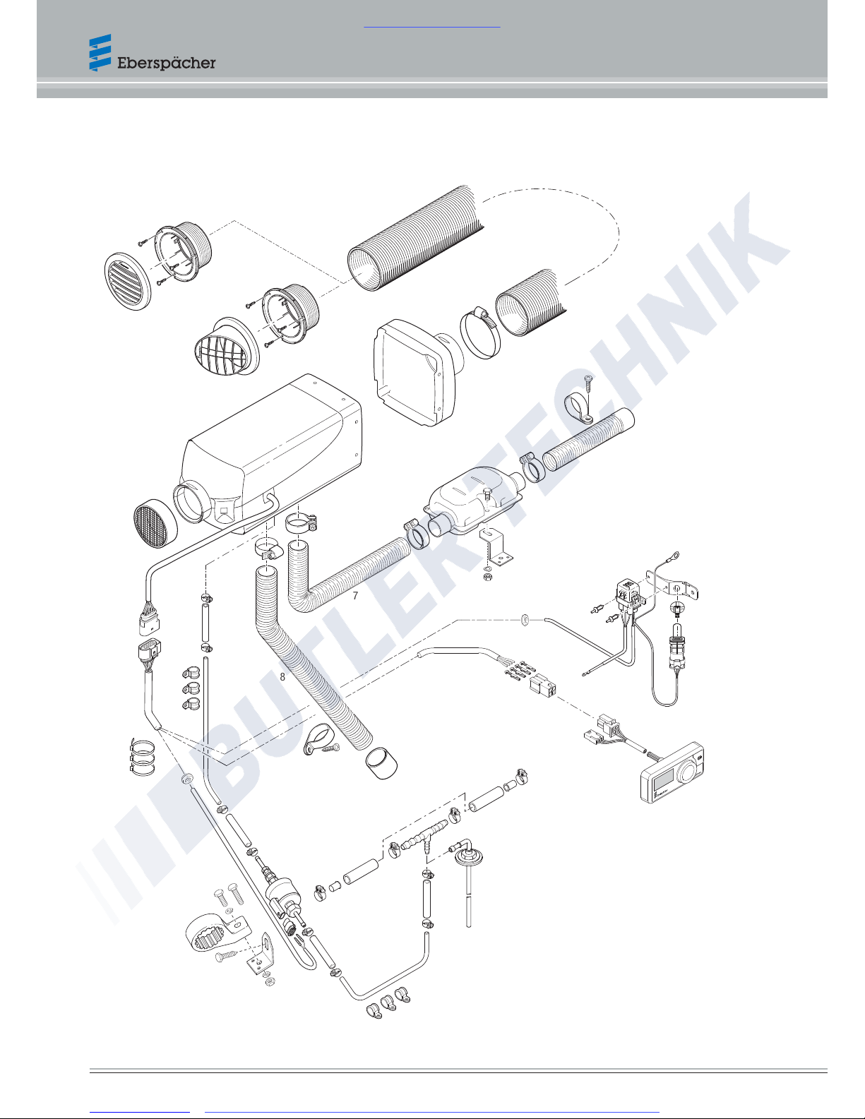
2.3 Scope of supply – heater, installation kit and additional parts
21
7
22
9
8
10
11
A
C
B
14
12
18
1
19
13
20
6
5
23
2
4*
25
15
17
16
* To be ordered separately
Technical Description | Airtronic S2 / M2
10 25.2720.90.0001.0A EN | 02.2018
www.butlertechnik.com
Visit us www.butlertechnik.com for more technical information and downloads
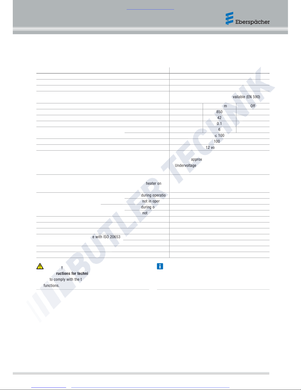
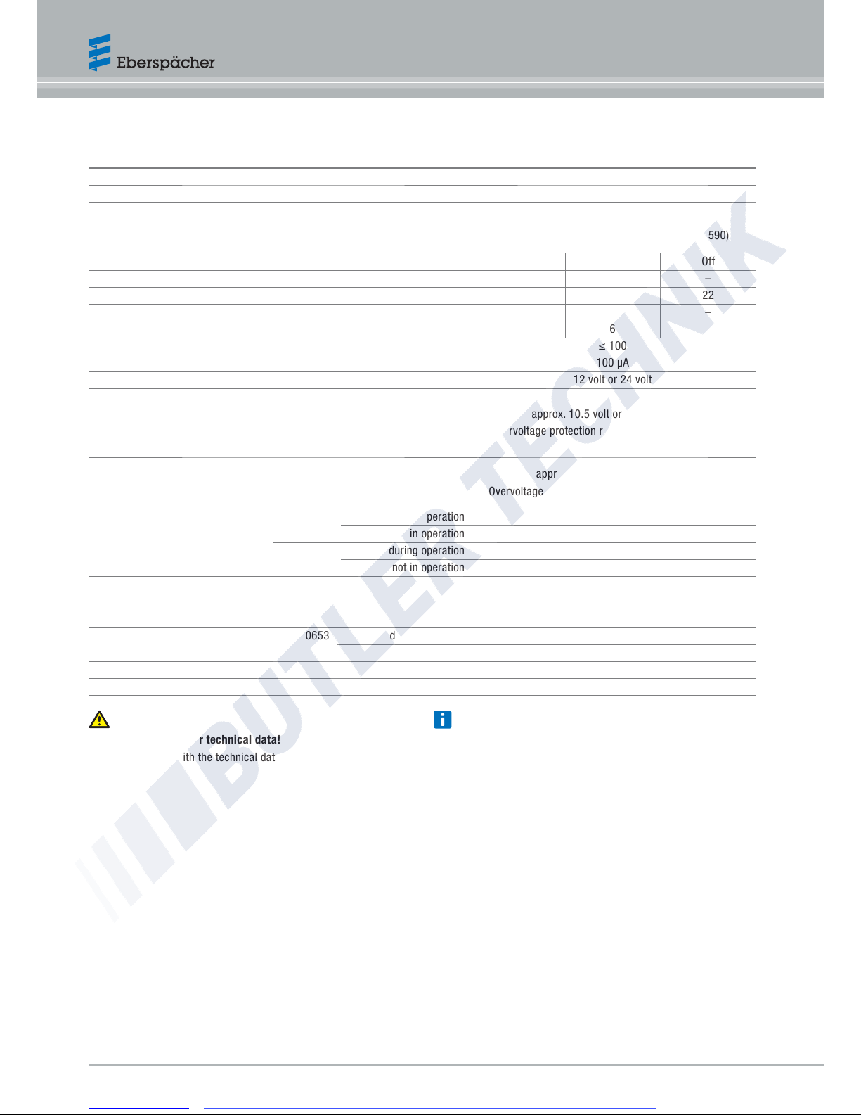
2.4 Technical data
2.4.1 Airtronic S2 D2L
Heater type Airtronic
Heater Airtronic S2
Version D2L
Heating medium Air
Fuel
“Fuel quality” and “Fuel at low temperatures”on page25.
Diesel – standard commercially available (EN 590)
Control of the heat flow
Maximum Minimum Off
Heat flow (watt)
2200 850 –
Hot air throughput without backpressure (kg/h) with hood 75mm
105 42 13
Fuel consumption (l/h)
0.28 0.1 –
Average electrical power consumption (watt) during operation
31 6 4
while starting ≤100
Closed-circuit power consumption 100μA
Rated voltage 12volt or 24volt
Operating range
Lower voltage limit:
Undervoltage protection installed in the control box switches off the heater on
reaching the voltage limit.
approx. 10.5volt or approx. 21volt
Undervoltage protection response time: 20seconds ±1
Upper voltage limit:
Overvoltage protection installed in the control box switches off the heater on
reaching the voltage limit.
approx. 16volt or approx. 32volt
Overvoltage protection response time: 20seconds ±1
Ambient temperature Heater during operation –40°C to +70°C
not in operation –40°C to +85°C
Metering
pump
during operation –40°C to +50°C
not in operation
–40°C to +125°C
Hot air intake temperature max. +40°C
Combustion air temperature max. +50°C
Interference suppression Suppression class 5 to EN 55025
Degree of protection in accordance with ISO20653 during operation IP5k4k
not in operation IP5k6k and IP5k9k
Weight approx. 2.7kg
Ventilation mode possible
Attention! Note
Safety instructions for technical data!
Failure to comply with the technical data can result in
malfunctions.
Provided no other values are given, the technical data provided is
with the usual tolerances of ±10% at rated voltage, 20°C ambient
temperature and reference altitude Esslingen.
Technical Description | Airtronic S2 / M2
25.2720.90.0001.0A EN | 02.2018 11
www.butlertechnik.com
Visit us www.butlertechnik.com for more technical information and downloads
2.4.2 Airtronic M2 D4L
Heater type Airtronic
Heater Airtronic M2
Version D4L
Heating medium Air
Fuel
“Fuel quality” and “Fuel at low temperatures”on page25.
Diesel – standard commercially available (EN 590)
Control of the heat flow
Maximum Minimum Off
Heat flow (watt)
4000 900 –
Hot air throughput without backpressure (kg/h) with hood 90mm
180 60 22
Fuel consumption (l/h)
0.51 0.11 –
Average electrical power consumption (watt) during operation
42 6 5
while starting ≤100
Closed-circuit power consumption 100μA
Rated voltage 12volt or 24volt
Operating range
Lower voltage limit:
Undervoltage protection installed in the control box switches off the heater on
reaching the voltage limit.
approx. 10.5volt or approx. 21volt
Undervoltage protection response time: 20seconds ±1
Upper voltage limit:
Overvoltage protection installed in the control box switches off the heater on
reaching the voltage limit.
approx. 16volt or approx. 32volt
Overvoltage protection response time: 20seconds ±1
Ambient temperature Heater during operation –40°C to +70°C
not in operation –40°C to +85°C
Metering
pump
during operation –40°C to +50°C
not in operation
–40°C to +125°C
Hot air intake temperature max. +40°C
Combustion air temperature max. +50°C
Interference suppression Suppression class 5 to EN 55025
Degree of protection in accordance with ISO20653 during operation IP5k4k
not in operation IP5k6k and IP5k9k
Weight approx. 4.5kg
Ventilation mode possible
Attention! Note
Safety instructions for technical data!
Failure to comply with the technical data can result in
malfunctions.
Provided no other values are given, the technical data provided is
with the usual tolerances of ±10% at rated voltage, 20°C ambient
temperature and reference altitude Esslingen.
Technical Description | Airtronic S2 / M2
12 25.2720.90.0001.0A EN | 02.2018
www.butlertechnik.com
Visit us www.butlertechnik.com for more technical information and downloads
 Loading...