

Eberspächer HYDRONIC S3 Installation Recommendations

VEHICLE HEATERS | TECHNICAL DOCUMENTATION
INSTALLATION RECOMMENDATIONS
EN
HYDRONIC S3 – B 5 E IN THE DODGE RAM
SPARE PARTS LIST
REPAIR INSTRUCTIONS
TECHNICAL DESCRIPTION
INSTALLATION RECOMMENDATION
THIS INSTALLATION RECOMMENDATION APPLIES TO VEHICLES FROM MODEL YEAR 2017 WITH
THE FOLLOWING MOTORISATION:
5.7 l cubic capacity / 8 cylinder V-engine / 295 kW - 401 HP (HSN: 1726)
A WORLD OF COMFORT

VEHICLE HEATERS – TECHNICAL DOCUMENTATION | 2
CONTENTS
CHAPTER CHAPTER DESCRIPTION PAGE
1 Introduction 3-5
2 Preparation of the vehicle 7
3 Preliminary assembly 8-15
4 Installation 16-31
5 After installation 32
6 Parts Overview 33
Initial commissioning EasyStart Timer 34-35
Diagnostics 36
Leaflet for the Customer 37
This installation recommendation documents the installation of the Hydronic S3 heater in a vehicle from model year
2017 with the following equipment:
with 2-zone automatic AirCon
with fog lamps
with daytime running lights
with LED headlights
with automatic gearbox
with four-wheel drive 4 x 4
with or without Prins LPG system
not tested:
manual air-conditioning
PLEASE NOTE!
This installation recommendation is valid for the above mentioned vehicle to the exclusion of all liability claims.
Deviating model years and/or deviating equipment may result in modifications to this installation recommendation.
It is therefore mandatory to check the feasibility of installing the heater in the vehicle before starting work.
All liability claims resulting from modifications to the vehicle are excluded.
Installation time: approx. 7 hours
1 INTRODUCTION
VEHICLE HEATERS – TECHNICAL DOCUMENTATION | 3
SPECIAL TEXT FORMATS, PRESENTATIONS AND PICTURE SYMBOLS
In this installation recommendation, special text formats and picture
symbols are used to emphasise different contents. Please refer to the
following examples for their meanings and appropriate action.
SPECIAL TEXT FORMATS AND PRESENTATIONS
This dot () denotes a list, which is started by a heading.
– If an indented dash (–) follows a “dot”, this list is a sub-section of
the black dot.
PICTURE SYMBOLS
DANGER!
This information points out a potential serious or fatal danger. Ignoring
this information can result in severe injuries.
Î This arrow indicates the appropriate precaution to take to avert the
danger.
CAUTION!
This information points out a dangerous situation for a person and / or
the product. Ignoring this information can result in injuries to people
and / or damage to machinery.
Î This arrow indicates the appropriate precaution to take to avert the
danger.
PLEASE NOTE!
These remarks contain recommendations for use and useful tips for the
operation, installation and repair of the heater.
SAFETY INSTRUCTIONS FOR INSTALLATION AND REPAIR
DANGER!
Improper installation or repair of Eberspächer heaters can cause a fire
or result in toxic exhaust entering the inside of the vehicle.
This can cause serious and even fatal risks.
Î Only authorised and trained persons may install the heater accord-
ing to the specifications in the technical documents or repair it
using original spare parts.
Î Installation and repairs by unauthorised and untrained persons,
repairs using non-original spare parts and without the technical
documents required for installation and repair are dangerous and
therefore are not permitted.
Î Installation according to this installation recommendation may only
be carried out in conjunction with the respective unit-related tech-
nical description, installation instructions, operating instructions
and maintenance instructions.
This document must be carefully read through before / during
installation and repair and followed throughout. Particular attention
is to be paid to the official regulations, the safety instructions and
the general information.
PLEASE NOTE!
The relevant rules of sound engineering practice and any information
provided by the vehicle manufacturer are to be observed during the
installation and repair.
When carrying out electric welding on the vehicle, the positive cable
at the battery should be disconnected and earthed to protect the
control box.
LIABILITY CLAIM / WARRANTY
Eberspächer does not accept any liability for defects and damage,
which are due to installation or repair by unauthorised and untrained
persons.
Compliance with the official regulations and the safety instructions is
prerequisite for liability claims.
Failure to comply with the official regulations and safety instructions
leads to exclusion of any liability of the heater manufacturer.
ACCIDENT PREVENTION
General accident prevention regulations / health and safety regulations
and the corresponding workshop, company and operating safety
instructions are to be observed.

1 INTRODUCTION
VEHICLE HEATERS – TECHNICAL DOCUMENTATION | 4
ADDITIONAL INFORMATION ON THE VALIDITY OF THE INSTALLATION
RECOMMENDATION
The installation recommendation is valid for the vehicle with the engine
and gearbox options listed in the following.
ENGINE AND GEARBOX OPTIONS
Cubic capacity kW / HP Gearbox
5.7 l V8 295 / 401 AT
AT = automatic transmission
PLEASE NOTE!
The installation recommendation is not valid for right-hand drive
vehicles.
Vehicle models, engine types and feature options not listed in this
installation recommendation, have not been tested.
Installation according to this installation recommendation can still be
possible.
INITIAL STARTUP OF THE HEATER OR FUNCTIONAL TEST
After installation or carrying out a repair on the heater, the coolant
circuit and the whole fuel supply system must be carefully vented.
Comply with the instructions issued by the vehicle manufacturer.
Open all heating circuits before the trial run (set the temperature
controller to “hot”).
During the heater trial run, all water and fuel connections must be
checked for leaks and secure, tight fit.
If faults occur while the heater is running, use a diagnostic unit to
correct the cause of the fault.
PARTS REQUIRED FOR INSTALLATION
QUANTITY DESIGNATION ORDER NO.
1 Hydronic S3 - B 5 E 20 1952 05 00 00
1 Vehicle-specific installation kit 24 8000 35 00 19
EasyStart control unit as chosen:
1 EasyStart Timer 22 1000 34 15 00
SPECIAL TOOLS REQUIRED
Necessary torque wrench
Anti-corrosion agent
Crimping tool
Pliers for spring band clamps
TIGHTENING TORQUES
If no tightening torques are specified, tighten the screw connections
according to the following table:
Part name Tightening torques
+0.5
+0.5
+1
+0.5
+0.5
+0.2
+1
+2
+2
+1
+0.5
Nm
Nm
Nm
Nm
Nm
Nm
Nm
Nm
Nm
Nm
Nm
Hex screw M6 10
Hex screw M8 20
Hex screw M10 45
Self-tapping M6 x 16 Torx screw 11
Screw M4 3
Screw M5 x 10 5
Screw M5 x 18 6.5
Pipe clip for exhaust pipe 7
Hose clip for water hose 3
Hose clip for combustion air pipe 5
Hose clip for fuel pipe 1
1 INTRODUCTION
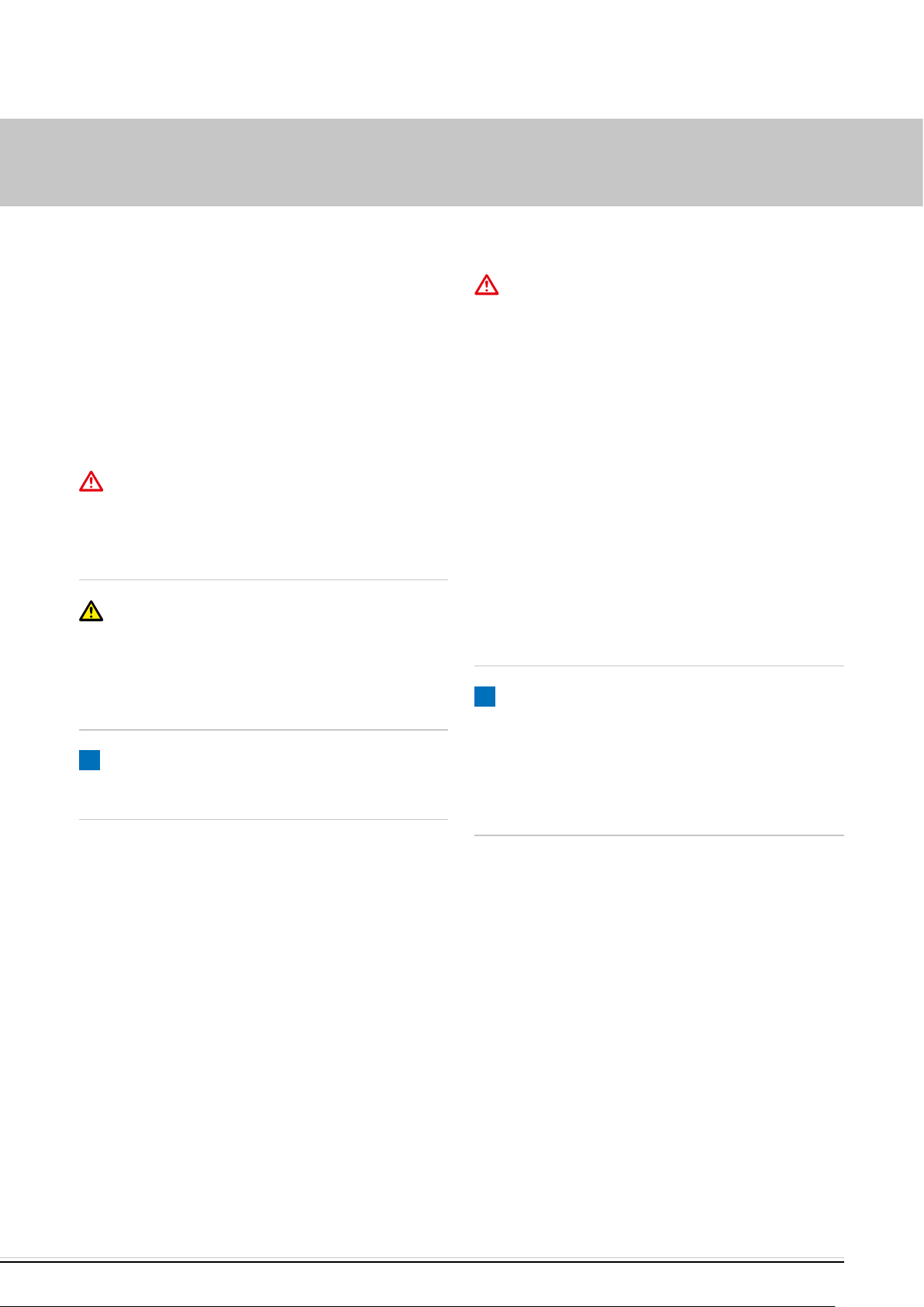
INSTALLATION DRAWING
4
1
VEHICLE HEATERS – TECHNICAL DOCUMENTATION | 5
7
3
5
6
8
1 Heater Hydronic S3
2 Water pump
3 Exhaust pipe with exhaust silencer
4 Combustion air tube
5 Fuse holder
6 Fan control box “EasyFan”, fan relay and isolating relay
7 Stationary
8 Button
9 Metering pump
10 Tank extractor
10
9
2 PREPARATION OF THE VEHICLE
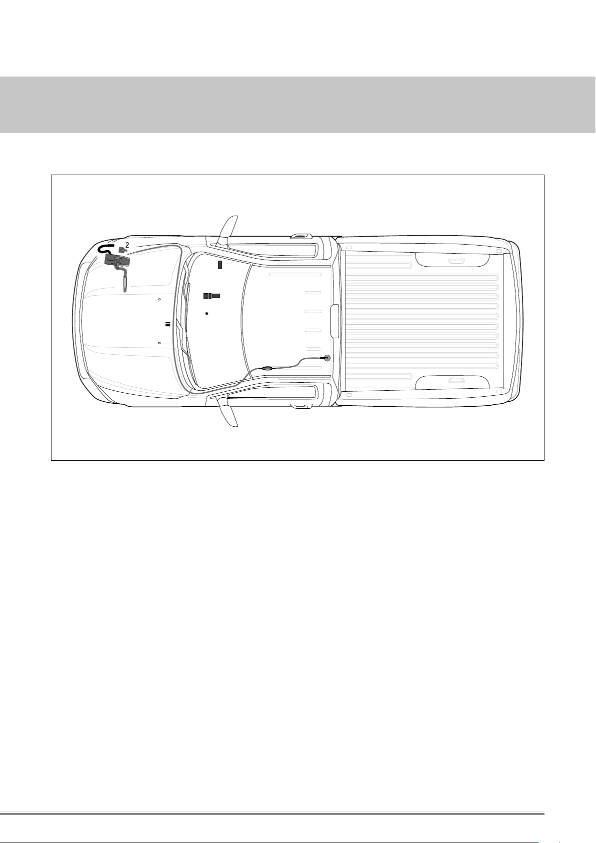
PREPARATORY WORK ON THE VEHICLE
VEHICLE HEATERS – TECHNICAL DOCUMENTATION | 6
Disconnect the battery
Remove glove compartment
Remove top shelf
Remove air filter housing
Remove front right-hand wheel
(see photo 1)
Detach the retaining cable of the glove compartment out to the back.
Detach the glove compartment from the fastening points and remove.
Remove right-hand, front wheel arch liner
Remove lower gearbox cowling
Remove tank according to the manufacturer's instructions
Depressurise the cooling system
Drain coolant into a clean container
a
Fig. 1
a Glove compartment
b Detach retaining cable
b
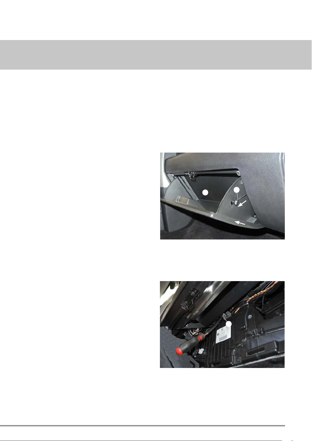
INSTRUCTIONS FOR REMOVING THE TOP SHELF
(see photos 2 to 4)
Unscrew the M4 screw of the top shelf.
a
Fig. 2
a Loosen M4 screw of top shelf
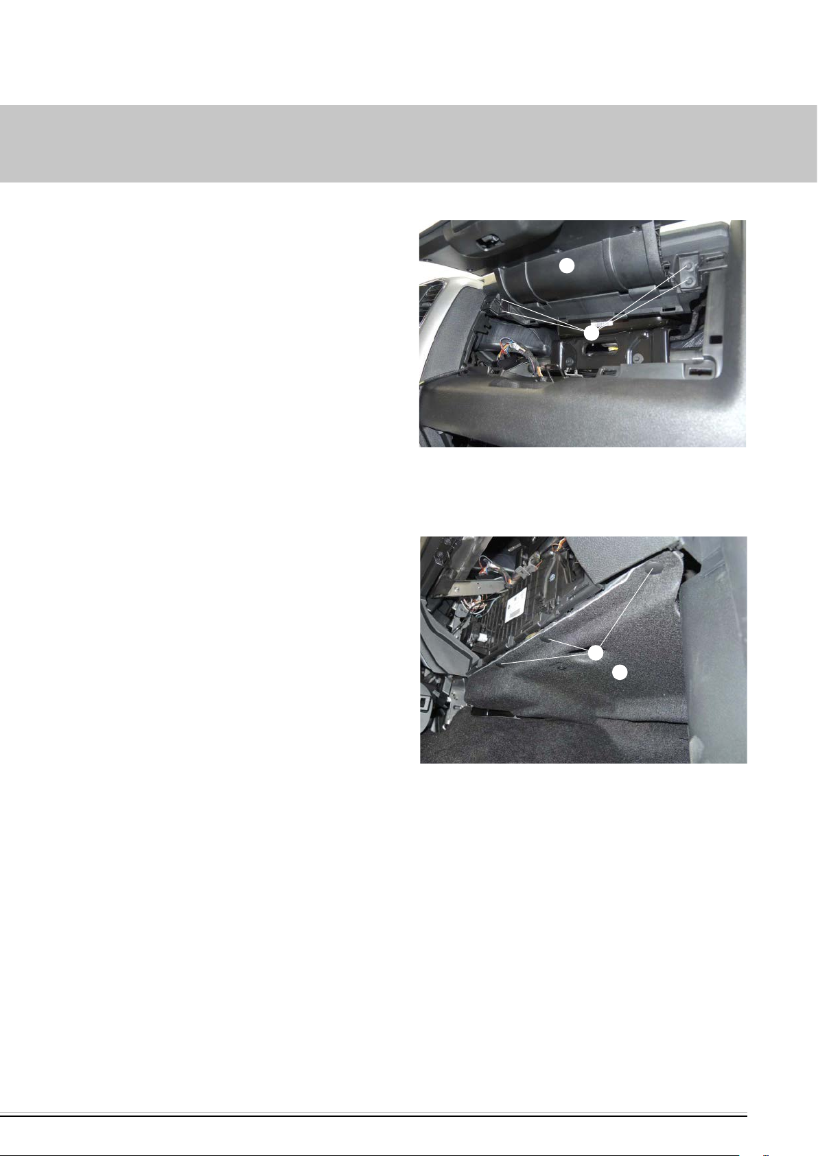
2 PREPARATION OF THE VEHICLE
Unscrew the four fastening screws of the top shelf and remove the
shelf.
VEHICLE HEATERS – TECHNICAL DOCUMENTATION | 7
a
b
Loosen the fastening clips of the lower trim moulding and remove the
trim moulding.
Fig. 3
a Upper shelf
b Loosen 4x fastening screw of the top shelf
b
a
Fig. 4
a Remove lower trim moulding of glove compartment
b Loosen fasten clips of lower trim moulding

3 PRELIMINARY ASSEMBLY
PREPARE HEATER
(see photos 5 and 6)
Mount the angled water connection socket to the heater as shown, see
“Assembly Steps”.
Remove the duplicate nameplate from the heater.
VEHICLE HEATERS – TECHNICAL DOCUMENTATION | 8
a
Fig. 5
a Heater
b Mount elbow connection
b
Installation steps
Grease the O-ring (5) and insert in the groove at the connection
socket.
Fit the connection socket (3 or 4) in the cut-outs of the sensor cover
(2). The collar of the connection socket is above the cover.
Position the connection socket with the gearing in the sensor cover
and fix accordingly.
Fit the sensor cover on the heater with the connection socket point-
ing forwards.
Press the connection socket completely into the corresponding holes
on the heat exchanger.
Adjust the direction for the angled connection socket:
– Raise the sensor cover up to the collar of the connection socket
– Turn the connection socket in the required direction
– Push the sensor cover down and readjust the position of the con-
nection socket so that the toothed edges engage again
Fasten sensor cover with M5 x 18 (1) screw
(tightening torque 6.5
+0.5
Nm).
Fig. 6
1 M5 x 18 screw 4 Angled connection socket
2 Sensor cover 5 O-ring
3 Connection socket, straight
3 PRELIMINARY ASSEMBLY
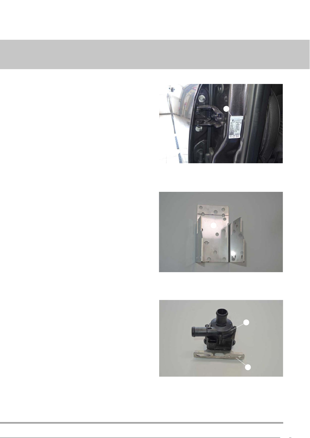
ADHERE DUPLICATE NAMEPLATE
(see photo 7)
VEHICLE HEATERS – TECHNICAL DOCUMENTATION | 9
Fit the duplicate nameplate to the B-pillar on the passenger side as
shown.
PREPARE HEATER BRACKET
(see photo 8)
Prepare the already premounted heater bracket for subsequent
installation.
a
a
Fig. 7
a Fit duplicate nameplate
a
PREMOUNT WATER PUMP
(see photo 9)
Insert the water pump in the water pump holder.
Fig. 8
a Heater bracket
b
a
Fig. 9
a Holder, water pump
b Water pump
3 PRELIMINARY ASSEMBLY
300
300
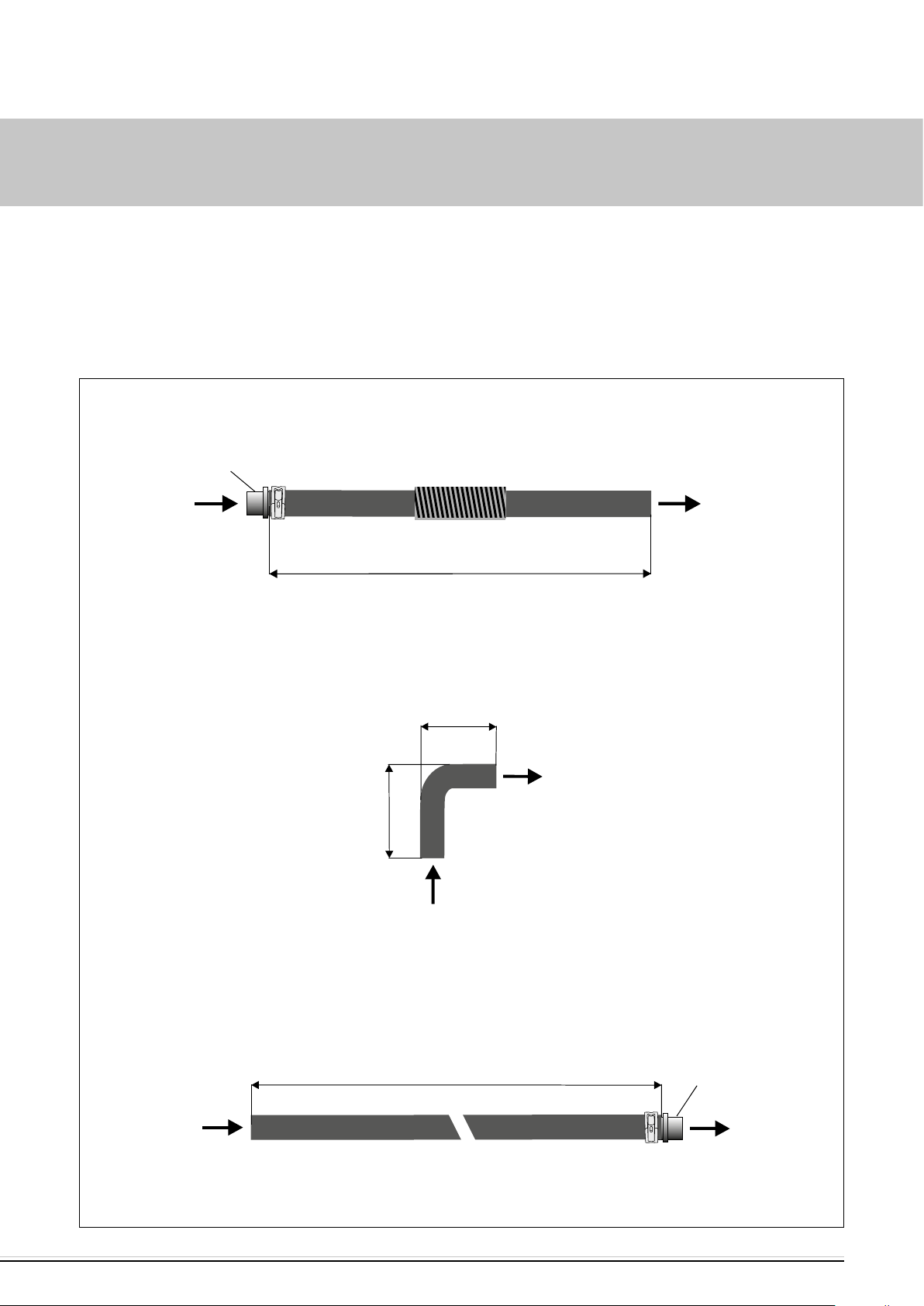
PREPARE WATER HOSES
(see photos 10 to 13)
For vehicles without Prins LPG system
The water hoses are already prepared as shown.
Reducer
20/15 mm
VEHICLE HEATERS – TECHNICAL DOCUMENTATION | 10
Water hose 1
from engine to water pump
Engine
Water pump
Water hose 2
from water pump to heater
55
Heater
70
Water pump
Fig. 10
Heater
Water hose 3
from heater to heat exchanger
Reducer
20/15 mm
Heat exchanger
3 PRELIMINARY ASSEMBLY
270
90
300
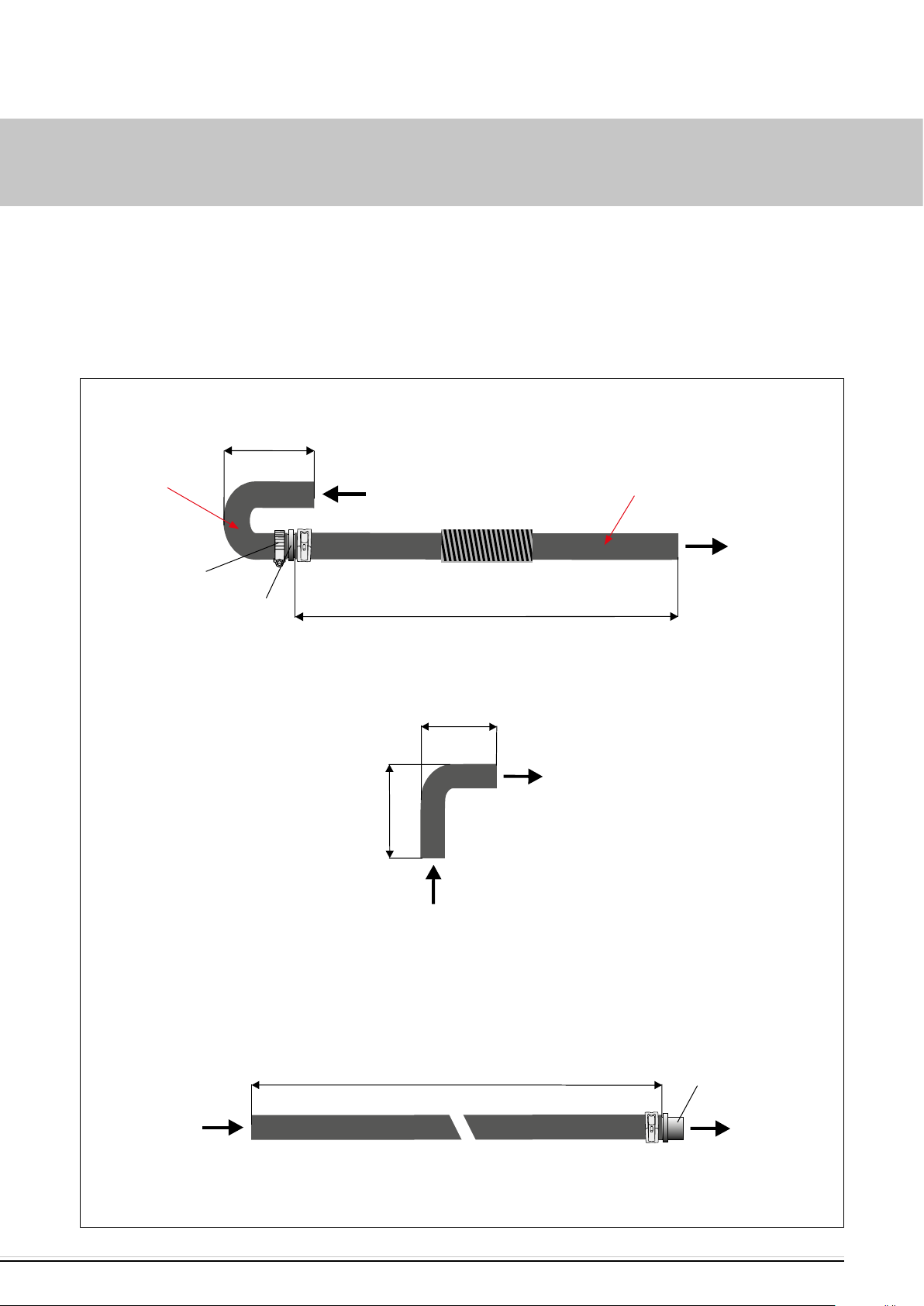
PREPARE WATER HOSES
For vehicles with Prins LPG system
Prepare water hoses as shown.
Mount 180°
water hose
bend, Ø 15mm
Engine
VEHICLE HEATERS – TECHNICAL DOCUMENTATION | 11
Water hose 1
from engine to water pump
Shorten the
water hose to
L=270 mm
Hose clip,
16 - 25 mm Ø
Water pump
Reducer
20/15 mm
Water hose 2
from water pump to heater
55
Heater
70
Water pump
Water hose 3
from heater to heat exchanger
Fig. 11
Heater
Reducer
20/15 mm
Heat exchanger
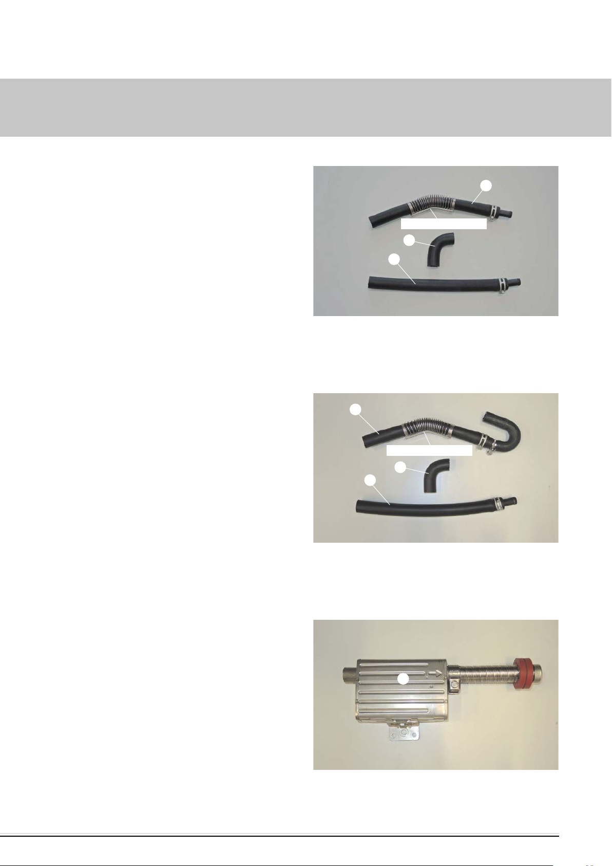
3 PRELIMINARY ASSEMBLY
For vehicles without Prins LPG system
The figure shows the premounted water hoses 1 to -3.
VEHICLE HEATERS – TECHNICAL DOCUMENTATION | 12
a
Shape water hose 1 with the hose bending device (Unicoil) at the bend-
ing edge as shown.
For vehicles with Prins LPG system
The figure shows the premounted water hoses 1 to -3.
Shape water hose 1 with the hose bending device (Unicoil) at the bend-
ing edge as shown.
Unicoil bending edge
b
c
Fig. 12
a Water hose 1
b Water hose 2
c Water hose 3
a
Unicoil bending edge
b
c
PREPARE EXHAUST SILENCER
(see photo 14)
Prepare the already premounted exhaust silencer for subsequent
installation.
Fig. 13
a Water hose 1
b Water hose 2
c Water hose 3
a
Fig. 14
a Premounted exhaust silencer
 Loading...