

Eberspächer Hydronic M-II, Hydronic M8 Biodiesel, Hydronic M12, Hydronic M10 Technical Description, Installation, Operation And Maintenance Instructions

HYDRONIC M-II
Technical description, installation,
operation and maintenance instructions.
Heater Order no.
Hydronic M8 Biodiesel 12 V 25 2470 05 00 00
24 V 25 2471 05 00 00
Hydronic M10 12 V 25 2434 05 00 00
24 V 25 2435 05 00 00
Heater Order no.
Hydronic M12 12 V 25 2472 05 00 00
24 V 25 2473 05 00 00
Water heater for diesel,
operating independently of the engine.
25 2435 90 99 80
08.2009

2
1
Introduction
Contents
Chapter
1
2
3
4
5
6
7
8
Title
Introduction
Product information
Installation
Operation and
function
Electrical system
Troubleshooting
Maintenance
Service
Environment
Lists
Contents
• Contents...................................................................................................... 2
• Concept of this manual ................................................................................ 3
• Special text structure, presentation and picture symbols ..............................4
• Important information before starting work ................................................... 4
• Statutory regulations ................................................................................ 5, 6
• Safety instructions for installation and operation .......................................... 7
• Accident prevention .................................................................................... 7
• Scope of supply ...................................................................................... 8, 9
• Technical data.................................................................................... 10 – 12
• Main dimensions ........................................................................................ 13
• Installation location ....................................................................................14
• Installing the 24 V heater in a vehicle for the transport of
dangerous goods as per ADR / ADR 99 .................................................... 14
• Possible installation positions ..................................................................... 15
• Mounting and fastening .............................................................................15
• Nameplate ................................................................................................. 16
• Connection to the cooling water circuit .............................................. 17 – 20
• Exhaust system ........................................................................................ 21
• Combustion air system .............................................................................. 22
• Fuel supply ........................................................................................ 23 – 27
• Operating instructions ............................................................................... 28
• Initial commissioning .................................................................................. 28
• Important information for operation ............................................................ 28
• Description of functions .............................................................................28
• Control and safety devices / EMERGENCY OFF ........................................ 29
• Heater wiring .............................................................................................30
• Parts list for the circuit diagrams .................................................... 30, 33, 35
• Circuit diagrams..................................................................... 31, 34, 36 – 39
• In case of faults, please check the following points ...................................40
• Troubleshooting ......................................................................................... 40
• Maintenance instructions ........................................................................... 40
• Service ......................................................................................................40
• Certification ............................................................................................... 41
• Disposal .................................................................................................... 41
• EU Declaration of Conformity ..................................................................... 41
• List of key words ................................................................................. 42, 43
• List of abbreviations ................................................................................... 43

3
1
Introduction
Concept of this manual
This manual aims to support the service company
installing the heater and to provide the user with all
important information about the heater.
The manual has been divided into 8 chapters to make
it easier to find the corresponding information quickly.
Introduction
1
Here you will find important introductory information about installation of the heater and about the
structure of the manual.
Product information
2
Here you will find information about the scope of
supply, the technical data and the dimensions of
the heater.
Installation
3
Here you will find important information and instructions referring to installation of the heater.
Operation and function
4
Here you will find information about the operation
and function of the heater.
Electric system
5
Here you will find information about the electronic
system and electronic components of the heater.
Troubleshooting / maintenance / service
6
This section contains information on possible
faults and malfunctions, troubleshooting, maintenance and the service hotline.
Environment
7
Here you will find information about certification
and disposal of the heater together with the EU
Declaration of Conformity.
Lists
8
Here you will find the key word list and abbreviations list.
4
1
Introduction
Special text structure, presentation and
picture symbols
This manual uses special text structures and picture
symbols to emphasise different contents.
Please refer to the examples below for the corresponding meanings and associated actions.
Special structure and presentations
A dot (•) indicates a list which is started by a heading. If
an indented dash (–) follows a dot, this list is subordinate to the dot.
Picture symbols
Regulation!
This picture symbol with the remark “Regulation” refers
to a statutory regulation. Failure to comply with this regulation results in expiry of the type permit for the heater
and preclusion of any guarantee and liability claims on J.
Eberspächer GmbH & Co. KG.
Danger!
This picture symbol with the remark “Danger!” refers to
the risk of a fatal danger to life and limb. Under certain
circumstances, failure to comply with these instructions
can result in severe or life-threatening injuries.
Caution!
This picture symbol with the remark “Caution!” refers to
a dangerous situation for a person and/or the product.
Failure to comply with these instructions can result in
injuries to people and / or damage to machinery.
Please note!
These remarks contain application recommendations
and useful tips for installation of the heater.
Important information before starting work
Range of application of the heater
The water heater operating independently of an engine
is intended for installation in the following vehicles,
depending on its heating output:
• Vehicles of all kinds
• Construction machinery
• Agricultural machinery
• Boats, ships and yachts
Please note!
• Installation of the heater is permitted in vehicles used
for the transport of dangerous goods as per ADR.
• The heater is not approved for installation in vehicle
compartments used by persons (more than 8 passenger spaces) in Class M2 and M3 vehicles (vehicles for
the transport of passengers / commercial buses).
• The heater is not approved for installation in the driver
or passenger compartments of Class M1 vehicles
(vehicles for the transport of passengers / cars) and
Class N vehicles (vehicles for the transport of goods).
On account of its functional purpose, the heater is not
permitted for the following applications:
• Long-term continuous operation, e.g. for pre-heating
and heating of:
– Residential rooms
– Garages
– Work huts, weekend homes and hunting huts
– Houseboats, etc.
Caution!
Safety instructions for application and proper
purpose
The heater must only be used and operated for the
range of application stated by the manufacturer in
compliance with the “Operating instructions” included
with every heater.

5
1
Introduction
Statutory regulations
The Federal Road Transport Directorate has issued an
“EC type approval“ and an “EMC type approval“ for
the heater for installation in motor vehicles and with
the following official type approval marks, noted on the
heater name plate.
Hydronic M-II EG- e1 00 0215
EMV- e1 035075
Regulation!
Directive 2001 / 56 / EU of the European Parliament and the Council
• Arrangement of the heater
– Parts of the structure and other components near
the heater must be protected from excess heat
exposure and possible contamination from fuel or
oil.
– The heater must not pose a fire hazard even when it
overheats.
This requirement is deemed to be fulfilled when
adequate clearance to all parts is observed during
installation, sufficient ventilation is provided and fireproof materials or heat plates are used.
– The heater may not be mounted in the passenger
compartment of Class M
A unit may however be used in a hermetically sealed
housing which also corresponds to the conditions
stated above.
– The factory nameplate or duplicate must be affixed
so that it can still be easily read when the heater is
installed in the vehicle.
– All appropriate precautions must be taken when
arranging the heater to minimise the risk of injuries
to persons or damage to other property.
and M3 vehicles.
2
• Fuel supply
– The fuel intake connection must not be located in
the passenger compartment and must be sealed
with a properly closing lid to prevent any fuel leaks.
– In heaters for liquid fuel where the heater fuel is
separate from the vehicle fuel, the type of fuel and
intake connection must be clearly identified.
– A warning sign is to be fixed to the intake connec-
tion indicating that the heater must be switched off
before refuelling.
• Exhaust system
– The exhaust outlet must be arranged so as to
prevent any penetration of exhaust fumes into the
vehicle interior through the ventilation system, warm
air intakes or open windows.
• Combustion air intake
– The air for the heater combustion chamber must not
be sucked in from the passenger compartment of
the vehicle.
– The air intake must be arranged or protected in such
a way that it cannot be blocked by other objects.
• Operating status display
– A clearly visible operating display in the user’s field of
vision must indicate when the heater is switched on
and off.

6
1
Introduction
Regulations
Additional regulations for certain vehicles
named in Directive 94 / 55 / EC (ADR Framework Directive)
Scope
This appendix applies to vehicles for which the special
provisions of Directive 94 / 55 / EC apply to combustion
heaters and their installation.
Definition of terms used
For the purposes of this appendix, the vehicle designations „EX / II“, „EX / III“, „AT“, „FL“ and „OX“ according
to Chapter 9.1 of Annex B of Directive 94 / 55 / EC are
used.
Technical regulations
General provisions (EX / II, EX / III, AT, FL and OX
vehicles)
Avoid heating and ignition
The combustion heaters and their exhaust gas routing
shall be designed, located, protected or covered so as
to prevent any unacceptable risk of heating or ignition
of the load. This requirement shall be considered as
fulfilled if the fuel tank and the exhaust system of the
appliance conform to provisions in 3.1.1.1 and 3.1.1.2.
Compliance with these regulations shall be checked in
the complete vehicle.
Fuel tanks
Fuel tanks for supplying the heater shall conform to the
following regulations:
• In the event of any leakage, the fuel shall drain to the
ground without coming into contact with hot parts of
the vehicle or the load;
• fuel tanks containing petrol shall be equipped with
an effective flame trap at the filler opening or with a
closure enabling the opening to be kept hermetically
sealed.
Exhaust system and exhaust pipe layout
The exhaust system as well as the exhaust pipes shall
laid out or protected to avoid any danger to the load
through heating or ignition. Parts of the exhaust system
situated directly below the fuel tank (diesel) shall have
a clearance of at least 100 mm or be protected by a
thermal shield.
Switching on the combustion heater
The combustion heater may only be switched on manually. Automatic switching on via a programmable switch
is not permitted.
EX / II and EX / III vehicles
Combustion heaters for gaseous fuels are not permitted.
FL vehicles
Combustion heaters must be able to be taken out of
service/disabled at least by the methods described in
the following:
a) Switching off manually in the driver‘s cabin
b) Switching off the vehicle‘s engine; in this case the
heater may be manually switched back on by the
vehicle driver;
c) Starting up of a feed pump installed in the vehicle for
the dangerous goods carried.
Combustion heater after-run
After-running of the switched off combustion heater
is permitted. In the cases named in the „FL vehicles“
paragraph under letters b) and c) the supply of combustion air must be interrupted by suitable means after a
maximum after-run period of 40 seconds. Only combustion heaters whose heat exchangers are verifiably not
damaged by the reduced after-run period of 40 seconds
beyond their usual use period may be used.
Please note!
• Compliance with the statutory regulations, the additional regulations and safety instructions is prerequisite
for guarantee and liability claims.
Failure to comply with the statutory regulations and
safety instructions and incorrect repairs even when
using original spare parts make the guarantee null
and void and preclude any liability for J. Eberspächer
GmbH & Co. KG.
• Subsequent installation of this heater must comply
with these installation instructions.
• The statutory regulations are binding and must also be
observed in countries which do not have any special
regulations.
• When the heater is to be installed in vehicles not
subject to the German Ordinance for the Registration
of Motor Vehicles (StVZO), for example ships, the
specially valid regulations and installation instructions
for these special applications must be observed.
• Installation of the heater in special vehicles must
comply with the regulations applying to such vehicles.
• Other installation requirements are contained in the
corresponding sections of this manual.
7
1
Introduction
Safety instructions for installation
and operation
Danger!
Risk of injury, fire and poisoning
• Disconnect the vehicle battery before starting any kind
of work.
• Before working on the heater, switch the heater off
and let all hot components cool down.
• The heater must not be operated in enclosed rooms,
e.g. in the garage or multi-storey car park.
Caution!
Safety instructions for installation and operation
• The heater must only be installed by a JE partner
authorised by the manufacturer according to the
instructions in this manual and possibly according
to special installation recommendations; the same
applies to any repairs to be carried out in the case or
repairs or guarantee claims.
• Repairs by non-authorised third-parties or with not
original spare parts are dangerous and therefore not
allowed. They result in expiry of the type permit of the
heater; consequently, when installed in motor vehicles
they can cause expiry of the vehicle operating licence.
• The following measures are not allowed:
– Changes to components relevant to the heater.
– Use of third-party components not approved by
J. Eberspächer GmbH & Co. KG.
– Nonconformities in installation or operation from the
statutory regulations, safety instructions or specifications relevant to safe operation as stated in the
installation instructions and operating instructions.
This applies in particular to the electrical wiring, fuel
supply, combustion air system and exhaust system.
• Only original accessories and original spare parts must
be used during installation or repairs.
• Only original accessories and spare parts may be
used for installation or repairs.
• Only the controls approved by Eberspächer may be
used to operate the heater. The use of other controls
can result in malfunctions.
• Before the heater is installed again in another vehicle,
rinse the heater parts carrying water with clear water.
• When carrying out electric welding on the vehicle, the
plus pole cable at the battery should be disconnected
and placed at ground to protect the controller.
• The heater must not be operated where there is a risk
of an accumulation of flammable vapours or dust, for
example close to
– fuel depot
– coal depot
– wood depot
– grain depots etc.
• The heater must be switched off when refuelling.
• When the heater is mounted in a safety housing etc.,
the installation compartment of the heater is not a
stowage compartment and must be kept clear.
In particular fuel canisters, oil cans, spray cans, gas
cartridges, fire extinguishers, cleaning rags, items of
clothing, paper etc. must not be stored or transported
on or next to the heater.
• Defect fuses must only be replaced by fuses with the
prescribed rating.
• If fuel leaks from the heater fuel system, arrange
for the damage to be repaired immediately by a JE
service partner.
• When topping up the coolant, only use the coolant
permitted by the vehicle manufacturer, see the vehicle
operating manual. Any blending with unpermitted
coolant can cause damage to the engine and heater.
• After-running of the heater must not be interrupted
prematurely e.g. by pressing the battery disconnecting
switch, apart from in the case of an emergency stop.
Accident prevention
General accident prevention regulations and the corresponding workshop and operation safety instructions
are to be observed.

8
2
Product information
Scope of supply
Quantity / Designation Order number
1 Hydronic M8 Biodiesel
12 Volt 25 2470 05 00 00
24 Volt 25 2471 05 00 00
To be ordered separately:
1 Universal installation kit 25 2435 80 00 00
1 Control unit* –
1 Hydronic M10
12 Volt 25 2434 05 00 00
24 Volt 25 2435 05 00 00
To be ordered separately:
1 Universal installation kit 25 2435 80 00 00
1 Control unit* –
1 Hydronic M12
12 Volt 25 2472 05 00 00
24 Volt 25 2473 05 00 00
To be ordered separately:
1 Universal installation kit 25 2435 80 00 00
1 Control unit* –
* Control units see price list / accessories catalogue..
Please note!
• The cable harness, Order No. 25 2435 80 06 00, is
also required for vehicles used for transporting dangerous goods.
• Please consult the additional parts catalogue if any
other parts are required for installation.
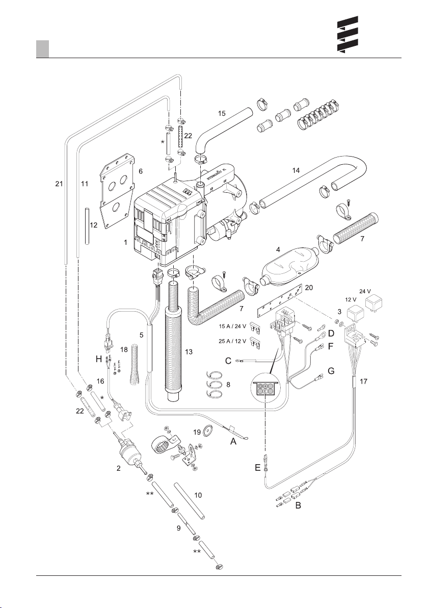
Parts list for the „Scope of supply“ figure on
page 9
Hydronic M8 Biodiesel heater scope of supply
Picture-No. Designation
1 Heater
2 Metering pump
21 Tube, Ø 6 x 1. length 6 m
22 Transition piece Ø 3.5 / 5, (2 x)
– Hose clamp Ø 10, (4 x)
Hydronic M10 / M12 heater scope of supply
Picture-No. Designation
1 Heater
2 Metering pump
Universal installation kit scope of supply
Picture-No. Designation
3 Relay 12 V / 24 V
4 Exhaust silencer
5 Cable tree, heater
6 Bracket, heater
7 Flexible exhaust pipe
8 Cable ties (10 x)
9 Pipe, Ø 6 x 1, length 1,5 m
10 Hose, Ø 5 x 3, length 0,5 m
11 Pipe, Ø 4 x 1, length 6 m
12 Hose, Ø 3,5 x 3, length 10 cm
13 Intake silencer for cumbustion air
14 Water hose
15 Water hose
16 Lead harness, metering pump
17 Lead harness, blower
18 Corrugated tube,
Inner Ø 10 mm, length 2 m
19 Grommet
20 Bracket
– Small parts
Cable harnesses
A „Controls“ lead harness
B „Blower control“ lead harness
C Positive cable
D Negative cable
E Connection, blower relay positive supply cable at
the fuse holder
F Connection at blower relay, terminal 85 (1-pole,
brown)
G Connection at blower relay, terminal 86 (1-pole,
red/yellow)
H Metering pump connection
9
2
Product information
Scope of supply
* make from Item 12
** make from Item 10
10
2
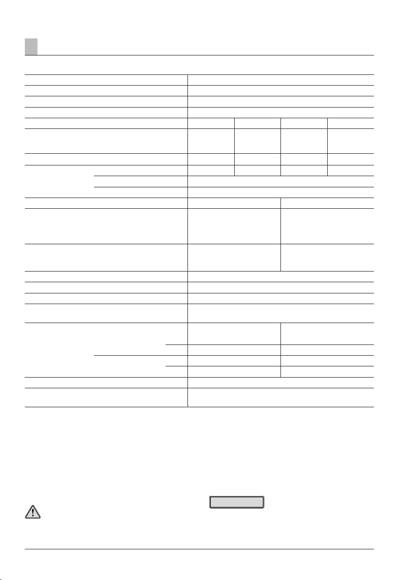
Product information
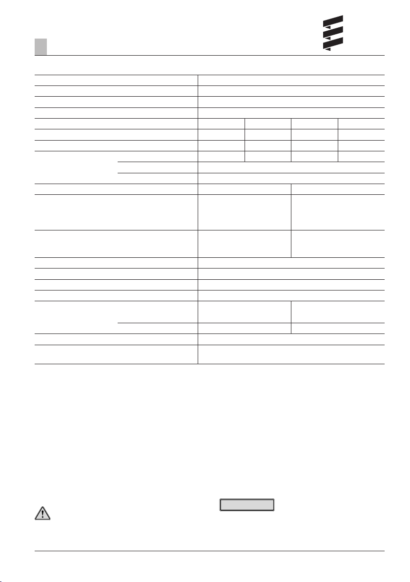
Technical data
Heater type
Heater Hydronic M8 Biodiesel
Version D 8 W
Heating medium Mixture of water and coolant (max. 50 % water, 50 % coolant)
Control of the heat flow Power Large Medium Small
Heat flow (watt)
Figures for operation with diesel fuel. If operated with FAME
the heat flow can reduce by up to 15 %.
Fuel consumption (l/h) 0.90 0.65 0.40 0.18
Electrical power (watt) in operation 55 46 39 35
at start – after 25 Sek. 200
in the control phase “OFF” 32
Rated voltage 12 Volt 24 Volt
Operating range
• Lower voltage limit: An undervoltage protection in
the controller switches the heater off on reaching the
voltage limit.
• Upper voltage limit: An overvoltage protection in the
controller switches the heater off on reaching the
voltage limit.
Tolerable operating pressure up to 2 bar overpressure
Flow rate of the water pump at 0.14 bar 1400 l/h
Minimum water flow rate of the heater 500 l/h
Fuel – see also “Fuel quality diesel heaters” page 27
Tolerable operating temperature Operation Not running
Heater / Control box
Dosing pump
Interference suppression class interference suppression class 5 to DIN EN 55 025
Weight with controller and water pump,
without dosing pump
Diesel –40 °C to +80 °C –40 °C to +85 °C
FAME –8 °C to +80 °C –40 °C to +85 °C
Diesel –40 °C to +50 °C –40 °C to +85 °C
FAME –8 °C to +50 °C –40 °C to +85 °C
8000 5000 3500 1500
10 Volt 20 Volt
15 Volt 30 Volt
Commercially available diesel (DIN EN 590)
FAME – for diesel engines according to DIN EN 14 214
Hydronic M-II
approx. 6.2 kg
Caution!
Safety instructions for technical data
Failure to comply with the technical data can result in
malfunctions.
Please note!
Provided no limit values are given, the technical data
listed is subject to the tolerances usually applicable to
heaters of ±10% for nominal voltage, ambient temperature 20 °C and reference altitude Esslingen.
11
2
Product information
Technical data
Heater type
Heater Hydronic M10
Version D 10 W
Heating medium Mixture of water and coolant (max. 50 % water, 50 % coolant)
Control of the heat flow Power Large Medium Small
Heat flow (watt) 9500 8000 3500 1500
Fuel consumption (l/h) 1.2 0.9 0.4 0.18
Electrical power (watt)(l/ in operation 86 60 39 35
at start – after 25 Sek. 120
in the control phase “OFF” 32
Rated voltage 12 Volt 24 Volt
Operating range
• Lower voltage limit: An undervoltage protection in
the controller switches the heater off on reaching the
voltage limit.
• Upper voltage limit: An overvoltage protection in the
controller switches the heater off on reaching the
voltage limit.
Tolerable operating pressure up to 2 bar overpressure
Flow rate of the water pump at 0.14 bar 1400 l/h
Minimum water flow rate of the heater 500 l/h
Fuel – see also “Fuel quality diesel heaters” page 27 Commercially available diesel (DIN EN 590)
Tolerable operating temperature Operation Not running
Heater / Control box –40 °C to +80 °C –40 °C to +85 °C
Dosing pump –40 °C to +50 °C –40 °C to +85 °C
Interference suppression class interference suppression class 5 to DIN EN 55 025
Weight with controller and water pump,
without dosing pump
10 Volt 20 Volt
15 Volt 30 Volt
Hydronic M-II
approx. 6.2 kg
Caution!
Safety instructions for technical data
Failure to comply with the technical data can result in
malfunctions.
Please note!
Provided no limit values are given, the technical data
listed is subject to the tolerances usually applicable to
heaters of ±10% for nominal voltage, ambient temperature 20 °C and reference altitude Esslingen.

12
2
Product information
Technical data
Heater type
Heater Hydronic M12
Version D 12 W
Heating medium Mixture of water and coolant (max. 50 % water, 50 % coolant)
Control of the heat flow Power Large Medium 1 Medium 2 Medium 3 Small
Heat flow (watt) 12000 9500 5000 3500 1500 1200
Fuel consumption (l/h) 1.5 1.2 0.65 0.40 0.18 0.15
Electrical power (watt)(l/) in operation 132 86 46 39 35 34
at start – after 25 Sek. 120
in the control phase “OFF” 32
Rated voltage 12 Volt 24 Volt
Operating range
• Lower voltage limit: An undervoltage protection in
the controller switches the heater off on reaching the
voltage limit.
• Upper voltage limit: An overvoltage protection in the
controller switches the heater off on reaching the
voltage limit.
Tolerable operating pressure up to 2 bar overpressure
Flow rate of the water pump at 0.14 bar 1400 l/h
Minimum water flow rate of the heater 500 l/h
Fuel – see also “Fuel quality diesel heaters” page 27 Commercially available diesel (DIN EN 590)
Tolerable operating temperature Operation Not running
Heater / Control box –40 °C to +80 °C –40 °C to +85 °C
Dosing pump –40 °C to +50 °C –40 °C to +85 °C
Interference suppression class interference suppression class 5 to DIN EN 55 025
Weight with controller and water pump,
without dosing pump
10 Volt 20 Volt
15 Volt 30 Volt
Hydronic M-II
approx. 6.2 kg
Caution!
Safety instructions for technical data
Failure to comply with the technical data can result in
malfunctions.
Please note!
Provided no limit values are given, the technical data
listed is subject to the tolerances usually applicable to
heaters of ±10% for nominal voltage, ambient temperature 20 °C and reference altitude Esslingen.
13
2
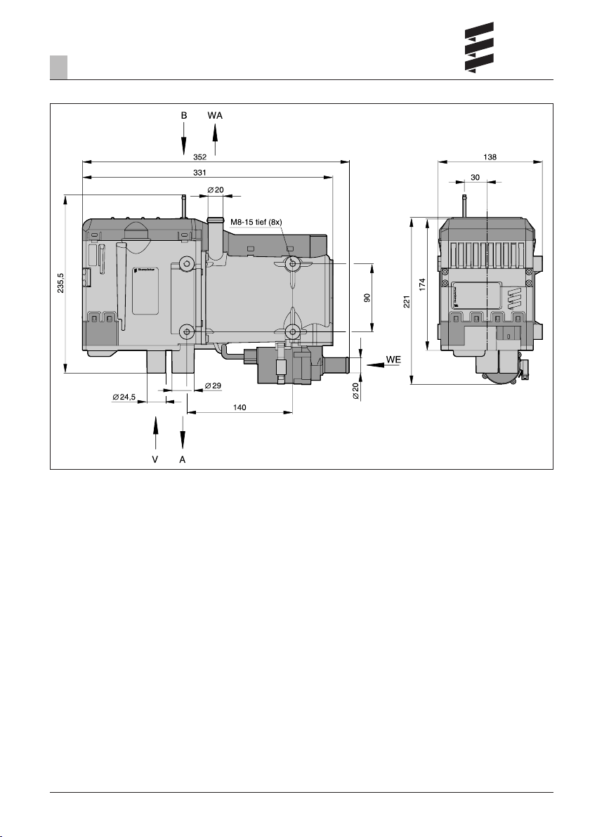
Product information
Main dimensions
A Exhaust
B Fuel
V Combustion air
WA Water outlet
WE Water inlet

14
3
Installation
Installation location
The installation location for the heater is the engine
compartment. The heater must be mounted below the
min. cooling water level (compensation tank, cooler, vehicle heat exchanger) for automatic venting of the heat
exchanger of the heater and the water pump.
Please note!
• In a truck, the water heater is preferably fastened
underneath the driver’s cab in the longitudinal beam
near the vehicle engine.
• The regulations and safety instructions to be observed
for this chapter are stated on page 4 – 7.
• The installation suggestions made in the installation
instructions are examples. Other installation locations
are possible if they correspond to the installation
requirements stated in these installation instructions.
• Other installation information (e.g. for boats and ships)
is available from the manufacturer on request.
• Please take note of the installation locations together
with the operating and storage temperatures.
Installation example heater in a truck
1 Heater
2 Exhaust pipe with exhaust silencer
3 Combustion air intake silencer
4 Fan relay
5 Fuse bracket
6 Controls
7 Dosing pump
8 Tank connection
Installing the 24 V heater in a vehicle for the
transport of dangerous goods as per ADR
For installation of the heater in vehicles for the transport
of dangerous goods, the regulations of
ADR / ADR99 must be observed.
With the appropriate electrical wiring the heater fulfils
the ADR regulations, see the “Additional Regulations” on
Page 6, the “Control and Safety Devices” on Page 29
and the “Circuit Diagrams” on Page 34 and 39.
Detailed information about the ADR regulations is contained in leaflet no. 25 2161 95 15 80.
 Loading...