

Eberspächer hydronic 16, hydronic 24, hydronic 30, hydronic 35 Troubleshooting And Repair Manual
J. Eberspächer
GmbH & Co.
Eberspächerstr. 24
D - 73730 Esslingen
Telephone (switchboard)
+49 (0)711 939 - 00
Fax
+49 (0)711 939 - 0500
www.eberspaecher.com
25 1818 95 14 86 04.2001 The information contained in this document is subject to change without notice. (s.e.e.o.) Printed in Germany © J. Eberspächer
Eberspächer
®
Technical Description
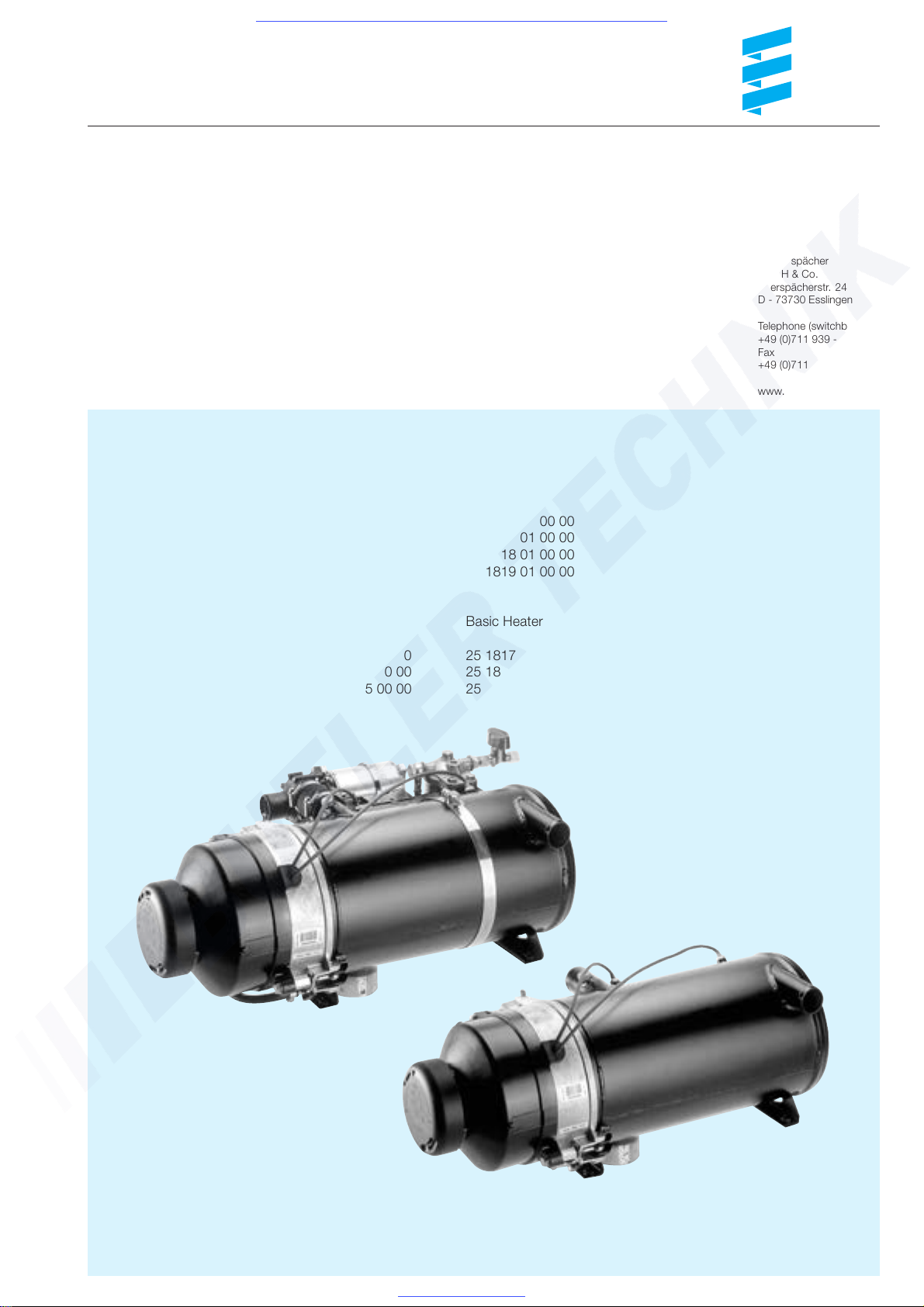
Troubleshooting and Repair Manual
Standard Model Cat. No. Basic Heater No.
HYDRONIC 16 - 24 V 25 2165 02 00 00 25 2165 01 00 00
HYDRONIC 24 - 24 V 25 1817 02 00 00 25 1817 01 00 00
HYDRONIC 30 - 24 V 25 1818 02 00 00 25 1818 01 00 00
HYDRONIC 35 - 24 V 25 1819 02 00 00 25 1819 01 00 00
Compact Model Cat. No. Basic Heater No.
HYDRONIC 24 - 24 V 25 1817 05 00 00 25 1817 01 00 00
HYDRONIC 30 - 24 V 25 1818 05 00 00 25 1818 01 00 00
HYDRONIC 35 - 24 V 25 2041 05 00 00 25 1819 01 00 00
This Troubleshooting and Repair Manual is valid for the following heater models:
Compact Model
Standard Model
HYDRONIC 16/24/30/35
*
Visit www.butlertechnik.com for more technical information and downloads.
www.butlertechnik.com
2
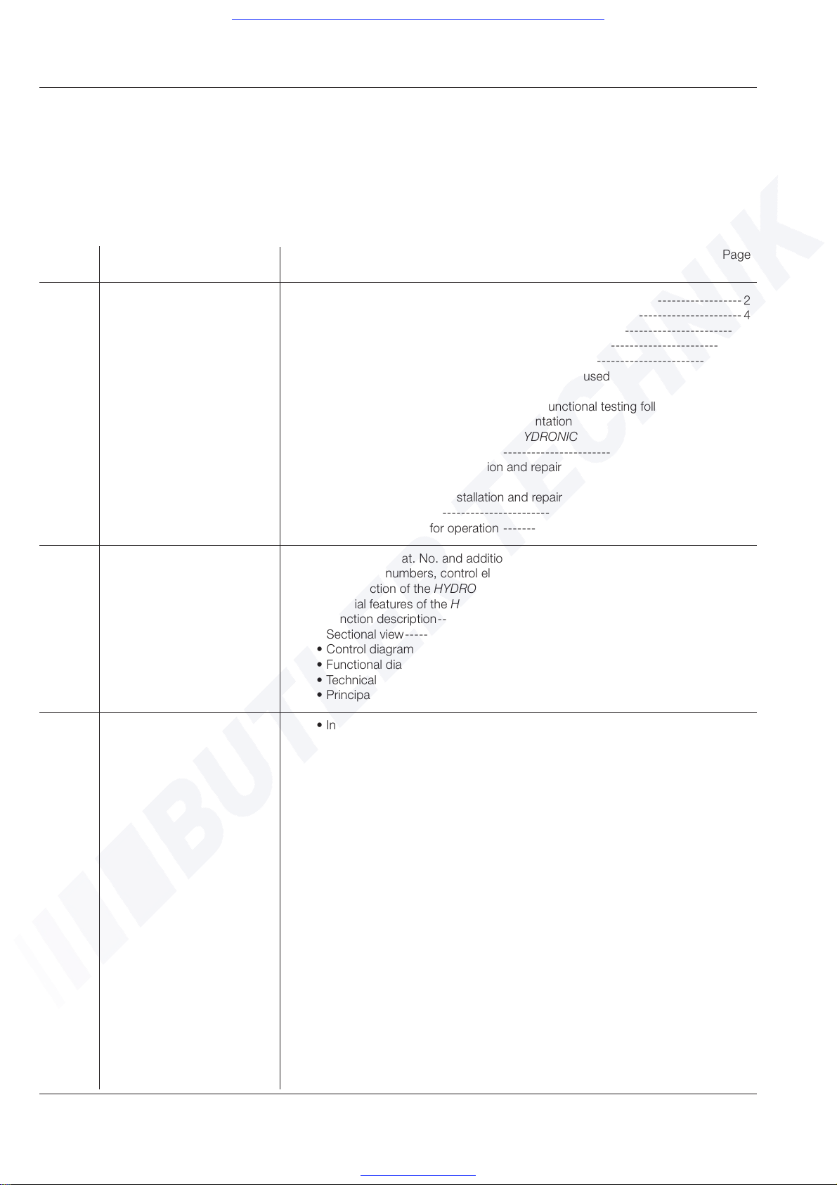
Table of Contents
This table of contents provides detailed information on the
contents of this Technical Description, Troubleshooting and
Repair Manual.
1 / Introduction
To find a term, use the index at the end of this document.
Chapter Title Content Page
No.
1 Introduction • Table of contents -------------------------------------------------------------------- 2
• Special notation, pictures and pictograms ----------------------------------------4
• Liability claims / warranty -----------------------------------------------------------7
• Accident prevention -----------------------------------------------------------------7
• Important information prior to commencing work-------------------------------- 5
- Applications in which the HYDRONIC may be used
- Intended use of the HYDRONIC
- Initial operation of the HYDRONIC and functional testing following a repair
- Content and purpose of this documentation
- Additional documentation on the HYDRONIC
• Statutory requirements-------------------------------------------------------------- 6
- Directions regarding installation and repair
- Directions for operation
• Safety instructions for installation and repair
of the HYDRONIC ------------------------------------------------------------------- 7
• Safety instructions for operation ---------------------------------------------------7
2 Product information • HYDRONIC Cat. No. and additional parts-------------------------------------- 8, 9
• Catalogue numbers, control elements------------------------------------------ 8, 9
• Construction of the HYDRONIC-------------------------------------------------- 10
• Special features of the HYDRONIC ---------------------------------------------- 10
• Function description--------------------------------------------------------------- 10
• Sectional view---------------------------------------------------------------------- 11
• Control diagram-------------------------------------------------------------------- 12
• Functional diagram ---------------------------------------------------------------- 12
• Technical data---------------------------------------------------------------------- 13
• Principal dimensions -------------------------------------------------------------- 14
3 Installation • Installation position ------------------------------------------------------------15, 16
- Selection of installation position
- Installation of the HYDRONIC in a case
• Rating plate ------------------------------------------------------------------------ 16
• Permissible installation positions and fastening
of the HYDRONIC ----------------------------------------------------------------- 17
• Installation of the water pump---------------------------------------------------- 18
• Exhaust gas piping ---------------------------------------------------------------- 19
• Combustion air piping------------------------------------------------------------- 20
• Coolant circuit---------------------------------------------------------------------- 21
• Fuel supply --------------------------------------------------------------------- 22, 23
- Connection of intake and return pipes to the heater
- Permissible fuel line dimensions
- Fuel quality
• Electrical system------------------------------------------------------------------- 23
- Electrical connection of the HYDRONIC
Technical Description
Visit www.butlertechnik.com for more technical information and downloads.
www.butlertechnik.com
3
1 / Introduction
Chapter Title Content Page
No.
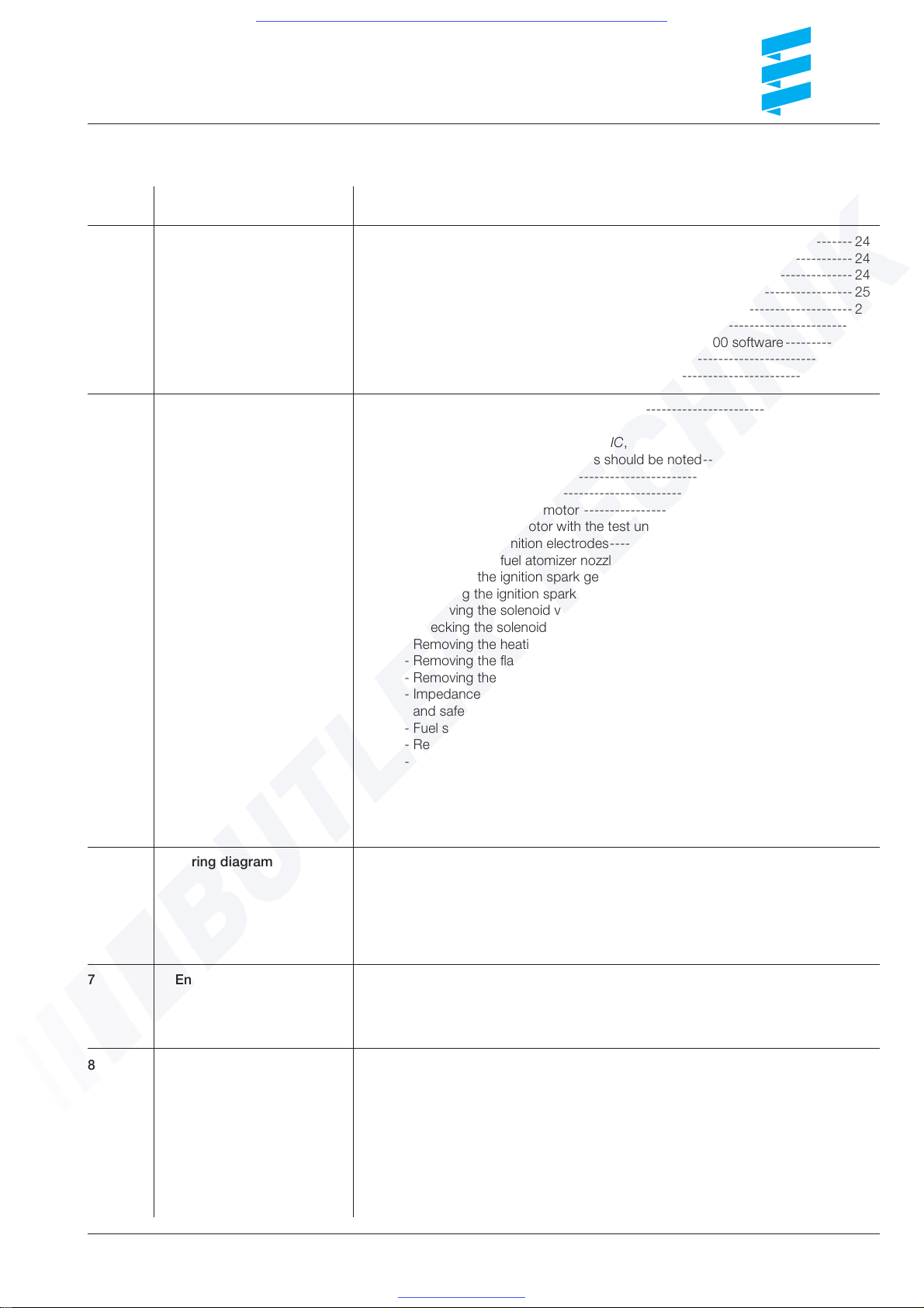
4 Troubleshooting • In the event of faults, start by checking ----------------------------------------- 24
• Control unit locking---------------------------------------------------------------- 24
• Release of control unit when locked --------------------------------------------- 24
• Diagnosis--------------------------------------------------------------------------- 25
• Fault diagnosis - flashing code--------------------------------------------------- 26
• Fault diagnosis with the diagnostic unit ----------------------------------------- 27
• Fault diagnosis with the ISO adapter and the KD 2000 software------------- 28
• Fault diagnosis with the modular timer ------------------------------------------ 29
• Troubleshooting-------------------------------------------------------------- 30 - 33
5 Repair instructions • Assembly drawing------------------------------------------------------------ 34, 35
• Repair instructions
- Prior to working on the HYDRONIC,
the following safety instructions should be noted----------------------------- 36
- Removing the hood-------------------------------------------------------------- 37
- Removing the burner ------------------------------------------------------------ 37
- Removing the burner motor ---------------------------------------------------- 38
- Checking burner motor with the test unit for burner head ------------------- 38
- Removing the ignition electrodes----------------------------------------------- 39
- Removing the fuel atomizer nozzle --------------------------------------------- 39
- Removing the ignition spark generator ---------------------------------------- 40
- Checking the ignition spark generator with the test unit for burner head -- 40
- Removing the solenoid valve --------------------------------------------------- 41
- Checking the solenoid valve with the test unit for burner head ------------- 41
- Removing the heating cartridge for the nozzle holder heater ---------------- 42
- Removing the flame pipe-------------------------------------------------------- 43
- Removing the temperature sensor and safety thermal cutout sensor ------ 44
- Impedances for temperature sensor
and safety thermal cutout sensor ----------------------------------------- 44, 45
- Fuel supply -----------------------------------------------------------------------45
- Removing the fuel strainer ------------------------------------------------------45
- Note regarding fuel quantity ---------------------------------------------------- 45
- Measuring the CO2 content in the exhaust gas ------------------------------- 46
- Adjusting the combustion air --------------------------------------------------- 46
- Taking the water pump apart (standard model)------------------------------- 47
- “Bus 2000” water pump -------------------------------------------------------- 47
6 Wiring diagram • Wiring diagram for the basic heater models ------------------------------- 48, 49
- HYDRONIC 16 - 24 V - 25 2165 01 00 00
- HYDRONIC 24 - 24 V - 25 1817 01 00 00
- HYDRONIC 30 - 24 V - 25 1818 01 00 00
- HYDRONIC 35 - 24 V - 25 1819 01 00 00
• Wiring diagram, control elements------------------------------------------------ 50
7 Environment • Certification------------------------------------------------------------------------- 51
• Test symbol ------------------------------------------------------------------------ 51
• EU declaration of conformity ----------------------------------------------------- 51
• Disposal ----------------------------------------------------------------------------51
8 Service / Index • Regional offices in Germany------------------------------------------------------ 52
• Representative offices abroad----------------------------------------------- 52, 53
• List of Abbreviations--------------------------------------------------------------- 53
• Index A-Z---------------------------------------------------------------------- 54, 55
Troubleshooting and repair instructions
Visit www.butlertechnik.com for more technical information and downloads.
www.butlertechnik.com
4
1 / Introduction
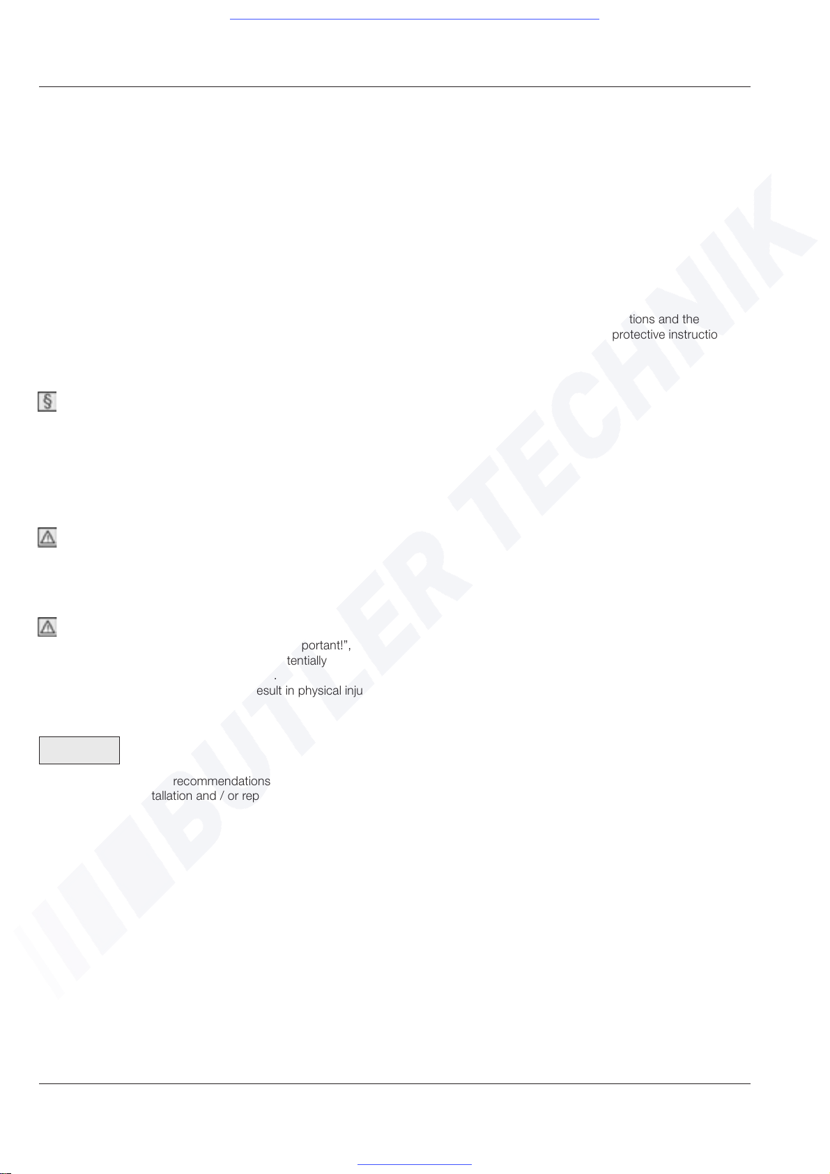
Liability claims / warranty
Adherence to the official regulations and the safety instructions
is essential if any liability claims are to be accepted.
Failure to observe the official regulations and the safety
instructions will result in exemption of the heater manufacturer
from liability.
Accident prevention
The general Accident Prevention Regulations and the
corresponding plant and operational protective instructions
must be observed.
Special notation, pictures and pictograms
This document uses special notation and pictograms to give
emphasis to different types of information.
Their meaning and how you should respond to them are
explained in the examples below.
Special notation and pictures
A bullet symbol (•) is used to indicate a list which is introduced
by a heading.
If an indented dash (-) occurs after a bullet point, then this list
is subordinate to the main bullet list.
Pictograms
Regulation
This pictogram, accompanied by the caption “Regulation”,
indicates a statutory requirement.
Failure to comply with this regulation will cause the
General Type Approval for the HYDRONIC to lapse and
invalidate the warranty and any liability on the part of
J. Eberspächer GmbH & Co.
Danger!
This pictogram, accompanied by the caption ”Danger”, draws
your attention to an imminent danger to life and limb. Failure to
observe this instruction could result in serious injury.
Important!
This pictogram, accompanied by the caption “Important!”,
draws your attention to a situation which is potentially
dangerous to a person and / or the product.
Failure to observe this instruction could result in physical injury
and / or damage to the equipment.
Please note!
This instruction provides recommendations for use and helpful
tips regarding the installation and / or repair of the HYDRONIC.
Visit www.butlertechnik.com for more technical information and downloads.
www.butlertechnik.com
5
1 / Introduction
Important information prior to commencing
work
Applications in which the HYDRONIC may be used
The engine-independent “HYDRONIC 16 / 24 / 30 / 35” water
heaters are intended for installation in the following vehicles
(in each case, the heater output should be appropriate to the
application):
• motor vehicles, especially buses
• building machinery
• trailers
• ships and yachts
Important!
• The heater may only be used and operated for the
applications specified by the manufacturer and in
compliance with the enclosed “Operating Instructions”
for the heater concerned.
• Installation of the HYDRONIC in vehicles that are used to
transport dangerous goods within the provisions of GGVS /
TRS 003, ADR / ADR99 is not permitted.
Intended use of the HYDRONIC
• preheating, de-icing of windows
• heating and maintaining the heated temperature of:
- drivers‘ cabs and work cubicles
- cargo areas
- ships‘ cabins
- travel compartments for passengers and crew
- vehicle engines and assemblies
On the basis of its functional specifications, the HYDRONIC is
not approved for use in the following applications:
• long-term sustained operations, e.g. to pre-heat and heat
- living rooms
- garages
- work enclosures, weekend homes and hunting lodges
- houseboats and similar.
Initial operation of the HYDRONIC and functional testing
following a repair
• Following installation or repair of the HYDRONIC, it is
necessary to carefully bleed the coolant circuit and the entire
fuel supply system. When doing so, the instructions issued
by the vehicle manufacturer must be observed.
• Prior to test running, open all heating circuits (set the
temperature controller to “HOT”).
• During test running of the HYDRONIC, check all water
and fuel connections to ensure that they are leakproof and
securely in position.
• If during operation the HYDRONIC should develop a fault,
then identify the cause of the fault using a diagnostic facility
and rectify.
Content and purpose of this documentation
The Technical Description, Troubleshooting and Repair Manual
is valid for the heaters listed on the front page and contains all
the necessary technical information.
• The Technical Description is contained on pages 4 to 23.
The Technical Description describes the correct installation
of the HYDRONIC in compliance with the relevant
regulations.
• The Troubleshooting and Repair Manual is contained on
pages 24 to 47.
The Troubleshooting and Repair Manual describes the
troubleshooting procedures and the repair work that is
permitted on the HYDRONIC.
Additional documentation on the HYDRONIC
Operating Instructions
The Operating Instructions provide customers with the
information that is necessary for safe handling and use of the
HYDRONIC.
Spare Parts List
The Spare Parts List provides Eberspächer service partners
with the information they need to order spare parts for repair
purposes.
Visit www.butlertechnik.com for more technical information and downloads.
www.butlertechnik.com
6
Statutory requirements
To install the heater in a vehicle subject to the German
regulations governing the registration of motor vehicles
(StVZO), a “General Type Approval” has to be issued by the
Federal Motor Vehicle Office (Kraftfahrtbundesamt) and the
appropriate official test symbol must be indicated on the
heater rating plate.
HYDRONIC 16 S 329
HYDRONIC 24 S 297
HYDRONIC 30 S 295
HYDRONIC 35 S 296
The statutory requirements are binding for applications which
fall within the scope of the StVZO (regulations governing the
registration of motor vehicles) and should also be adhered to
in countries in which there are no specific regulations.
Where heaters are installed in vehicles that are not subject
to the StVZO (e.g. ships) the directions and installation
instructions which apply specifically to those cases must be
observed.
Directions regarding installation and repair
• Installation of heaters must comply with the Installation
Instructions. In the following cases,
a) vehicle type test under §20 StVZO
b) individual test under §21 StVZO or
c) examination under §19 StVZO,
the heater must be checked by an officially certified
expert or tester of motor vehicles, a motor vehicle
expert or employee in accordance with Section 7.4 a of
the Annex to the StVZO,
and in case c) this must be certified with details of the
vehicle manufacturer, vehicle type and vehicle identification
number on the Final Approval Certificate contained in the
copy of the General Type Approval.
The validity of the Type Approval depends on this.
The Final Approval Certificate must be kept in the vehicle.
• Where the heater is installed in a special-purpose vehicle
(e.g. a vehicle for transporting hazardous goods), the
installation must comply with the regulations
applicable to such vehicles.
• Installation in the driver‘s cab or passenger compartment
of buses containing more than eight seats in addition to the
driver‘s seat is not permitted.
• The instruction sticker, “Switch off heater before filling up”
contained in the Scope of Supply for the heater, must be
displayed in a prominent position in the vehicle (near to the
fuel filler connection).
Directions for operation
• The heater must be switched off during refuelling.
• Operation of the heater in an enclosed space is
not permitted, e.g.
- garages
- underground car parks
- multi-storey car parks
Please note!
• All other installation requirements related to the General
Type Approval are printed in the relevant sections of these
Installation Instructions.
• The Final Approval Certificate is contained in the Operating
Instructions.
1 / Introduction
Visit www.butlertechnik.com for more technical information and downloads.
www.butlertechnik.com
7
1 / Introduction
Emergency cutout -
emergency circuit breaker
If an emergency cutout - emergency circuit breaker should be necessary during operation, the following
procedure should be followed:
• switch off HYDRONIC on the control element
or
• take out the fuse
or
• open the battery isolating switch
or
• disconnect the HYDRONIC from the battery
Safety instructions for operation
Important!
• Operation of the heater is not permitted where flammable
vapours or dust could build up, for example in the vicinity of
- fuel depots
- coal stores
- timber stores
- stores of grain and similar.
• The delayed shutoff of the HYDRONIC must not be
terminated prematurely, e.g. through activation of the
battery isolating switch, except in case of emergency
cutout.
Safety instructions for installation and
repair of the HYDRONIC
Danger of injury, fire and poisoning!
• Disconnect the vehicle battery prior to starting work.
• Prior to starting any repair work, switch off the HYDRONIC
and allow all hot components to cool down.
Important!
• The heater may only be installed or, in the case of repair
or work under guarantee, repaired by an Eberspächer
service partner authorised by the manufacturer and
in accordance with the directions contained in this
documentation or any special installation suggestions.
• Repairs by non-authorised third parties and / or
using non-genuine spare parts are dangerous and are
therefore not permitted. They will result, moreover, in lapse
of the General Type Approval of the heater and, in the case
of motor vehicles, possibly of the General Operating Permit
for the vehicle as well.
• The following measures are not permitted:
- modification of heater-relevant components,
- use of non-original parts which have not been approved
by the Eberspächer company,
- departures from legal, safety and / or function-relevant
directions contained in the Installation Instructions and
the Operating Instructions, either in the installation or
operation of the heater.
This applies in particular to the electrical wiring (wiring
diagrams), the fuel supply, the combustion air and
exhaust gas piping.
• Only original accessories and spare parts may be used
during installation or repair.
• The HYDRONIC may only be operated using control
elements approved by the Eberspächer company.
Use of other control elements can lead to malfunctioning of
the heater / heating operation.
• Prior to reinstalling a heater in a different vehicle, the
water-carrying parts of the heater must be rinsed with
clear water.
Visit www.butlertechnik.com for more technical information and downloads.
www.butlertechnik.com
8
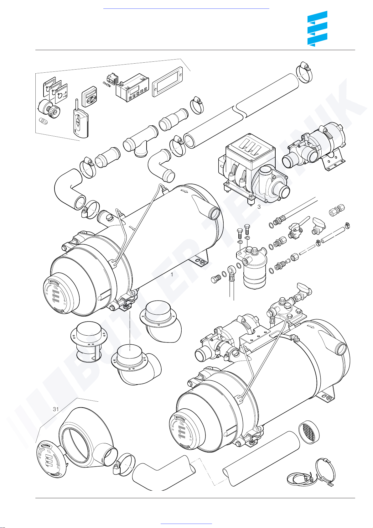
Cat. No. HYDRONIC and additional
equipment
Fig. No. / Designation
Cat. No.
1 HYDRONIC 16 - 24 V 25 2165 02 00 00
1 HYDRONIC 24 - 24 V 25 1817 02 00 00
2 HYDRONIC 24 - 24 V 25 1817 05 00 00
Compact model
1 HYDRONIC 30 - 24 V 25 1818 02 00 00
2 HYDRONIC 30 - 24 V 25 1818 05 00 00
Compact model
1 HYDRONIC 35 - 24 V 25 1819 02 00 00
2 HYDRONIC 35 - 24 V 25 2041 05 00 00
Compact model
Additional equipment which has to be ordered separately
3 “Bus 2000” water pump 25 1818 25 00 00
4 Water pump, 5000 I/h 25 1578 25 00 00
5 Hose clip, dia. 40 mm - 47 mm 152 00 158
6 Hose bend 38 mm dia. 360 00 300
7 Connecting pipe 38 mm dia. 25 1214 89 00 21
8 T-piece 38-38-38 mm dia. 25 1371 89 04 00
9 Reducing piece, 38/28 mm dia. 25 1214 89 00 19
10 Hose clip, dia. 32mm - 39 mm 152 61 097
11 Pipe bend, 38 mm dia. 25 1214 89 00 03
12 Water hose 38 mm dia. 360 75 096
13 Exhaust pipe connection
70 mm dia. 25 2025 89 01 00
14 Exhaust pipe connection
70 mm dia. 22 1000 40 04 00
15 Exhaust pipe bend 70 mm dia. 22 1000 40 03 00
16 Fuel filter 330 00 052
17 Hollow screw, M 14 x 15 104 10 040
18 Seal ring, A 14 x 18 323 16 006
19 Fuel intake pipe 25 1698 05 03 00
20 Screw coupling, M14 x 1,5 266 42 004
21 Spherical bush 263 35 080
22 Cap nut, M 14 x 15 116 10 040
23 Fuel pipe dia. 6 x 1 mm (copper),
per metre 080 16 003
24 Fuel hose dia. 5 x 3 mm 360 75 350
25 Hose clip 11 mm dia. 10 2063 01 10 98
26 Screw coupling, M 14 x 1.5 25 1706 05 01 00
27 Ball valve, M 14 x 1.5 330 00 019
28 Fuel return line 25 1698 05 04 00
29 Valve 330 00 210
30 Reducing joint 8/6 mm 266 00 026
31 Hood with hose connection 22 1000 40 06 00
32 1 m flexible hose, 60 mm dia. 10 2114 31 00 00
33 Hose clip 10 2064 05 00 70
34 Air hose fastening set 22 1000 50 02 00
35 Grille plastic 25 1688 80 06 00
2 / Product Information
Cat. No. Control element, optional
Quantity / Designation Cat. No.
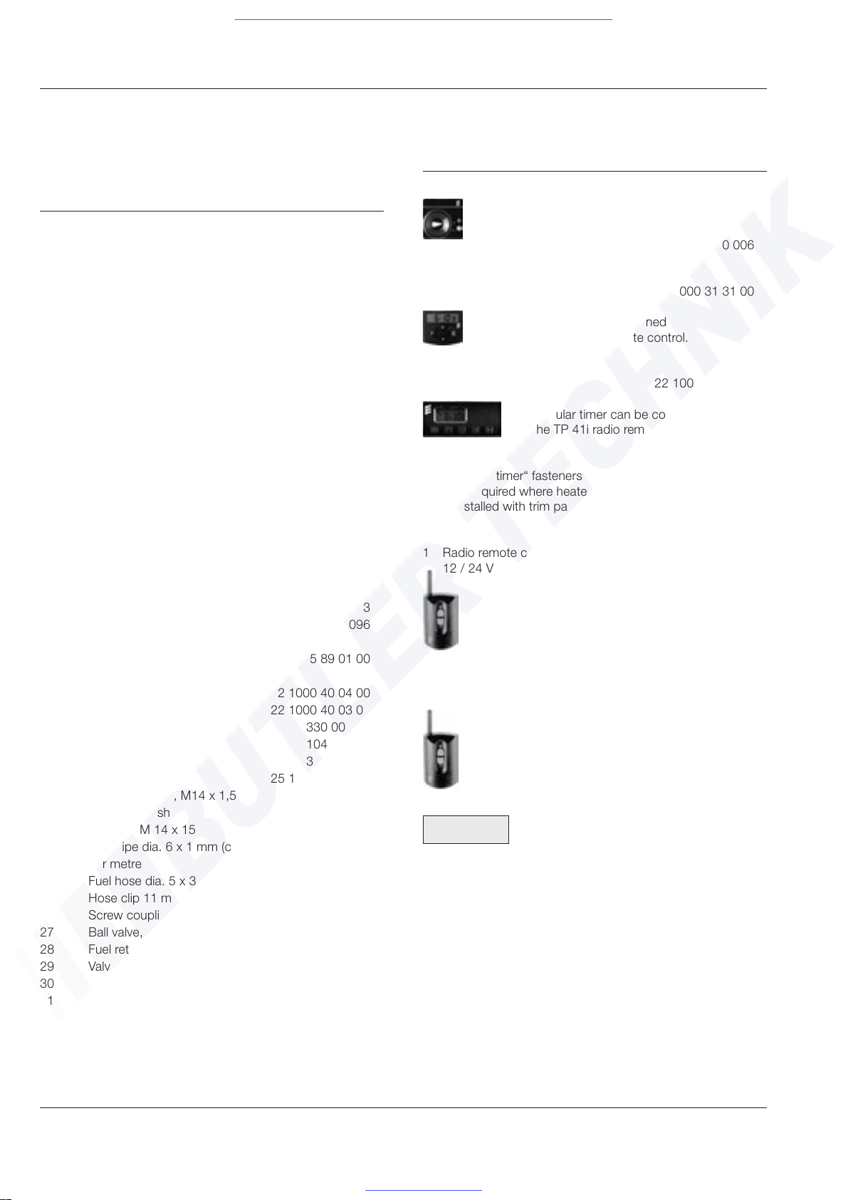
1 Universal switch 25 1380 89 04 00
ON / OFF switch
Additionally required:
1 electric bulb 207 00 006
1 Mini-timer 12 / 24 V 22 1000 31 31 00
The mini-timer can be combined
with the TP 41i radio remote control.
1 Modular timer -12 / 24 V 22 1000 30 34 00
The modular timer can be combined
with the TP 41i radio remote control.
1 „Modular timer“ fasteners 25 1482 70 01 00
Only required where heater
is installed with trim panel
1 Radio remote control TP 4i 22 1000 30 99 00
12 / 24 V
The TP 4i radio remote control can only be used
in combination with the modular timer.
1 Radio remote control TP 41i 22 1000 31 39 00
12 / 24 V
The TP 41i radio remote control can be used
both independently and also in combination
with the mini-timer.
(Cat. No. of the mini-timer - 22 1000 31 31 00)
Please note!
Choice of control elements must be appropriate to
the purpose for which the HYDRONIC is to be used.
Selection criteria:
• switching on / off
• program preselection and / or remote control
Operating Instructions are enclosed with the control
elements. These are intended for the customer along
with the Operating Instructions for the HYDRONIC.
For other additional equipment, see Additional Equipment
Catalogue.
Visit www.butlertechnik.com for more technical information and downloads.
www.butlertechnik.com
9
2 / Product Information
Drawing 1
1
4
5
7
5
6
9
14
24
23
22
21
20
16
26
27
28
18
18
19
17
5
2
3
11
8
10
12
13
15
25
18
29
30
31
5
Control elements
32
35
34
33
18
25
5
Visit www.butlertechnik.com for more technical information and downloads.
www.butlertechnik.com
10
Options
• When the “Lower Temperature” option is selected, the
adjustable “ON / OFF” temperatures drop by approx. 8K.
For information regarding the “ON / OFF” switch for
reducing the temperature, see the wiring diagrams on
pages 48 to 50.
• The water pump can also be operated independently
of the HYDRONIC if controlled appropriately.
For information regarding the additional “ON / OFF” switch
for separate control of the water pump, see the wiring
diagrams on pages 48 to 50.
• The vehicle blower is controlled by being switched on and
off at the following temperatures.
- Water temperature >55°C --> vehicle blower “ON”
- Water temperature <50°C --> vehicle blower “OFF”
For further information on control of the vehicle blower, see
wiring diagrams on pages 48 to 50.
Switching off the HYDRONIC
Once the HYDRONIC has been switched off, the fuel solenoid
valve closes and at the same moment the 3-minute delayed
shutoff commences.
Following termination of the delayed shutoff, the HYDRONIC is
automatically switched off.
Please note!
• The fuel continues to circulate until the heater is switched
off, including during the delayed shutoff period.
Function description
Switching on the HYDRONIC
When the HYDRONIC is switched on, a component test
lasting 3 seconds is carried out, following which the water
pump is started up.
Note:
If the water temperature is <5°C, the nozzle holder heater
is switched on for 60 seconds, during which start-up of the
burner is deferred.
Burner start-up
The electric motor starts up and drives the combustion air
blower impeller and the fuel pump.
After approx. 10 seconds the ignition is switched on, following
which the fuel solenoid valve opens.
Within this 10 second period a rotary check of the electric
motor is performed.
In the combustion chamber the combination of fuel and combustion air forms a combustible mixture.
The mixture is ignited by a high-voltage ignition spark.
The flame monitor detects the flicker frequency of the flame
and switches off the ignition spark generator.
The hot flammable gases flow through the heat exchanger and
conduct the heat to the heating medium.
Please note!
• The heater works as a function of the heat requirement.
Hence switching on and off times of the burner are of
different lengths.
• The water pump continues to operate the whole time that
the heater is on, as well as in the controlled intervals and
during the delayed shutoff.
Construction of the HYDRONIC
The HYDRONIC consists of a heat exchanger and a
removable burner.
The heat exchanger is a combustion chamber, consisting of a
flame pipe with integrated mixer.
If required, the flame pipe can be removed from the heat
exchanger.
The control unit and electric motor are attached under the
burner hood on the burner flange.
The fuel pump forms an integral part of the burner casing.
To operate the HYDRONIC, the following additional equipment
is required:
• water pump
• parts for connecting to the water circulation system
• additional equipment for the fuel supply
• additional equipment for the exhaust gas piping
• control element
For catalogue numbers of the additional equipment, see
pages 8 and 9.
For other additional equipment, see Additional Equipment
Catalogue.
2 / Product Information
Special features of the HYDRONIC
• If the water flow rate is insufficient, the water outlet
temperature is limited by early correction.
• The temperature rise of the heating medium is monitored
by time.
If the temperature rises too quickly (because the water flow
rate is insufficient), the heater will automatically switch itself
off and the delayed shutoff will commence, following which
the cycle starts up again.
• The values of the temperature sensor and the safety
thermal cutout sensor are continuously compared, resulting
in improved safety since, if the difference in the values is
too great (because the water flow rate is insufficient), a fault
shutdown will occur.
Visit www.butlertechnik.com for more technical information and downloads.
www.butlertechnik.com

11
Sectional view
1 Hood (CO2 setting)
2 Coupling
3 Control unit
4 Ignition spark generator
5 Flame monitor
6 Solenoid valve
7 Temperature sensor
8 Ignition electrodes
9 Combustion chamber
10 Safety thermal cutout sensor
11 Relay (vehicle blower control)
A Exhaust gases
B Fuel
V Combustion air
WA Water outlet
WE Water inlet
12 Fuses
13 Modular timer
14 Fan wheel
15 Electric motor
16 Fuel connection
17 Nozzle holder heater
18 Fuel atomizer nozzle
19 Flame pipe
20 Heat exchanger
21 “Bus 2000” water pump
22 Exhaust pipe connection
2 / Product Information
Drawing 2
Visit www.butlertechnik.com for more technical information and downloads.
www.butlertechnik.com
12
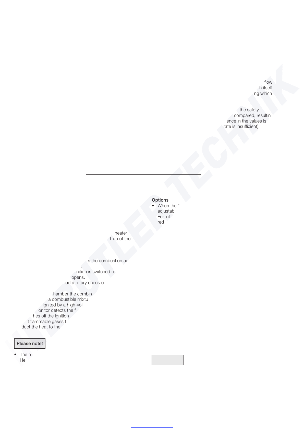
Control diagram
Functional diagram
2 / Product Information
Drawing 3
Nozzle holder heater
(On at temp. < 5 °C)
Water pump
Solenoid valve
Ignition spark
generator
Electric Motor
From control unit 25 1818 53 00 00,
switching on and off the nozzle holder
heater is temperature-controlled
Operation
HYDRONIC
OFF
Delayed shutoff
HYDRONIC
ON
Sec.
3
10
10
60
180
Component test
From control unit 25 1818 53 00 00
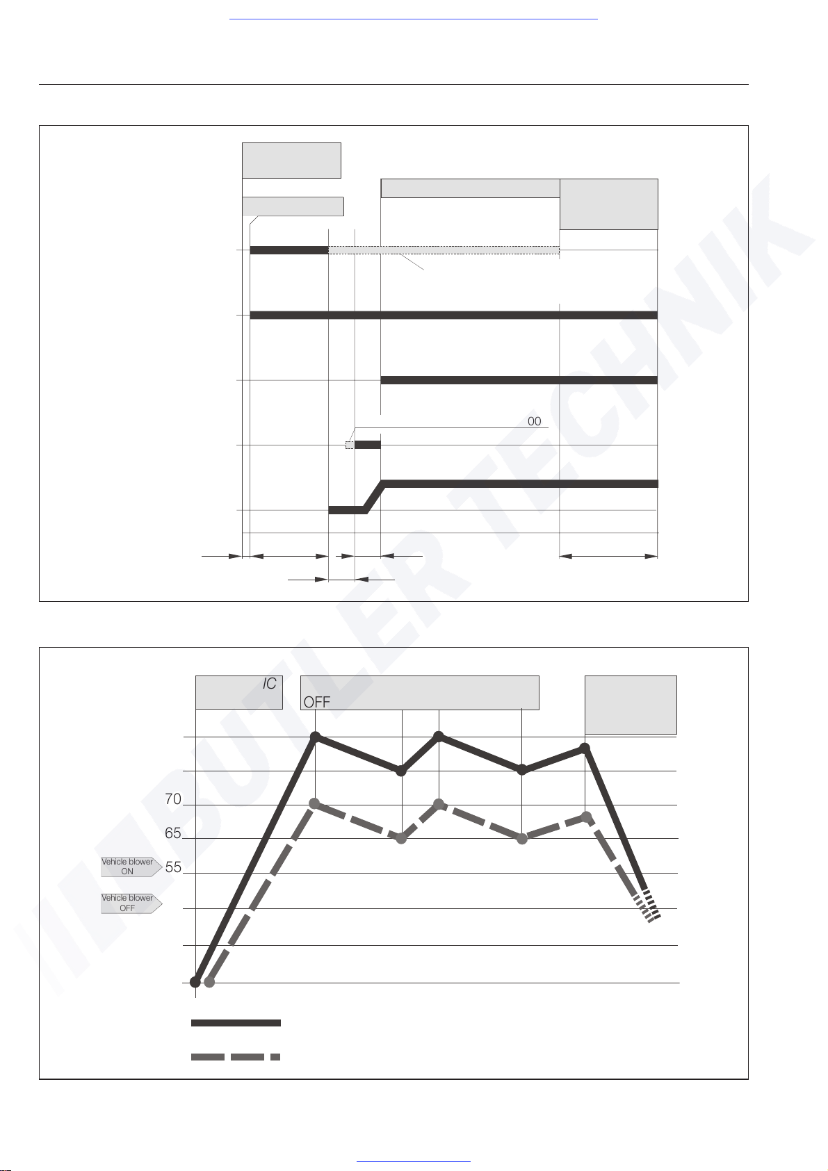
Drawing 4
HYDRONIC
ON
OFF ON
OFF ON
Normal operation
Hydronic
OFF
delayed shutdown
3 min.
Regulation - normal
Regulation when "Lower Temperature" selected
Vehicle blower
ON
Vehicle blower
OFF
t °C
78
73
70
65
55
50
5
0
Visit www.butlertechnik.com for more technical information and downloads.
www.butlertechnik.com
13
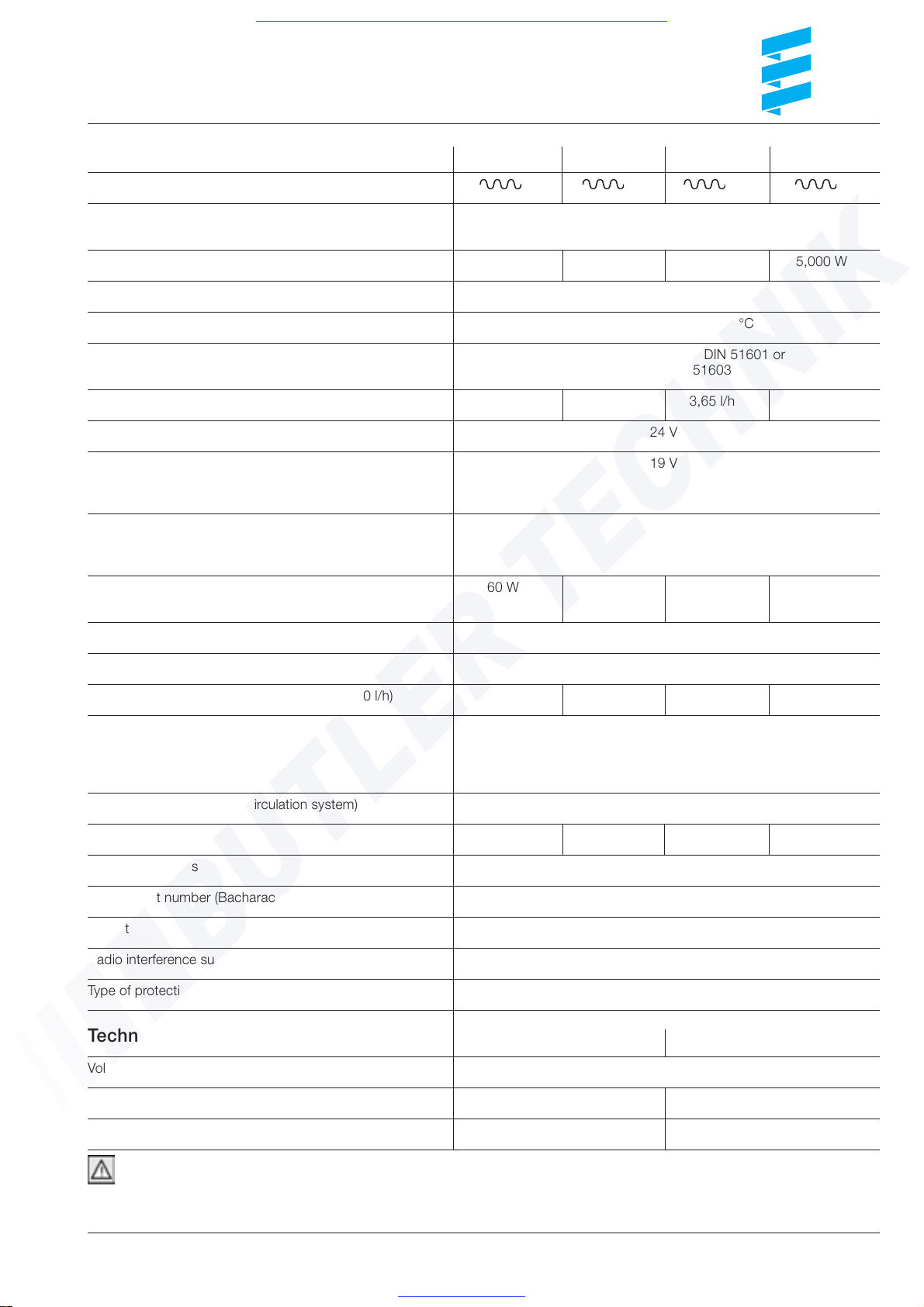
Technical Data HYDRONIC 16 HYDRONIC 24 HYDRONIC 30 HYDRONIC 35
Test symbol S 329 S 297 S 295 S 296
Heating medium Mixture of water and refrigerant
(Max 50% proportion of refrigerant
Heating capacity (at ambient temperature of 20ºC) 16,000 W 24,000 W 30,000 W 35,000 W
Temperature control values - at water inlet ON 73 °C / OFF 78 °C
Temperature control values - at water outlet ON 85 °C / OFF 118 °C
Fuel Commercial grade diesel - DIN 51601 or
fuel oil EL - DIN 51603
Fuel consumption (at ambient temperature of -10ºC) 2.0 l/h 2.9 l/h 3,65 l/h 4,2 l/h
Rated voltage 24 V
Lower voltage limit 19 V
The control unit is protected against undervoltage so that when the
voltage drops to the predefined limit, the HYDRONIC is switched off.
Upper voltage limit 30 V
The control unit is protected against overvoltage so that when
the voltage limit is exceeded, the HYDRONIC is switched off .
Electric power consumption 60 W 80 W 105 W 120 W
(during combustion / without circulating pump)
Water content of heat exchanger Approx. 2 l
Water content of water circulation system Min. 10 l
Minimum throughput of heating medium (± 200 l/h) 1,400 l/h 2,000 l/h 2,600 l/h 3,000 l/h
Permissible ambient temperature In operation: -40°C to +85°C
During transportation / in storage: -40ºC to + 100ºC
For combustion air: <60°C
Supply medium: -40°C to +90°C / for a short time up to +120°C
Operating pressure (water circulation system) < 2,5 bar
CO2 - value 9 -11 vol. % 9 -11 vol. % 9 -11 vol. % 9.5 -11.5 vol. %
CO in exhaust gas
<
0,04 vol. %
Smoke spot number (Bacharach scale)
<
4
Weight Approx. 18 kg
Radio interference suppression level UKW 4 / KW 3 / MW 5 / LW 3
Type of protection IP 64
Technical Data - Water Pump Water pump standard Bus 2000 water pump
Voltage (±20%) 24 V
Power consumption 110 W 250 W
Capacity / at delivery pressure 5,000 I/h - 200 mbar 6000 l/h - 500 mbar
2 / Product-Information
All technical data ±10 %; where deviation applies, the
deviation values are specified.
Important!
The specified technical data must be adhered to, otherwise it is
possible for the HYDRONIC to malfunction.
Visit www.butlertechnik.com for more technical information and downloads.
www.butlertechnik.com
14
2 / Product Information
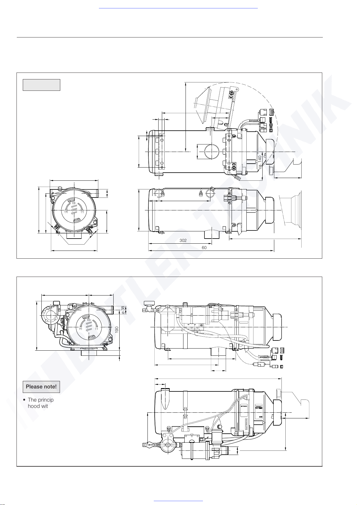
Principal dimensions
HYDRONIC - compact model
HYDRONIC - standard model
Drawing 5
Drawing 6
ø 38
(+) (- )
2
224
115
190
ø70
320
302
233
24
ø 38
180
130 min.
50
600
153
Please note!
• If there is enough space, the burner can be
swung out for routine checks - see drawing.
• The principal dimensions are the same when a
hood with hose connection is mounted.
29
M8
150
ca. 335
70
130 min.
302
Min. 375 mm for dismantling
Flame pipe
220
110
222
190
ø 38
ø 220
244
600
2
230
82
320
M10 x1
ca. 140
50
Please note!
• The principal dimensions are the same when a
hood with hose connection is mounted.
Visit www.butlertechnik.com for more technical information and downloads.
www.butlertechnik.com
15
Regulation!
• Installation in the driver‘s cab or passenger compartment
of buses containing more than eight seats in addition to the
driver‘s seat is not permitted.
Please note!
• Mount the HYDRONIC below the minimum cooling water
level (expansion tank, radiator, vehicle heat exchanger).
• Further information on installation (e.g. for boats and ships)
is available from the manufacturer on request.
• For installation of the HYDRONIC in a case, see page 16.
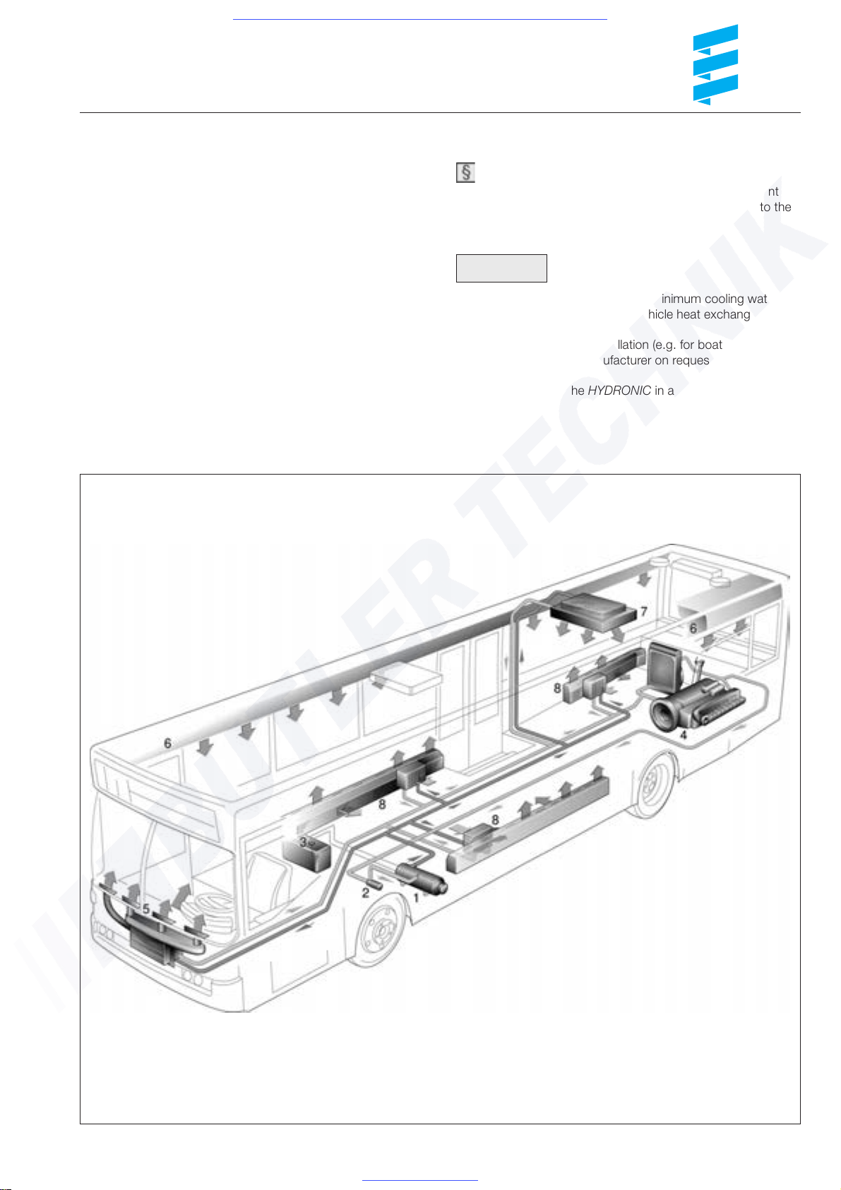
3 / Installation
1 HYDRONIC
2 Water pump
3 Tank connection
4 Vehicle engine
5 Front heater
6 Roof air ducts
7 Roof heater
8 Floor heater
Drawing 7
Installation position
The heater should be installed as low down as possible in
the vehicle, e.g. in the engine compartment or in a stowage
area.
This will ensure that the heater and water pump are
automatically ventilated.
Other installation positions are also permitted as long as
they comply with the installation requirements stated in these
Installation Instructions.
When choosing where to install the heater, care must be taken
to ensure that there is sufficient space to disassemble the
hood (130 mm) and the flame pipe (375 mm).
All openings towards the outside must be splash-proof.
Example of a HYDRONIC installation in a bus
Visit www.butlertechnik.com for more technical information and downloads.
www.butlertechnik.com
16
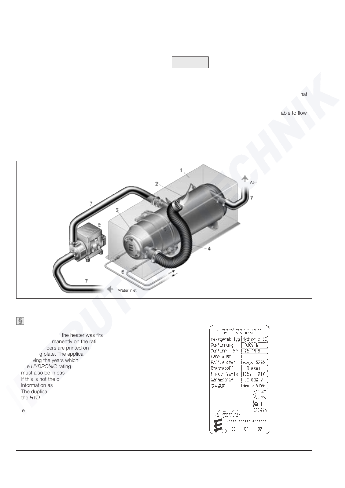
Rating plate
Regulation!
• The year in which the heater was first commissioned must
be shown permanently on the rating plate. For this purpose
3 year numbers are printed on the appropriate area of
the rating plate. The applicable year must be indicated by
removing the years which are not applicable.
• The HYDRONIC rating plate is attached to the burner and
must also be in easy view in the installed condition.
If this is not the case, a duplicate containing the same
information as the original rating plate can be attached.
The duplicate must be attached in a prominent position on
the HYDRONIC or on a cover in front of the HYDRONIC.
The duplicate is affixed to the hood in a manner which enables
it to be taken off.
Please note!
• The case must be sufficiently ventilated from outside that
the permitted ambient temperature is not exceeded.
• Air vents must be arranged on the case in such a way that
they cannot become clogged up with dirt or snow.
• Any water which penetrates the case must be able to flow
out.
Installation of the HYDRONIC in a case
If installation in the engine compartment or stowage
compartment of the vehicle is not possible, than the
HYDRONIC can also be installed in a case.
The case containing the installed HYDRONIC is then affixed
to the vehicle at a suitable location, e.g. to the longitudinal
chassis frame.
It is recommended that a hood with a hose connection is
mounted for the combustion air intake. The combustion air is
then drawn in outside of the case via a flexible hose.
In this way it is possible for the combustion air to be drawn
from an area where the temperature is within the permitted
range and protection is provided against dirt accumulation.
Place a protective grille on the flexible hose.
1 Case
2 HYDRONIC
3 Hood with hose connection
4 Flexible hose with
protective grille
5 Water pump
6 Fuel lines
7 Water hose
Example of a HYDRONIC installation in a case
3 / Installation
Drawing 9
Drawing 8
Water inlet
Fuel
Water outlet
Heater type
Model
Model no.
Factory no.
Test symbol
Fuel
Electrical rating
Heating capacity
Operating gauge pressure
Not to be installed in
driver‘s cab or
passenger compartment
Data first used
Visit www.butlertechnik.com for more technical information and downloads.
www.butlertechnik.com
17
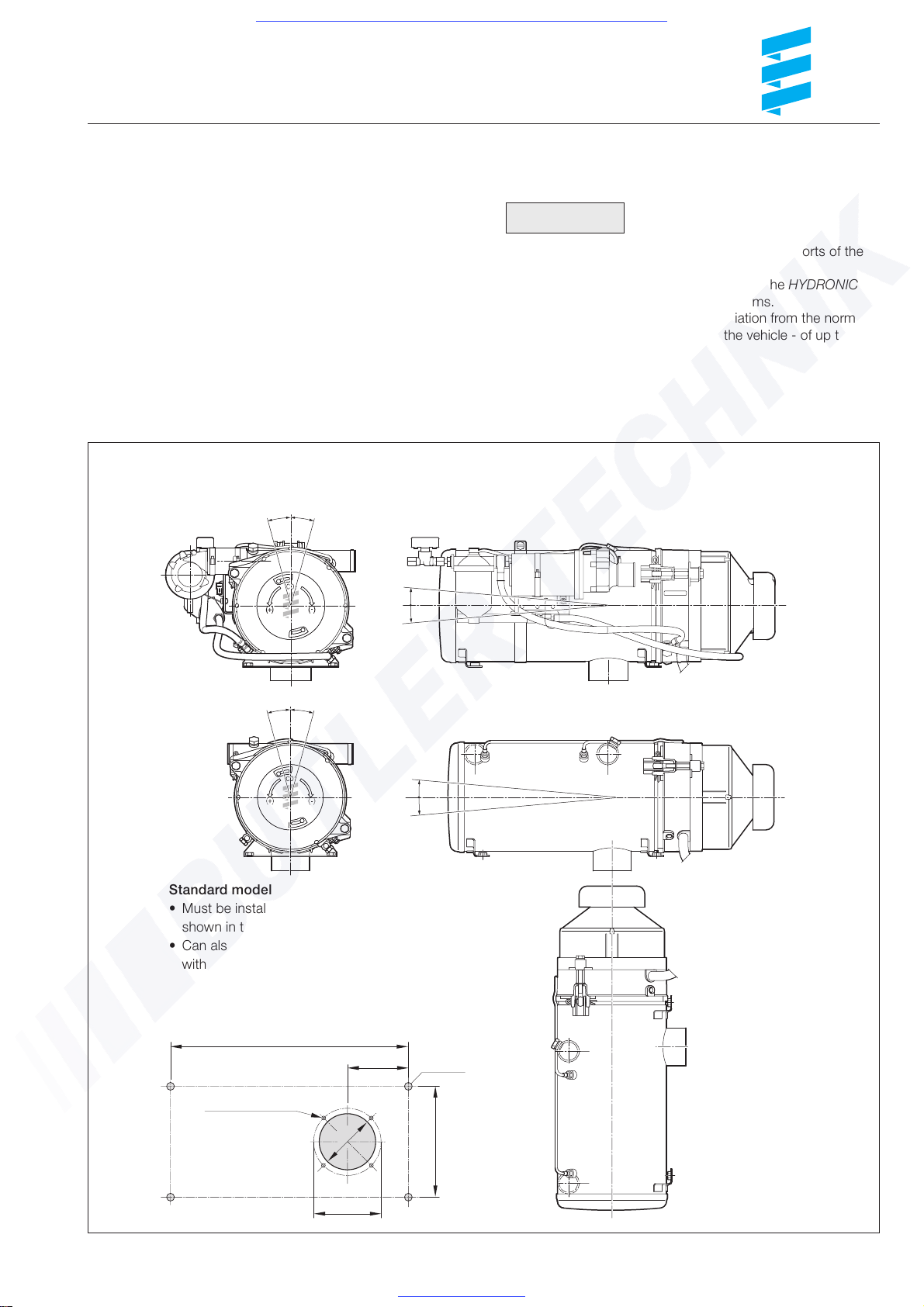
3 / Installation
Permissible installation positions and
attachment of the HYDRONC
The HYDRONIC should if possible be installed in the normal
position.
To do this, transfer the 4 fastening holes and the through-hole
for the exhaust outlet - as shown in the diagram - to the
mounting surface and drill.
Fasten the HYDRONIC to the vehicle with the two mounting
supports.
Permissible installation positions and template for holes for the
HYDRONIC - standard model and compact model
Please note!
• The support surface for the two mounting supports of the
HYDRONIC must be flat.
• Depending on the installation conditions, the HYDRONIC
can be inclined, as shown in the diagrams.
During operation of the heater a deviation from the normal
position - caused by the incline of the vehicle - of up to +15º
in all directions is possible.
Compact model - must be installed in level position with the
deviations shown in the diagram.
Drawing 10
15°
15
°
5°
5°
15°
15°
5°
5°
320
82
Ø 9 (4x)
Ø4,5 at M4
Ø2,9 at B3,9
150
82
75
Hole template for the HYDRONIC - standard model
and compact model
Standard model
• Must be installed in level position with the deviations
shown in the diagram
• Can also be installed in vertical installation position
without any deviations.
Visit www.butlertechnik.com for more technical information and downloads.
www.butlertechnik.com
 Loading...