

Page 1

OPERATING INSTRUCTIONS
QUICK START GUIDE
INSTALLATION INSTRUCTIONS
A WORLD OF COMFORT
EN
INSTALLATION INSTRUCTIONS
EASYSTART SELECT
VEHICLE HEATERS | TECHNICAL DOCUMENTATION
CONTROL UNIT FOR
EBERSPÄCHER PARKING HEATERS
Page 2

2 | VEHICLE HEATERS – TECHNICAL DOCUMENTATION
CONTENTS
CHAPTER CHAPTER TITLE PAGE
CHAPTER CONTENTS
1 INTRODUCTION
Please read first 4
Safety instructions 4
Intended use 4
General information 4
– VENTILATION operating mode 4
– Temperature sensor 4
– Installation instructions for special functions 4
Technical data 5
Scope of supply 5
Sketch of EasyStart Select scope of supply 6
2 INSTALLATION
Installing the EasyStart Select 7
Installing the tab connector of the EasyStart Select lead harness 7
EasyStart Select installation sketch 8
Connector housing (Chamber assignment seen from the cable inlet side) 8
-XS4 / -XB4 connector assignment table 9
Installation sketch key 9
Connection of bush housing to the control unit lead harness 9
Page 3

VEHICLE HEATERS – TECHNICAL DOCUMENTATION | 3
CONTENTS
3 STARTUP / CONFIGURATION
Initial startup 10
Configuring the EasyStart Select 10
Opening the vehicle workshop menu 10
Selecting the settings for the standard configuration 11
– Selecting the temperature units – Item 2: 11
– Changing the preset operating time – Item 4: 11
– Resetting to as-delivered condition – Item 5: 12
– Functional check 12
4 WHAT TO DO IF …?
Possible displays in the event of a fault 13
5 CIRCUIT DIAGRAM
– EasyStart Select connection to Hydronic, Hydronic II, Hydronic II C, Hydronic
II Comfort, Hydronic M II 15
– EasyStart Select connection to Airtronic, Airtronic M, Airtronic L 16
6 SERVICE
EC Declaration of Conformity 17
Hotline 17
Page 4

4 | VEHICLE HEATERS – TECHNICAL DOCUMENTATION
PLEASE READ FIRST
Before you start to install the EasyStart Select,
always read through these installation instructions carefully.
These installation instructions contain important information, which you need to install the
EasyStart Select.
SAFETY INSTRUCTIONS
DANGER!
Always note and follow all information and
notes, especially the safety instructions in
this document and in the heater's technical
description!
INTENDED USE
The EasyStart Select is used to select the
operating mode, to set the operating time, and
to switch On / Off the heater installed in the
vehicle.
PLEASE NOTE!
Improper use and use outside the specified
purpose cancels all liability and warranty.
1 INTRODUCTION
GENERAL INFORMATION
VENTILATION OPERATING MODE
In VENTILATION mode the fan of water heaters is actuated by directly bypassing heating
mode. If the symbol is not displayed the
VENTILATION function is not available for the
heater.
If you have any further questions about
VENTILATION mode, please dial the service
telephone number see page 17.
TEMPERATURE SENSOR
The temperature sensor that is installed in
the heater and which controls the temperature inside the vehicle is also used for the
EasyStart Select temperature display.
INSTALLATION INSTRUCTIONS FOR SPECIAL
FUNCTIONS
These installation instructions describe
the standard configuration. For details of
enhanced configuration of the EasyStart
Select and for special functions such as combinations with various EasyStart control units,
installation in ADR vehicles, operating the
heater and additional unit, etc. the “Special
Functions and Diagnosis” installation instructions are available to view and to download
from www.eberspaecher-standheizung.com/
download.
Page 5

VEHICLE HEATERS – TECHNICAL DOCUMENTATION | 5
TECHNICAL DATA
Operating voltage 12 volt / 24 volt
Dimensions W: 55 mm, H: 46 mm, D: 9 mm
allowable ambient temperature – 40 °C to +85 °C
LCD ambient temperature The display becomes sluggish in tem-
peratures below –10 °C, i.e. the flashing
sequence of the symbols is somewhat
slower, the contrast becomes weaker above
+70 °C.
ORDER NO.
EasyStart Select 12 / 24 volt 22 1000 34 13 00
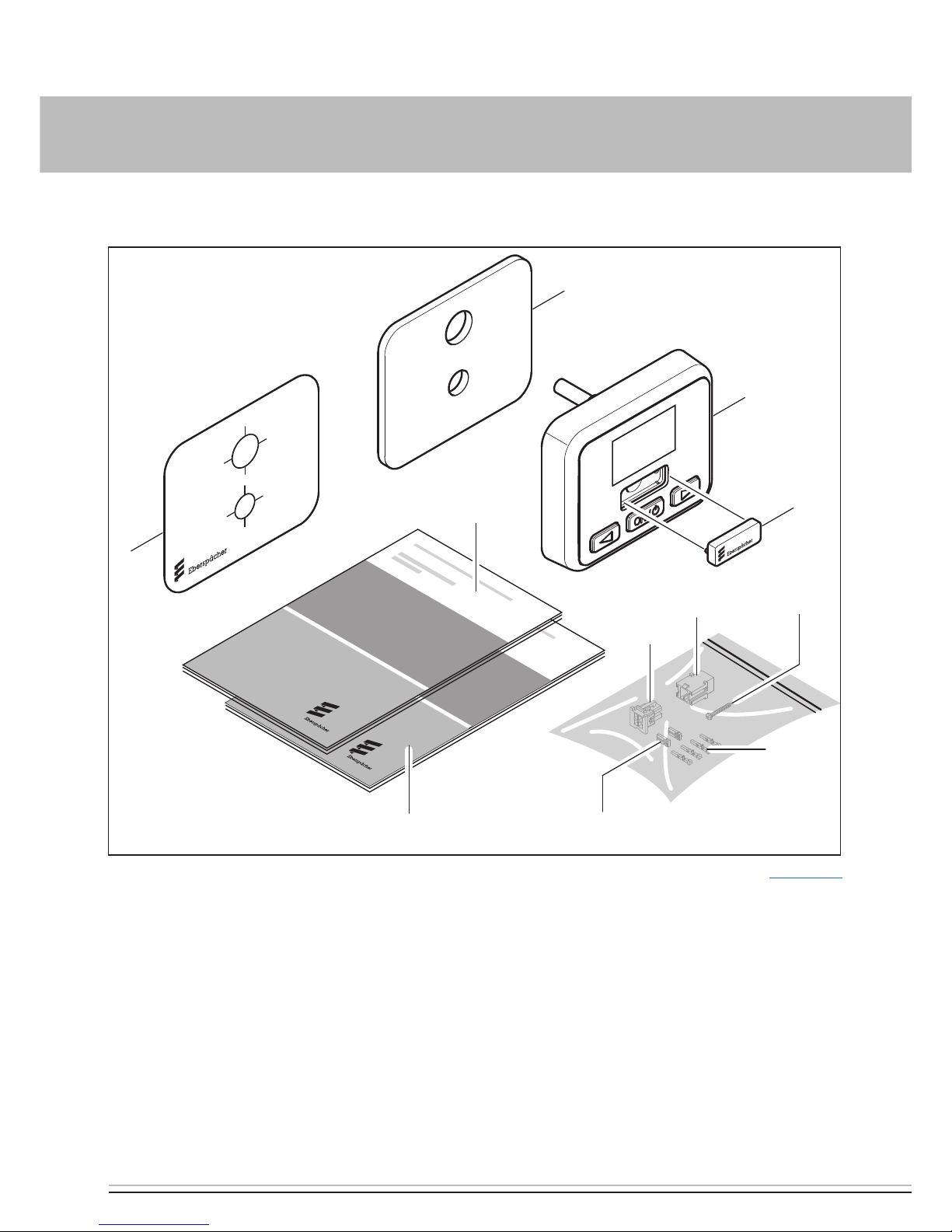
SCOPE OF SUPPLY
Sketch see page 6.
No. in sketch Quantity Designation
1 1 EasyStart Select 12 / 24 volt
2 1 Cover
3 1 Foam underlay
4 1 Connector housing, 4-pin (in the bag)
5 1 Bush housing, 4-pin (in the bag)
6 2 Contact locking devices (in the bag)
7 4 Contacts (in the bag)
8 1 Self-tapping screws (in the bag)
9 1 Template
10 1 Installation instructions
11 1 Operating instructions
1 INTRODUCTION
Page 6
6 | VEHICLE HEATERS – TECHNICAL DOCUMENTATION
SKETCH OF EASYSTART SELECT SCOPE OF SUPPLY
1
2
85
7
6
4
11
10
9
3
Key see page 5
1 INTRODUCTION
Page 7

VEHICLE HEATERS – TECHNICAL DOCUMENTATION | 7
2 INSTALLATION
INSTALLING THE EASYSTART SELECT
CAUTION!
When drilling the fixing and connection holes
in the dashboard, concealed components
behind it could be damaged.
Î Check that the space behind the installa-
tion area is free from components.
Install the EasyStart Select in a suitable place
on the dashboard, within the driver's view and
connect as shown in the sketch on page 8
and the circuit diagram from page 15.
Use the template supplied to position and
drill the two holes ø 6.5 mm and ø 9 mm.
The foam underlay can be used if neces-
sary to level out unevenness. To do this,
pull off the protective film and stick the
foam underlay onto the installation area.
Then pull off the second protective film.
Feed the lead harness from the EasyStart
Select through the drillhole ø 9 mm.
Insert the EasyStart Select with expansion
plug into the drillhole ø 6.5 mm.
Screw the fixing screw into the expansion
plug and therefore fasten the EasyStart
Select.
INSTALLING THE TAB CONNECTOR OF THE
EASYSTART SELECT LEAD HARNESS
Plug the tab connector of the EasyStart
Select lead harness into the 4-pin connector housing (for details of connector
housing pin assignment see page 8 and
page 9).
Push the contact locking device into the
connector housing.
PLEASE NOTE!
When installing the connector, ensure that the
locking tangs always face the middle of the
connector. Only in this position do the tangs
latch into the housing (see sketch above).
Page 8

8 | VEHICLE HEATERS – TECHNICAL DOCUMENTATION
2 INSTALLATION
EASYSTART SELECT INSTALLATION SKETCH
Key see page 9
CONNECTOR HOUSING (Chamber assignment seen from the cable inlet side)
-XS4 (Item 4) -XB4 (Item 5)
Page 9

VEHICLE HEATERS – TECHNICAL DOCUMENTATION | 9
2 INSTALLATION
-XS4 / -XB4 CONNECTOR ASSIGNMENT TABLE
Pin Signal Cable colour Cross-section XS4 Cross-section XB4
1 Terminal 30 red 0.35 mm² 0.5 mm²
2 Terminal 58 grey / black 0.35 mm² 0.5 mm²
3 Terminal 31 brown 0.35 mm² 0.5 mm²
4 Diagnosis blue / white 0.35 mm² 0.5 mm²
INSTALLATION SKETCH KEY
1 EasyStart Select 12 / 24 volt
2 Cover
3 Foam underlay
4 Connector housing, 4 pin
5 Bush housing, 4 pin
6 Contact locking devices
7 Contacts
8 Self-tapping screw
9 Template
10 Heater lead harness
CONNECTION OF BUSH HOUSING TO THE
CONTROL UNIT LEAD HARNESS
Clip the control unit lead harness into the
4-pin bush housing; note and follow the
circuit diagram.
Push the contact locking device into the
bush connector housing.
Connect the bush housing of the control
unit lead harness and the connector housing of the EasyStart Select lead harness.
Insulate and tie back any cable ends that
are not needed.
PLEASE NOTE!
Install the EasyStart Select in the vehicle
interior only.
For circuit diagrams see from page 15.
Do not insert the 5 A fuse into the fuse
holder until all work has been completed.
Page 10

10 | VEHICLE HEATERS – TECHNICAL DOCUMENTATION
3 STARTUP / CONFIGURATION
INITIAL STARTUP
For the initial startup, the following steps must
be carried out one after the other.
APPLYING THE OPERATING VOLTAGE
The operating voltage is applied by inserting
the 5 A fuse into the fuse holder.
After applying the operating voltage the following display appears:
Water heater
display
Air heater
display
Note: The EasyStart Select checks which type
of heater is connected and configures the
Menu bar (automatic detection).
CONFIGURING THE EASYSTART SELECT
The EasyStart Select must be configured
according to its use.
PLEASE NOTE!
These installation instructions describe
the standard configuration. For details of
enhanced configuration of the EasyStart
Select and special functions, you can view
and download the “Special Functions and
Diagnosis” installation instructions from
www.eberspaecher-standheizung.com/download.
OPENING THE VEHICLE WORKSHOP MENU
Display ON, the Start display appears.
Start display
water heater
Start display
air heater
Press button
and at the same time
for longer than 5 sec.
The following display appears:
Page 11

VEHICLE HEATERS – TECHNICAL DOCUMENTATION | 11
SELECTING THE SETTINGS FOR THE STANDARD CONFIGURATION
SELECTING THE TEMPERATURE UNITS – ITEM
2:
Default: °C
Use the
or button to select Item 2:
and confirm by pressing the button.
Use the
or button to select the tem-
perature units °C or °F.
Use the button to confirm the selection,
then select the next setting or exit the Workshop menu with a LONGPRESS on the
button or via timeout.
CHANGING THE PRESET OPERATING TIME –
ITEM 4:
Default: Water heater = 30 min. / Air heater =
continuous heating mode
Use the
or button to select Item 4:
and confirm by pressing the button.
Display for water heaters:
Operating time is 60 minutes.
Display for air heaters:
Operating time limitation OFF. Continuous
operation is set.
Use the
or button to set the operat-
ing time.
Operating time setting range:
10 – 120 min. in 1 min. increments, continuous heating mode is possible for air heaters.
From the 120th min. the operating time can
be extended in 5 min. increments up to 720
min.
Use the button to confirm the selection, e.g. operating time 90 min., then select
the next setting or exit the Workshop menu
with a LONGPRESS on the button or via
timeout.
3 STARTUP / CONFIGURATION
Page 12

12 | VEHICLE HEATERS – TECHNICAL DOCUMENTATION
RESETTING TO AS-DELIVERED CONDITION –
ITEM 5:
Use the
or button to select Item 5:
and confirm by pressing the button.
Press the button to confirm the selection.
After confirming Item 5 appears briefly and
then the following display.
Water heater
display
Air heater
display
Note: The EasyStart Select checks which type
of heater is connected and configures the
Menu bar (automatic detection).
3 STARTUP / CONFIGURATION
FUNCTIONAL CHECK
Switch the heater On and Off. See EasyStart
Select operating instructions. If an error or
fault occurs, refer to the chapter “What to do
if ...?” page 13.
Page 13

VEHICLE HEATERS – TECHNICAL DOCUMENTATION | 13
4 WHAT TO DO IF …?
POSSIBLE DISPLAYS IN THE EVENT OF A FAULT
DISPLAY DESCRIPTION REMEDY / WORKSHOP
Automatic detection is active.
The EasyStart Select has been
disconnected from the power
supply and then reconnected.
Wait until the automatic detec-
tion has finished.
Heater fault
EasyStart Select fault
Perform the diagnosis.
Check EasyStart Select, replace
if necessary.
Note:
Display OFF with LONGPRESS on
button.
Heater OFF - undervoltage
applied.
Charge the battery.
Check the voltage supply.
Note:
Display OFF with LONGPRESS on
button.
No communication. Check and if necessary renew
the heater fuse.
Check the voltage supply.
Check the wiring.
Display if no diagnostic cable
is connected.
Connect diagnostic cable.
Page 14

14 | VEHICLE HEATERS – TECHNICAL DOCUMENTATION
4 WHAT TO DO IF …?
DISPLAY DESCRIPTION REMEDY / WORKSHOP
Temperature sensor inter-
ruption.
Check and if necessary renew
the temperature sensor.
PLEASE NOTE!
If the error or fault could not be corrected, dial
the service phone number on page 17.
Page 15

VEHICLE HEATERS – TECHNICAL DOCUMENTATION | 15
CIRCUIT DIAGRAM
EasyStart Select connection to Hydronic, Hydronic II, Hydronic II C, Hydronic II Comfort,
Hydronic M II
* Hydronic MII 0.75
X:58
Light (+)
X:15
Ign (+)
-E2
0,5* RD
0,5* BUWH
0,5* BN
1
2
3
4
-XB4
1
2
3
4
-XS4
0,35 RD
0,35 GYBK
0,35 BN
0,35 BUWH
0,5 GYBK
c
-XB4 -XS4
22 1000 34 97 01
-E2 EasyStart Select
c to the heater
CABLE COLOURS
RD red GY grey BK black
BU blue YE yellow GN green
WH white VT violet BN brown
5 CIRCUIT DIAGRAM
Page 16

16 | VEHICLE HEATERS – TECHNICAL DOCUMENTATION
CIRCUIT DIAGRAM
EasyStart Select connection to Airtronic, Airtronic M, Airtronic L
g
0,5 BNWH
0,5 GYRD
c
y
X:58
Light (+)
X:15
Ign (+)
0,5 RD
0,5 BUWH
0,5 BN
0,5 GYBK
-E2
1
2
3
4
-XB4
1
2
3
4
-XS4
0,35 RD
0,35 GYBK
0,35 BN
0,35 BUWH
-XB4 -XS4
22 1000 34 97 02
-E2 EasyStart Select
c to the heater
g to the heater
y Connect cables and insulate
CABLE COLOURS
RD red GY grey BK black
BU blue YE yellow GN green
WH white VT violet BN brown
5 CIRCUIT DIAGRAM
Page 17

VEHICLE HEATERS – TECHNICAL DOCUMENTATION | 17
EC DECLARATION OF CONFORMITY
The manufacturer:
BURY GmbH & Co. KG
herewith declares that the
EasyStart Select
unit complies with the fundamental requirements and the other relevant provisions of
Directive 2004/108/EC and 2009/19/EC Annex
VII, VIII.
A copy of the Declaration of Conformity
is available from Bury GmbH & Co. KG on
request.
6 SERVICE
HOTLINE
If you have any technical questions, a problem with the EasyStart Select or the heater,
dial the following service phone number from
within Germany:
Hotline: 03976 2350235
Fax hotline: 01805 262624
Outside of Germany, please contact the
respective Eberspächer national representative.
Page 18

18 | VEHICLE HEATERS – TECHNICAL DOCUMENTATION
Page 19

VEHICLE HEATERS – TECHNICAL DOCUMENTATION | 19
Page 20

Headquarters:
Eberspächer Climate Control Systems
GmbH & Co. KG
Eberspächerstraße 24
73730 Esslingen
Hotline: 03976 2350235
Fax hotline: 01805 262624
info@eberspaecher.com
www.eberspaecher.com
22 1000 34 14 01 06.2013 Subject to change without notice © Eberspächer Climate Control Systems GmbH & Co. KG Printed in Germany
 Loading...