

Page 1
1
D
S
GB
F
J. Eberspächer
GmbH & Co.
Eberspächerstr. 24
D - 73730 Esslingen
Telefon (zentral)
(0711) 939 - 00
Telefax
(0711) 939 - 0500
www.eberspaecher.com
Eberspächer
®
Subject to change
Technical Description
Operating Instructions
Installation Instructions
–
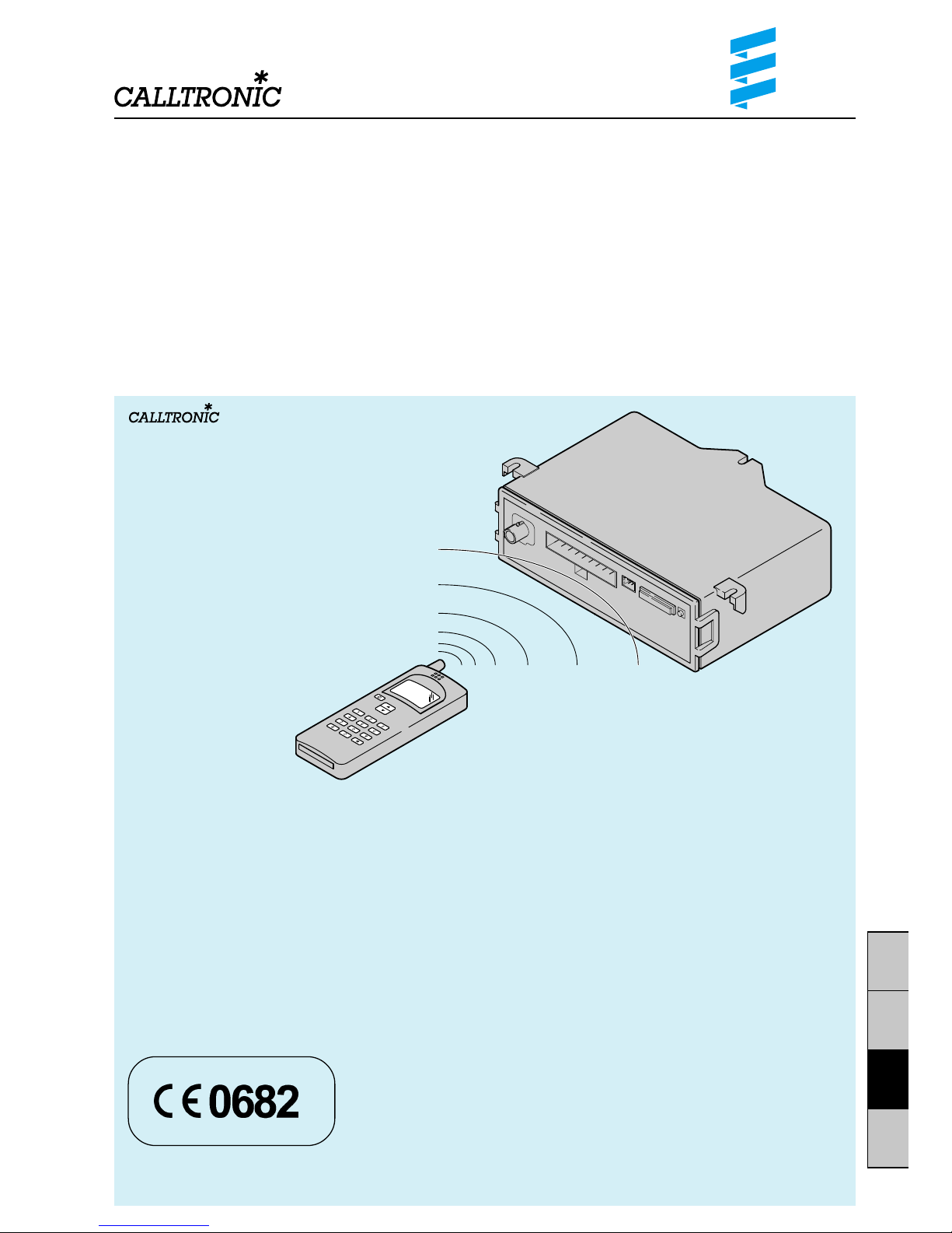
Telephonic remote control for Eberspächer
auxiliary heating
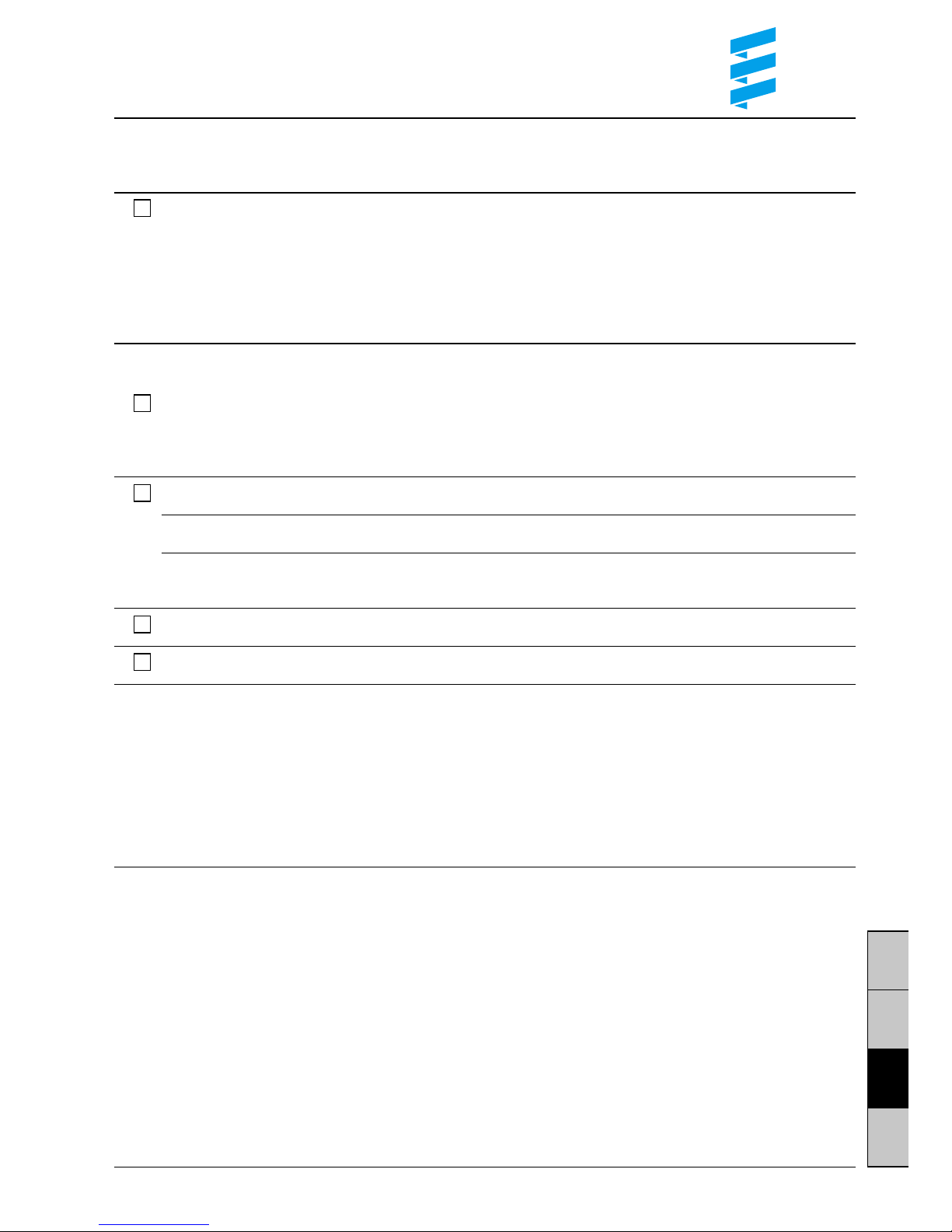
Extent of delivery:
1 GSM module (stationary part)
1 set of cables for heater
1 set of cables for mini clock
1 GSM windshield antenna
incl. cleaning cloth
1 push-button
1 tab connector housing, 6-pin
1 push-on contact housing, 6-pin
6 Junior timer contacts
3 screws
A SIM card from a mobile phone network operator
is required to operate the
CALLTRONIC
.
The mobile phone is not included in the extent
of delivery!
Order number – CALLTRONIC 12 V:
22 1000 32 26 00
Additional components (Optional):
Mini clock
Order No. 22 1000 31 31 00
Page 2
2
D
S
GB
F
Contents Page
Operating instructions
Operating the
CALLTRONIC
.................................. 2
General operating information ............................... 2
Reset PIN .............................................................. 2
Operating modes ................................................... 3
Operating the heater via the numeric keys
on the telephone ...................................................3
Functions
a) Select heating / ventilation mode .................. 4
b) Heating / ventilation running time .................. 4
c) Special functions ............................................ 5
Fault correction .....................................................5
Contents / Operating Instructions
Operating the CALLTRONIC
The
CALLTRONIC
is an operating element, to
remotely operate the heater with a DTMF telephone
or mobile phone via the GSM network from a distance. You can select between the heating and
ventilation operating modes. The following setting
times are available for the heating period: 10, 20,
30, 40, 50, 60, 90 and 120 minutes.
If preselected mode is required, a mini clock must
be used instead of the push-button.
Hazard!
• Pacemakers and hearing aids can be negatively
influenced.
• The SIM card and the SIM cardholder can be
removed at any time – small children could
swallow them.
Please note!
• When calling the
CALLTRONIC
, additional costs
are incurred due to the telephone charges.
• The range depends on the network operator
(“radio hole” – transmission gaps).
• It is important that the vehicle manufacturer’s
instructions and regulations for the installation
and operation of a mobile phone or GSM module
are observed and complied with.
• The
CALLTRONIC
can only be operated with an
external GSM outdoor antenna in vehicles with
a metalised windscreen.
General operating information
• The voice output has to be waited for before entering the numeric key, otherwise the function of the
key will be ignored.
• The connection is terminated after 30 seconds
without input.
• Reset PIN:
If you have forgotten your PIN number for setting
up the connection to the
CALLTRONIC
, you can
reset it as follows:
11. Sit in the vehicle.
12. Switch off the heater if it is switched on.
13. Phone the
CALLTRONIC
using the telephone.
14. Use the push-button or the mini clock to switch
the heater on following the voice output “Enter
PIN“ within 30 seconds. At the end of the 30
seconds, the heater must be switched on,
otherwise the programme is aborted and the
process has to be repeated.
15. Wait until the voice output “PIN invalid“.
16. Voice output “Enter PIN“.
17. Enter the PIN number “0000“.
18. Voice output “Enter PIN“.
19. Enter the PIN number “0000“ again.
10. Voice output “PIN OK“.
11. Voice output “Input function“.
The PIN number “0000“ is now stored for starting
the device.
You can change the PIN number at any time, as
described in the table on Page 5.
Page
Installation instructions
Installing the
CALLTRONIC .................................
6
Attaching the windscreen antenna .......................6
Insert SIM card ...................................................... 7
Installing the operating elements ..........................7
Insert fuse and check function ............................. 7
Technical data ....................................................... 7
Circuit diagrams parts list ..................................... 8
Circuit diagrams at the end of these instructions
Page 3
3
D
S
GB
F
Operating the heater via the numeric
keys on the telephone
You first have to set up a connection between the
telephone and the
CALLTRONIC
.
To do this, dial the number assigned to you by
your network operator.
The
CALLTRONIC
signals the following text:
“Eberspächer heater – Input PIN“.
Now enter the 4-digit PIN No.
(The PIN is set to 0000 in the works).
The following 3 operating modes
are available
Note:
If malfunctions occur in the heater during operation
(e.g. due to a lack of fuel), these can be interrogated after the malfunction has occurred using
Function 6 (where the diagnosis cable is connected).
The malfunction is corrected with the aid of the
operating instructions for the heater.
1. Stand-alone operation
The function keys 0 to 7 are active at the telephone
(see the following table).
The push-button installed can be used to switch the
heater on or off. If the heater is switched on using
the push-button, the heating function is activated
with a duration of 40 mins. The push-button also
functions without a SIM card. The push-button
flashes if an error occurs in the heater.
2. Combination with mini clock
The function keys 0 to 3 and 5 to 7 are active (see
following table).
The functions of the function key 4 (Select operating
mode) are taken over by the mini clock (see installation and operating instructions for the mini clock).
When switching on the heater via the mini clock, the
operating mode last set with the mobile phone is
always activated. If a malfunction occurs in the
heater, the reading in the mini clock display changes
between the time and “--“.
If the
CALLTRONIC
is connected with the mobile
phone, “--“ appears in the mini-clock display.
3. Combination with mini controller
When combined with the
CALLTRONIC
, the mini
controller only serves to specify the set value.
Select heating mode at the mini controller. The red
LED in the mini controller only serves as an operating display – not as an operating mode display – the
operating mode is selected via the remote control.
If the PIN No. is wrong, the following message
appears:
“PIN invalid“.
You now have the opportunity to enter the correct
PIN No.
If the PIN No. is correct, the following message
appears:
“PIN OK – Input command“.
You can now enter your settings for the heater via
the
CALLTRONIC
.
The following table on Pages 4 and 5 shows which
functions are available to you.
Page 4
4
D
S
GB
F
Functions
a) Select heating / ventilation operating mode
Numeric key Function Voice output
0 Switch off operating mode Heater off – Input command
(heating / ventilation)
1 Activate heating mode • Heater on – duration... minutes – Input command
• Heater on (only for mini clock) – Input command
2 Activate ventilation mode • Ventilation on – duration ... minutes – Input command
• Ventilation on (only for mini clock) – Input command
3 Status check • Heater on – duration ... minutes – Input command
• Heater on (only for mini clock) – Input command
• Ventilation on – duration ... minutes – Input command
• Ventilation on (only for mini clock) – Input command
• Heater off – Input command
b) Heating / ventilation running time
(If the mini clock is connected, the following function for numeric key 4 does not work)
Numeric key Function Voice output
4 Input duration • Input duration
Heating and Ventilation • Input invalid – Input command
(Only if mini clock connected)
1 Select duration 10 mins. Duration 10 minutes – Input command
2 Select duration 20 mins. Duration 20 minutes – Input command
3 Select duration 30 mins. Duration 30 minutes – Input command
4 Select duration 40 mins. Duration 40 minutes – Input command
5 Select duration 50 mins. Duration 50 minutes – Input command
6 Select duration 60 mins. Duration 60 minutes – Input command
7 Select duration 90 mins. Duration 90 minutes – Input command
8 Select duration 120 mins. Duration 120 minutes – Input command
9 No function Input invalid – Input command
0 No function Input invalid – Input command
Page 5
5
D
S
GB
F
c) Special functions
Numeric key Function Voice output
5 The following language is selected by pressing Key 5.
Repeat the function until the required language is announced.
Language selected: Input command
• German (in the selected language)
• Swedish
• English
• French
The following function, numeric key 6, only applies for the trade appliances (retrofit) –
diagnosis cable (blue / white) must be connected
6 Enquire heater condition • Heater OK – Input command
(Diagnosis analysis) • Heater not OK – Input command
• Input invalid – Input command
(if diagnosis cable not connected)
7 Change PIN Input new PIN
xxxx Enter new PIN Input new PIN
xxxx Enter new PIN • PIN OK – Input command
(for confirmation) • Input invalid – Input command
8 No function Input invalid – Input command
9 No function Input invalid – Input command
Problem Possible cause Possible corrective measure
No connection No supply voltage Check fuse and wiring
to the CALLTRONIC Weak signal Change location of the vehicle; check antenna
Outside of the GSM supply area Check the supply range of the network operator
Network block set Check network blocks
Network overloaded Call again later
SIM card invalid Call using another phone network operator
SIM card incorrectly inserted Ensure that the SIM card has been correctly
inserted; the card holder must lock home
SIM card contacts soiled Clean the SIM card with a dry cloth
SIM card with wrong number Only SIM cards with 3 volts possible
of volts
SIM card damaged Carry out a visual check;
give SIM card back to network operator
Fault correction
If problems occur while you are using the
CALLTRONIC
, first try to find a solution in the
following list.
If the problem continues, please contact an
Eberspächer service workshop.
Page 6
6
D
S
GB
F
Installing the CALLTRONIC
The
CALLTRONIC
is only installed in the inside of the
vehicle in accordance with the installation drawing.
Wherever possible, the installation position should
not be subjected to direct sunlight.
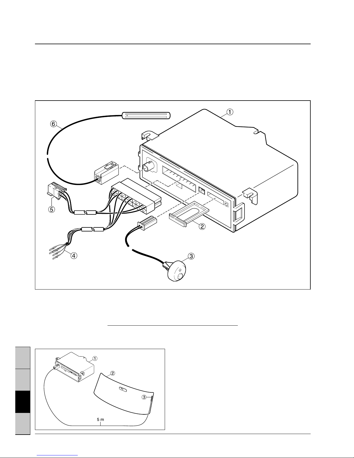
Attaching the windscreen antenna
The windscreen antenna is attached to the inside
of the windscreen or rear window.
Assembly:
Before sticking on the windscreen antenna 햴, the
relevant position on the screen 햳 should be cleaned
using the enclosed cloth and should be dry.
Pull off the protective strip from the sticky tabs.
Install the antenna cable to the
CALLTRONIC
햲 and
connect.
Note:
Length of the antenna cable: 5 m.
Installation Instructions
Please note!
• The SIM card should be able to be replaced even
when installed.
• Please ensure that you observe and comply with
the instructions and regulations of the vehicle
manufacturer with respect to the installation and
operation of a mobile phone or GSM module.
햲
CALLTRONIC
햳 SIM cardholder
햴 Push-button with LED
햵 Heater cable
햶 Mini clock cable (optional)
햷 GSM windscreen antenna
Page 7

7
D
S
GB
F
T echnical data
Working Voltage: 12 Volts
GSM Bands: Dual Band EGSM900
GSM1800
GSM Class: Small MS
Transmit Power: Class 4 in EGSM900
Class 1 in GSM1800
Operating Temperature: –20 °C to +50 °C
Storage Temperature: –30 °C to +85 °C
Dimensions: 140 x 100 x 36 mm
You must insert the SIM card before you can use the
CALLTRONIC
:
햲 To release the lock on the SIM cardholder, press
the yellow button – the SIM cardholder springs out
a bit.
햳 Pull out the SIM cardholder.
햴 Insert SIM card with chip (contacts) facing
upwards.
햵 Re-insert the SIM cardholder in the appliance,
until it locks into place.
Note:
Only SIM cards without a PIN and with 3-volt
technology can be used.
Installation of the operating elements
Push-button
Fit the enclosed push-button in the view of the driver
(Drill hole 10 mm, max. wall thickness 2.5 mm).
Connect the cables in accordance with the circuit
diagram.
Mini-clock (Option)
Install the mini clock (separate add-on) in accordance with the instructions supplied. Connect the
cables in accordance with the circuit diagram.
Insert the SIM card
Insert the fuse and check the function
The operating element must be connected and fully
functioning before inserting the fuse.
Insert the
CALLTRONIC
(5 A) fuse and check the
function of the
CALLTRONIC
after approx. 30 seconds (time until the GSM module has signed on to
the network) with a telephone or mobile phone.
Please note!
The heater diagnosis cable (blue / white) must be
connected for fault recognition (only for trade appliances – retrofit).
The operating element must be connected and fully
functioning before inserting the fuse. The appliance
detects whether a push-button or a mini-clock is
connected when the voltage supply is applied for
the first time. The
CALLTRONIC
does not accept
subsequent changes.
Page 8

8
D
S
GB
F
Please note!
The
CALLTRONIC
must be connected in accord-
ance with the circuit diagrams at the end of these
instructions. Note the type of heater!
Circuit diagrams parts list
2.5.4 Switch on relay
2.5.9 Ventilation relay
3.1.11 Round operating device
3.1.17
AIRTRONIC
mini controller
3.1.18
CALLTRONIC
push-button
3.2.12 Time switch mini 12 / 24 volts
3.2.14 Time switch mini lighting (only 12 volts)
3.3.8
CALLTRONIC
remote control
3.8.3 Antenna
a) Connecting the operating elements to the heater
• rt Plus supply, terminal 30
• ge Contact signal S+
• gr Actual temperature value
• ws rt Switch off theft warning system
• br Minus supply, terminal 31
• bl ws; bl Diagnosis
• gr rt Set temperature value
• br ws Sensor reference signal
• sw ws Switch on ventilation
z) Terminal 58 (lighting)
Insulate any cable ends not used.
The connectors and socket housing are shown from
the cable entry side.
Cable colours
sw = black
ws = white
rt = red
ge = yellow
gn = green
vi = violet
br = brown
gr = grey
bl = blue
li = lilac
Page 9

HYDRONIC B 4 W, B 5 W, D 4 W, D 5 W
25 1920 00 97 02 A
Page 10

AIRTRONIC – 1
25 2069 00 97 04 A
Page 11

25 2069 00 97 04 A
Page 12

AIRTRONIC – 2
25 2069 00 97 05 A
Page 13

25 2069 00 97 05 A
Page 14

B 1 L P compact, B 1 L C compact, D 1 L P compact, D 1 L C compact,
B 3 L P compact, B 3 L C compact, D 3 L P compact, D 3 L C compact
25 1895 00 97 03 A
Page 15

25 1895 00 97 03 A
Page 16

D 5 L C
25 1822 00 97 03 A
Page 17

25 1822 00 97 03 A
Page 18

D 8 L C
25 1766 00 96 02 A
Page 19

25 1766 00 96 02 A
Page 20

HYDRONIC 10
25 2044 00 96 03 A
 Loading...