

Page 1
Air
heaters
B5L/D5L
/
B5LC/D5LC
'.
Trouble.hooting and repair manual
The Troubleshooting and Repair Manual Is valid
for
the
following
heaters:
BOL
201707
05
00
00 -
12
Volt
20 1708 05
00
00 - 24 Vol1
D5L
2517290500
00 -
12
Volt
25 1730
05
00
00 -24 Volt
Contents
sectional view
___
_ ,
..... , ...... " .............
. ,
......................
,
Description
of
operation.
In the event
of
fault
s,
first
check
the following point
s",
Function and fault test...
Wiring diagrams
Repair instructions .
................
..........
. .
Measuring
the
fuel quantity" ..
Using the test adapter
25186195086
2 04.1995
ModifIca
tion
reserved.
BOLC
2017350500
00 -12
Vc>1
20
1736 05
00 00 -24
Volt
D5LC
251861
05 00
00
-12
VoI1
25
1862
05 00
00 -24
van
Page
2
3
4
4
.5
6. 7
8-13
14
15, 16
Printed
In
GIIrmany. C Copyright J. Eb6'spAchef
J. Ebersp
ilc
her
GmbH
&Co
Ebersp:tcherst
r.
24
0·73130
Esslinge
n
Telefon (
zentla
l)
(011 1) 939-00
TelelllJ(
(0111 ) 93>1
{)500
http:lt-w
.
eberspaec
he,-de
C29/C3O
Page 2
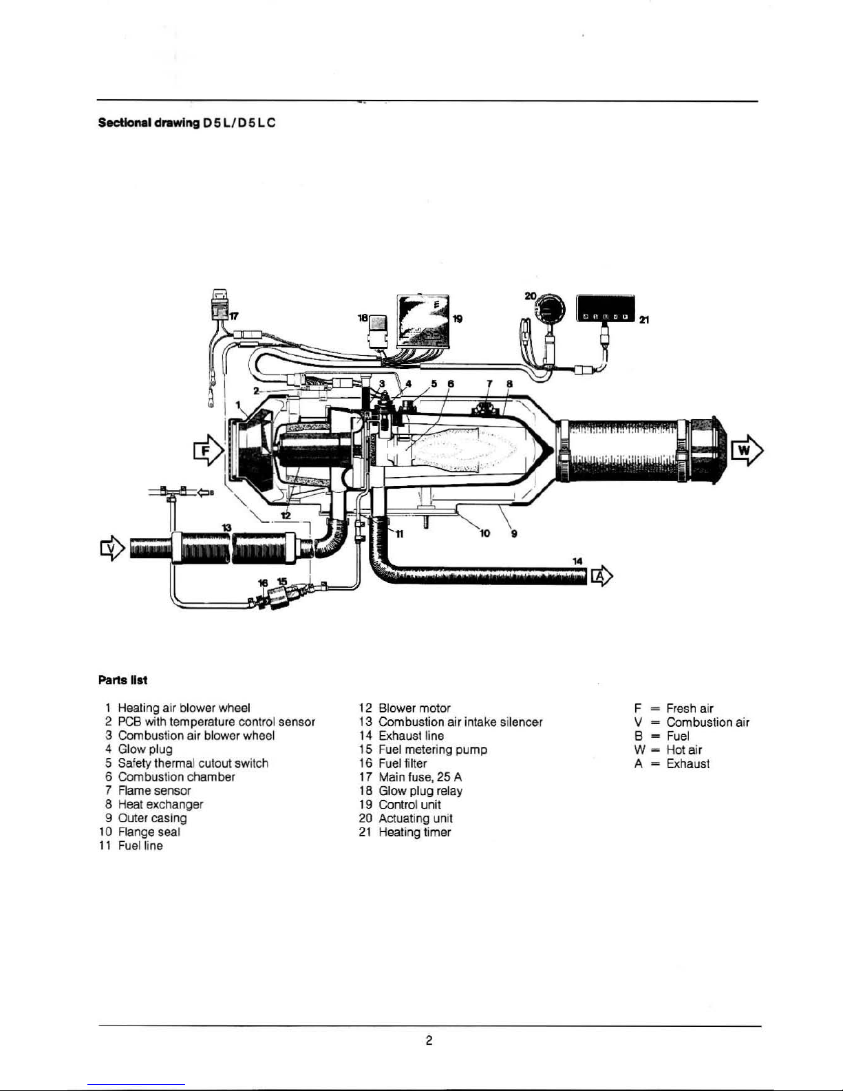
Sectionlil dl'llwtng 0
SL
ID 5 L C
Parts list
1 Heating air blower wheel
2
PCB
wi
th
temperature contrOl sensor
3 Combusti
on
air blower wheel
4 Glow plug
5 Safety thermal cutout switch
6 Combustion chamber
7 Rame sensor
8 Heat exchanger
9 Outer casing
10 Flange seal
11 Fuel line
Wi
12 Blower motor
13 Combustion air intake silencer
14 Exhaust line
15 Fuel metering pump
16 Fuel filter
17 Main
fu
se, 25 A
18 Gl
ow
plug relay
19 Control unit
20 Actuating unit
21
Healing timer
2
F
~
Fresh air
V
~
Combustion air
B
~
Fuel
W-
Hot air
A -
Exhaust
Page 3
_01
___
_---on
,
=;
Switch-on: green pilot light
in
the operating unit
~ON·.
After about 1 s&cond: healing coil of glow plug
NON-.
Blower 'ON" at full speed.
After
33 -
70
seconds: fuel
pump
·OW.
Once a stable llame has been obtained. the
glow
plug is
switched
off.
To
reach
the
operating temperature
of
the heat exchanger
quickly, the healer
is
operated
at
an
increased heating ca-
pacily
of
5.5
kW
after being switched
on.
Once
the
heat exchanger operating temperature
has
been
reached,
the
heating capacity is reduced
10
4.8
1NoI.
The
duration of heater operation
with
Increased capacity
depends
on
the
ambient temperature.
Reguldon
In heatlna opention
Once the intakelroom temperature as set at the operating
unit has been reached,
the
heater switches
to
the
"lOW"
setting and then continues to
run
at low blower motor
speed.
If
the
heating capacity
In
the
NLOW"
control setting
is
in-
sufficient,
the
heater switches to
the
"MEDIUM~
setting.
The
blower continues to operate
at
low speed.
In
most cases,
the
LOW/MEDIUM/LOW
settings
at
low
speed will provide
the
required heal.
If
the
heat
ing
capacity
in
lhe Q
MEDIUM"
sening
is
insuffi-
cient. the heater switches back to
the
-HIGW setling. This
entails full speed
tor
the
blower motor again. _
If
in
some cases
even
less heating capacity is needed
than
the
heater supplies in
the
"LOW' sening. the heater
switches to
the
·OFf" setting.
The
heater continues to
run
after shutdown, followed
by
constant after-ventilation prior to
restart.
The
constant after-ventilation applies only lor heaters
In
reci
rculated air mode.
The
subsequent restart is
in
the
-MEDIUMM setting
at
low
blower motor speed.
When
the
heater
is
finally switched
off.
the
green pilot light
goes out and
the
blower continues to
run
until
II
coots
down. During continued operation,
the
glow plug is
switched on
for
approx.
30
sees
. to dean it
of
combustion
residues.
Th
is continued operation will always
end
after about 4
to
5 minutes
at
low speed.
3
Control_nd
ufety
equipment
The
flame
is
monitored
by
the
flame sensor
(7).
the
maximum permitted temperature by the safety thermal cutout
switch (5).
Both
of
them affect the control unit
(19),
which switches off
the
heater in
the
event
of
fauNs
.
. 1.
If
the healer does not ignite wtthin 90 seconds of
the
start
of
fuel
pumping, starting is repealed as described.
If
the healer still does not ignite after a further 90 se-
conds,
fauN
shutdown follows.
2.
If
lhe flame goes out
by
itself during operation, a restart
follows
first.
If
the heater does
not
ignite within 90 seconds
of
fuel
pumping being switched
on.
or
It
does Ignite but then
goes out within
10
minutes, fault shutdown follows.
The fault shutdown can be cancelled out
by
briefly
switching
the
heater
off
and back
on
again.
3. In the event
of
overheating, the safety thermal cutout
switch (5)
leacts
,
the
fuel
supply is interrupted, and fault
shutdown follows.
If
overheating
is
the cause of a fault shutdown,
the
switch-on pilot light
(green)
in
the
operating unit flashes
steadily.
Once
the
cause
of
the overheat
has
been remedied,
the
heater
can
be restarted
by
switching
it
off
and then
back
on
again.
4. Further
fauN
indicating signals cen be obtained
with
additional equipment, and
are
described in
the
trouble-
shooting and repair Instructions
on
pages
4 and 5.
5.
If
the voltage drops
below about
10.5
or
21
V.
Of
rises
above
15
or
30 V as
the
cese may be, fault shutdown
follows.
6.
If
the glow plug
is
defective and the electric line to the
metering pump
has a break,
the
heater will
not
start.
7. When
the
heater
is
started
the
functioning of
the
blower
motor is checked
once.
11
it
does not
start,
the
heater
will undergo fault shutdown.
During operation,
the
blower motor
is
monitored
in
cyc-
les
(4
mlns.).
If
the molor speed
Is
below the permitted
limit,
lauN
shutdown follows.
PIe8
..
not.:
For
electric welding work
on
the
vehicle, the positive ter-
minal
of
the battery must
be
disconnected and earthed
in
order to protect
the
control
unit.
I
Page 4

e
Fuel
in
the tank?
eFusesOK?
e Electrical
lines
and
connecttons OK?
·
c.
• Combustion air and exhaust piping
!'Iystems
tree?
When
combustion produces
soot,
check
the
following:
Combustion air and exhaust piping systems clogged?
.........
Remove cause of clogging.
Fuel
metering pump conveying too much?
.........
Measure fuel quantity, replacing
fuel
metering pump
if
necessary.
Deposits
in
the
heat exchanger?
.........
Clean heat exchanger, or replace
illf
necessary,
Cliling
of
dIIlftOdc
......
18
Connec1
a switch to terminals 4 and 6 of
the
operating
unil.
Turn
on
the switch
and
compare the diagnostic signal
displayed
by
the
operating unit
with
the
list
on
page 5,
Deal
with
lhe Irouble
as
descnbed
under
'Remedy".
Checkweluee
Speed
of
blower
motof
in
HIGH
set1ing
: 5000
rpm
±10%
in
MEDIUM
and
LON
settlng5: 3000 rpm ± 10%
in continued
operation:
3000 rpm ± 10%
in
after
ventilation:
850
rpm
(
only
In
recirculated
air
mode)
4
Page 5
I
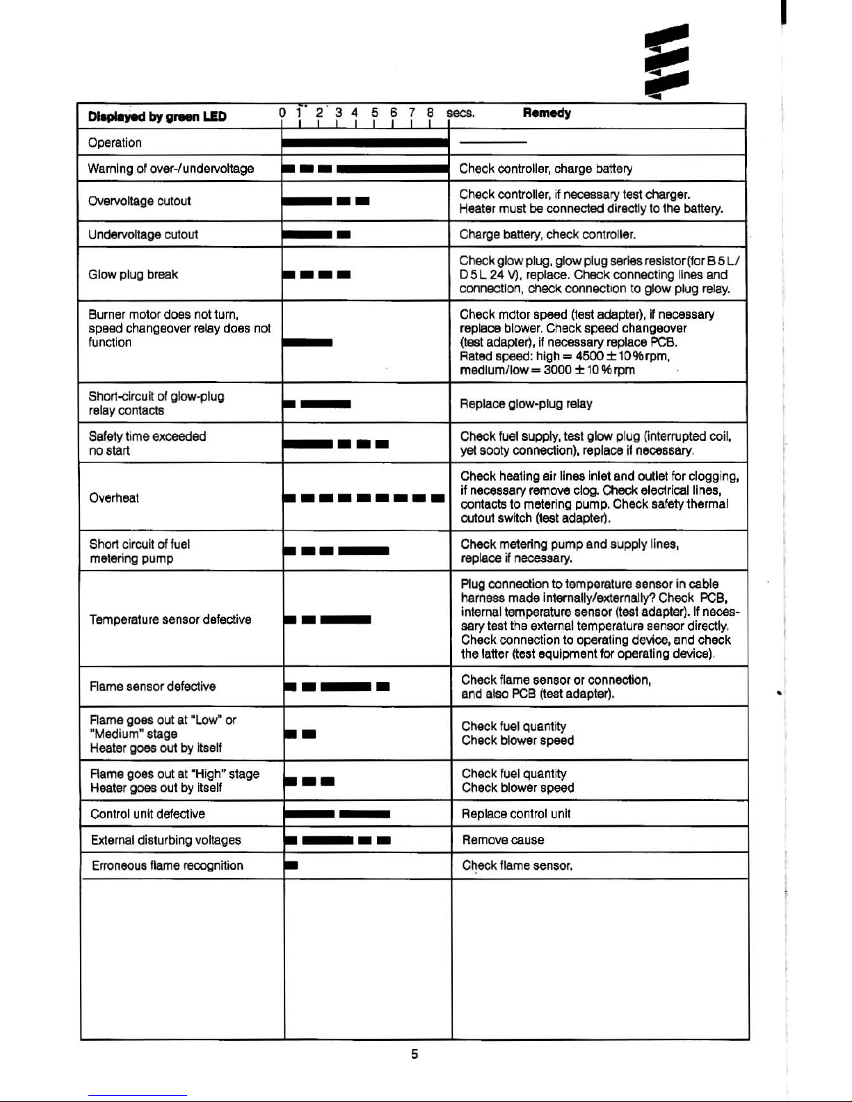
DIopIojod
by
......
LID o 1
2
31
r n r
SOCS.
A-.dy
Operation
Warning of olJer-lundelVoltage
•••
Check controller, charge battery
Overvoltage cutout
••
Check
controller, jf
necessary
test
charger.
Heater must be connected directly to
the
battery.
Undervollage cutout
•
Charge
battery,
check
control~r
.
Check
glow plug.
glow
plug
series
resistor(for B 5
LI
Glow
plug break
••••
05L
24
V),
replace. Check connecting lines
and
connection, check connection
to
glow
plug
relay.
Burner
motor
does
not
turn,
Check
mdtor
speed
(test
adapter),
If
necessary
speed changeover relay does nol
replace
blower.
Check
speed
changeover
function
(tast
adapter),
if
necessary
replace
PCB.
Rated speed: high =
4500±
10%rpm,
medlumJlow - 3000 ±
10
% rpm
ShOf1-circuit
at
glow-plug
~I
Replace glow-plug relay
relay
contacts
Saf~ty
time exceeded
•••
Check
fuel
supply, test glow plug 0nterrupted coil,
no start
yet
sooty
connection),
replace
if
necessary.
I
,
Check heating air lines inlet and outlet
for
clogging,
Overheat
~
.....
---
if necessary remove clog. Check electrical lines,
contacts to metering pump. Check safety thermal
cutout switch
(test
adapter).
Short circuil
of
fuel
~
..
Check metering pump and supply lines,
metering pump replace
if
necessary.
Plug
connection to temperature sensor
in
cable
harness made internally/externally? Check
PCB,
Temperature sensor defective
~.
internal temperature sensor
(test
adapter).
If
neces-
sary test
the
external temperature sensor directly.
Check connection
to
operating device, and check
the latter (test equipment
for
operating device).
Flame
sensor defective
~.
•
Check flame sensor or connection,
and
also
PCB
(test
adapter).
•
Rame goes out
at
"Low"
or
••
Check fuel quantity
-Medium" stage
Check blower speed
Heater
goes
out
by
Itself
Rame goes out
at
"
High~
stage
•••
Check
fuel
quantity
Heater goes out
by
Itself Check blower speed
Control unit defective
Replace control unit
External
disturbing voltages
•
••
Remove
cause
Er
roneous
flame reoognition
•
Check flame sensor.
5
Page 6

'"
·UD
,
I"
.
.......
. ,
..
c ....... . ,_
, I
~ t~=, ·~·'
......
"
1.1 Burner
motor
1,2 Glow plug
1.5 Safety thermal
cutout
switch
1.7
PCB
with temperature control
sensor, speed change and
multiple-blade
connector
1.12
Aameaenaor
1.13 Tcmperaturesensor
2.1 Control unit
2.2
Fuel metering
pump
2.5.1 Glow plug relay
2.7 Main fuse.
25
A
IUD
,O!
,
i
~
<
~
i
:.a
(ill
3.1.11 Actuating unit
3.1.12 Fauhcodeenquiry
3.2.3
Timer, digitel
.•
quare
3.2.4
Timer, digital. rectangular
5.1 Battery
,
,
,
1$,""-
~
f-
•
I i] I
25172900
96
01
C
_)
test
(wOfbhopl
digital
timer
b)
to terminlll15
c)
lighting, terminel58
dl
if
timer
Is connected,
break
lin.
here
81
If
tempenltlire sensor is connected.
<M1ach
existing socket housing and fit
todc:et
houlirtg
of
tempenture
sentor
:;;
s:
,s
I
~
.
I
..
..
r-
,
o
'"
r-
I
-
'"
R
Page 7

i
(ill
~
!
~ @~
i
-
ljg
dt
.
.,
F-J
""
I
},
/.],
<ID
~
,
<=
I
a
.
~
.
~
~
(ill
U:.
.
•.
..
-
..
...
t •
•.
_ ·
·_
..............
~
. ''''''
--
/
I
.
.1..1.5..2..1
ll
IT,
;;D
[]A
LL
A.LIR
Il.
, T
CID
1.1
Bumermot
Of
1.12
Fla
me sensor
1.2 Glow
plug
1.13 Tempera
tu
re sensor
1.2.1
Gl
ow
plug resistor
2.1
Control un
it
1.5
Safety
thermal cut
out
switc
h
2.2
Fuel metering
pump
1.7
PCB
with
temperatur
e control
2.5.1
Glow
plug
relay
se
nsor,
speed
chenge and
2.7
Main fuse,
25
A
multiple-blade connecto
r
<ID
~
®
cflI,,'s@!
:,<j
<=
..
-~ ~W
.
~
f
H::-J
I
CDD_ ..
.
r,.
,.-,{
~
l
nr.:'1
~1
.
LJL;'T
~
1
--1:J
I
[
~
'T'
~
r
·
~
"
J
~
.
~
,,
4~
~
Is
~
(3.1.12)
ill)
2
51730
00
96
01 C
3.1.
11
Actuat
ing un
it
0'
teat (
wo
rkshop)
digital
ti
lT'lM
3.1 .12 Fault code enquiry
b'
to t
enni
nal15
3.2
.3
Timer,
dig
ital. square
.,
li
ght
ing, terminal
58
3.2.4
Timer, digita
l. rect
angular
.,
if
timer
15
connected.
5.1
Ba
tte
ry
braak
lina
hare
. ,
if temperatura sensor is connected •
detach existing
socket housing and fit
sock
et:
housing of
temperature
. sensor
,
ID
'"
,...
,
c
'"
,...
,
:1
;;
,.
'ttl
Page 8

Wiring dillgrom -
B5LC/D5LC
---
-~
--
~~
;-r
I:':IHI~
l.',,'
L'"Jft_
u_
--'
I !
CIT
em
<TIl
hrts
u.t
1.1 Burner motor
1.2 Glow plug
' .6 Safety thermal cutout switch
1.7
PCB
with controller temperature
,ensor, speed regulator
and plug distributor
1.12 Fleme monitor
1.
13
Temp.retur sensor
••
--'-'
"""'"
1.1
---I
I,..,
I~~~
1 1 1 'I' 1
IIW
1 1
@D
1 1
1 1
1 1
-
: :
" .
~
~.
!
-
,
~tifU
Ie
[]A
T T
2.1 Controt unit
2.2
Fuel
metering pump
2.5.1 Current
r-suletor
2.7 Main fuse
126
Al
3.1.12
Fault
cod.
enquiry (garllge)
5.1
Battery
8
251830
00
96
01
' 1 to connect
the
tMnperature MnSCW.
detach
the
receptacle housing
provided and fit the receptacle
hcuaing
of
the
temp.retur.
senIOr
instead.
!ill Connection control elements
to h
••
ter
Plug housi
ng
and locket housing ahown
from the
lid.
where line enters.
Page 9

h'
Wiring dIag
.....
-
B5LCfD5LC
51
GlD
"
51
.DII
••
ac;;
51
"
52
8Z
5l
-.~
'"
~
~
RJ"
1=1
1:
1
H
~:!
.
0.1
...
~
1:1
<fl
~
:
I-I
UD
1_
H
"'I
bl
1=1
•••
Li!~
.
-.
1-1
~l~
~l~
¥:+=:::=-::JS'l
V
I
'_,_,_.="
I
':
I:
t;-r;t I'
f'l;,
5'
I
l!:t1.
~I
~
1.
• J
Bl
..
B5
,
1)
ffi
• •
• •
· ,
•
II
II
I'll
51
(ill)
~
~.[Il
•••••
.
~
I
8Z
I~
"
(ill)
rmm
Bl
-y-
'1:-1
fiII~'
~
..
j.
...•
..
,",
,
'bit
1:1
.,11:11
J •
1::1
1
i~1
I~
!'
r'"
Il
l:1
I:I~
I
I'
1;1
1;1:::1
1
.i._
_,_,_._._._
---
I
,
I
.,
I
,
I~
..
aID
I I
.!
I
II
•
' M
,
!-
'.
i_
-
----
-
......
,
I
I.!
al1l
,
...
1
0.5_
0
,
52
.
~l~
Ii
B2
B2
S2
,
."
IDL.!
53
III
FI
'
(liD
51
I
~,
' M
,
:F
,
•
o.
,
I
PIIrt.
List
2.15.9 S.nlOr,
.xt.rn.'
t.mp
....
tur.
3.1.1 1 Op.r.tlng unit
3.1
.12 Fault code enquiry (garage)
3.1.13
Op.r.tlng unit
3.1.14 Operating unit
3.2.5 Timer
3.2.6 Tlm.r
3.2.7 Timar
"
..
<liD~
m:~
I'
E11
r'
...
",
I~I:
...
j<I'
1 ' ,
,(,- , ,
la=lt:S':Jtj-
..
,
[;
l •
3.6.1 Cable harness
for
3.1.
11
3,6,2 Cable harness
for
3.
1.13
3.B.3
Cabl.
harn.
s.
for
3.1.14
3.6.4 Ceble harness for 3.2 .7
3.S.1 Timer relay
9
251112200 97
01
C
al
Te"
(garag') digital timer
b)
to terminal 15
c)
lighting t.rmin.1
68
d)
break line here to connector
tim.r
f)
3.2.
6/
3.2.
6/3.2.7
to be
connected here
g) Connection control elements
to
h.at.r
hI
Remov. S 3 and
fit
S 2
Page 10

r
1
22
1 Combustion air blower
2
Blower wheel
3
Cover
4 Uning
5 Seal
6 Blower
7 Seal
8
PCB
9
Heat
exchanger
10 Cover
11
Seal
.
•
~
-
"".
-
"
10
17
12 Safety thermal cutout switch
13
Flame
sensor
14 Plug strainer
15 Glow plug
16
Series resistor
(for
BSL/D5
L 24 V only)
17
Upper
casing half
18
Lower
casing
half
19 Intake end piece
20 Outlet end piece
21
Flange seal
22 Sealing
23 Carrier
Page 11

--
1.
Remove
cable
harness
plus
cap
2.
Rem
ove glow plug
3.
Remove plug strainer
4.
Remove
PCB
5. Remove outlet end pi
ece
6. Remove upper casing
half
end upper
heat protection plate
7. Remove safety thenna! cutout switch
1. R ....
ove o.bIe
hi.,....
plUi
ClIp
Unscrew the cap
from
the heater and detach the plug
connector
from
the
PCB
and glow plug.
2. _
glow
plug
Unscrew the glow plug conn9dQf.
Unscrew the glow plug.
When fitting _ new glow plug,
pI
__
note
the
following:
Check the plug strainer in the glow plug connection, clean
it
if
necessary, or failing that replace
it.
3. Remove
plug
etIIIlMI'
Take
the plug strainer out
of
the plug connection usi
ng
pliers.
Clean the plug
st
raine
r,
replace it if necessary .
•
."."".ntIWhen
fitting the plug strainer. ensure the nose
is
in
the right position.
Slide in the plug straine r carefully
as
far
as
it
will go.
Th
e hole for plug area ventilation must then
be free.
11
a.
Remove
flame
sensor
9.
Remove
series
resistor
for glow
plug
(8
5L105L
24
Von~)
10. Remove
blower
wheel
11.
Remove cover from blower
motOf
and
f
it
new lining
12. Remove
blower
from
heat
exchanger
13, Remove cover from heat exchanger
I
Page 12

4.
Aemove
PCB
Detach
the
plug connector
from
the
PCB
.
Press
the
PCB
downwards
and
pull
it
out.
5.
___
"'-
· .
Unscrew
the
four
fastening
screws
of
the
outlet
end
piece,
then
remove
the
end
piece.
e.Romoveu
__
hoII
__
_
protection
-
Unscrew
the
fastening screws
of
the casing
half,
then
remove
the
casing
half.
Remove
both
securing clips
from
the
heat
protection
plale.
Remove
the
heat
protection
plate.
ImpotUlnt
: Use
new
securing clips when putti
ng
the heat
protection plate beck in.
12
Page 13

7. Remove safety thermal cutout switch
De
tach t
he
plug connector from the
PCB.
Remove both securing clips from t
he
safety therma l
cutout switc h.
Remove the safety
thermal cutout switch.
Important! Use new securing clips when pulling the
safely
thermal cutout switch back in.
Removing the safety thermal cutout
SWitch
8. Remove flame sensor
Remove the retaining spring wi
th
a screwdriver.
Remo
ve
the lIame sensor and the intermediate piec
e.
See
also page
12.
Fitting the safety thermal cutout switch
13
Page 14

Removing the flame sensor
9. Remove series resistor for glow plug
(
85
L ID 5 L 24 V only)
Note on removal:
The series resistor is f
i"ed
with a clamping ring,
not a thread!
Unscrew the connectio n at the series resistor.
Remove the series resistor as shown in the f
ig
ure.
Fitting the series resislor:
Drive the series
res
istor with an
18
x 1 diameter pipe
into its mounting by
lighl hammer blows.
10. Remove bktwer whee'
Remove the lock ring from the blower wheel using a
screwdri
ver.
Pull the blower wheel off the shalt of the electric molor.
Filling the flame sensor
14
Page 15

11.
"-nove
c::cwerfrom
blower motor end tit
new
1InI""
Un
screw the
fas
tening screws from the cap. Remove the
cap, and
fit
a
new
lining
if
necessary.
Importantl When
fitti
ng the cover, u
se
only the original
screws or
new
ones
(Taptile M5 x 1
2).
13. Removecovertrom hMtexchenger
Unscrew t
he
fastening screws from the cover. lift the
cover off the heal exchanger using an angled hook
through
th
e exhaust connection.
Importantl Slide the pipe
of
the combustion air system
i
nt
o the caver.
When fitting the cover,
use
a new
seal.
When
fitting
the caver,
use only the original
screws or new ones (Taplite M5 x 1
2)
.
1 Heal exchanger
2 Cover
3
Pipe
of
combustion air system
15
12. Remove blower from heat
.xct.nger
Un
screw the
fas
tening screws from the support. Remove
th
e support trom the blower.
Un
screw the fastening screws from the blower.
Rem
ove
t
he
blower and dear the heal exchanger and blower
of
sealing residues.
Importantl When assembling the heal exchanger and
blower, replace the
seal.
5
1 Cover
2 Lini
ng
3 Support
4
Blowe
r
5 Heal exchanger
1
Page 16

M_rtno
lIMo
fuoI_
IMPORTANTl
Only measure the fuel when the battery is
sufficienlly charged.
AI least 11/22 V or
max.
1
312
6 V
shou
ld
be
applied to the control unit
during
measurement
1.
__
Detach the
plug
connector under the cover cap
on
the
healer
and
connect a lest lamp. Detach the
luelline
from
the healer
and
insert
it
into a measuring glass.
Connect a voltmeter to the 4-pin
plug, terminals 3 (+)
and
4
H,
of the control unit.
Switch on the heater; when fuel is being
pumped
steadily
(around
25 -55
sees. aft
er s
witch-o
n),
the
fuel
line
is
filled
and free of air.
Switch o
ff
the heater
and empty
the measuring glass.
2.
Meuurement
Switch
on the healer.
Fuel is
pumped after about
25 -55
sees. aft
er switch-on.
Hold the measuring glass
al
the level of
lhe
plug during
measurement.
Read
off
the
voltage at the voltmeter.
After 90
sees.
of fuel p
um
pin g, this stops automatically.
Switch
otlt
he heater.
Read off the fuel
quant
ity In the measuring
glass
.
Test ap.,.ret:ue
------,
3.
Evaluation
Transpose the readings onto the graph.
Fuel consumpti
on
is
OK
when the inler
s9CI
ion 01
roth
vatues
is within the limit curv
e.
If the intersection is outside
the CUNe,
the lu
el
metering
pump must
be
replaced.
~
OOSek
21
,---------
-,
----
----
-,
19
r---------
-+----
~
17
15
1
3r---------t-
--------~
11
r-
--------t---------
~
9
7
---
~
11
22
12
24
13
26
Vo/1
The fuel metering pump, when swi1ched on, supplies:
-lor B 5 L the fuel quantity for the
~
High
~
setting.
Rated quantity at 12
Vl24 V"'"'
16
.25
ml/90
sees .
• for 0 5 L the fuel quantity for the
~
Medium~
setting.
Rated quantity at
12
Vl24 V - 8.5
ml/90
sees.
=
oon1l0l unH
Voltmeler
'~
B[A"
0
0
"0
~
, ,
, .
'"
'
,,-=
---
,
j
Test~mp!!
Q
~=
16
~
--
/tw
,
Connection
01
vOltmeter to control uM
Page 17

-.
U.&ng
the
teet
adapter
and
the
test Instrument
for
the
oper1ItIng
unit
To
identify certain
faults
(see
page
5),
the
test adapter
(PCB)
and
the test instrument for the operating unit a
re
necessary.
1.
T..tIng
the
blower motor
Detach
the plug fr
om
the PCB. instead conn
ect
up
a lest
adapter. A
ppl
y operali
ng
vol
tag
e +
and -10 the adapter.
An o
hmm
eter is
nol
required for this measuremenl
Th
e blower
molor
mus
t start
up
at once.
Measuring the speed:
Switch
closed,
3000
rpm
Swit
ch
open,
800
rpm
Press button: the mo
lor
switches to high speed,
5OCX)
rpm.
"
the
motor does
not
run
:
Ch
eck
PCB visua lly for burnouts.
If OK, c
hange the
blower.
If t
he
speed changeover does not work, change
the
PCB.
2. T
..
ting the
Ntety
thennal
cutout
,witch:
The test
lamp must come
on
as
soon
as the operati
ng
voltage
has
been co
nnected.
11
it
does not
come on,
check
the PCB, cable, plug con-
tacts for breaks, ch
eck
the safety thermal cutout switch for
continuity.
Teat
adapter
for PCB
3.
Tutlng
the
temperature
.ensor
(lntemal)
and
flame
..
ntor:
The internal temperature
sensor
arranged on the PCB and
the flame
sensor arranged on the heat exchanger can
be
tested as follows (operating voltage
does
not ha
ve
to
be
co
nnected) :
Connect an
oh
mmeter to
the test adapter
as
shown
in t
he
sketch. The values given in
the
ske
tch mu st
be
complied
with.
In the event of a fault, check the PCB for breaks
or
short-
cir
cuits.
If
the
tempe
rature sensor is defective, replace the PCB;
il the
fl
ame senso r value is
00,
replace the
Ilame
sensor.
"
an
external temperature
senso
r
is
co
nnected, its res i-
stance
va
lue
must
be
in the
same
range. For this purpose,
co
nnect the extemal temperature sensor directly to the
ohmmeter.
,)
1 br/ws
2
swlge
..
-----
·
~I
2
6
7 gr
8 sw/ws
17
I'
7
18
12
19
6
10
br
~O16
9
In
~,
10
11
,
l1rt
~
...
12
12
br
Temperature sensor
1
800 -22
000
Flame sen
sor
900
-11()()0
whe
n heater is cold
(when heat
exchanger is ho
t,
up
to
22000)
-----
-----
~
~
Test la
mp
co
thermal cutout
mes on
when safety
switch
is
OK
+
~
Pushbutt
on: speed changeover
to
5000
rpm
Switch: speed changeover fr
om
800 r
pm
to
3000 rpm
17
Page 18

Teet unit for
opeq
tlng de¥ice
Delach Ihe plug of the operaling device from the cable
harness, inslead connect Ihe lesl
unill
o Ihe operaling device, and apply operating vonage.
Sellhe switch on the operating device 10 Ihe -Heating
and Vemilation" position. The appropriate lights must
come on.
The pilot light in the switch must
also come on
.*
• This test is unnecessary
in
operation with heating timer.
Tnt
unit
for operating device
-
----
gn
1 .
1800-
22
000
~pl
gn
,3
Ventilation
4
'5
6
' 9
±
L::.
___
18
Turn off the switch in the operating device. Call up lighting
wi
th key 1.
Pr
ess key 1, press key 2 in addilion.
Pi
lot lig
ht must change from
red
to green.
Connec1 ohmmeler, turn ralary knob. Set value of 800
10
1200 must be maintained without a break.
tn the event
of
an error change the operating device .
sw
--
'
---
'
- Key 2
lEO
green
+ Key 1
lig
hting red
t
. _
____ . ...l
 Loading...