

Eberspächer AIRTRONIC L – B5, AIRTRONIC L – D5 Troubleshooting And Repair Instructions
Eberspächer
J. Eberspächer
GmbH & Co. KG
Eberspächerstr. 24
D-73730 Esslingen
Phone (switchboard)
(0711) 939-00
Fax
(0711) 939-0500
www.eberspaecher.com
L
25 2361 95 16 95 04.2008 Subject to changes Printed in Germany © J. Eberspächer GmbH & Co. KG
Troubleshooting and Repair Instructions
The troubleshooting and repair instructions are only
applicable to the following unit versions
AIRTRONIC L engine-independent air heater
for petrol engines
Heater Order No.
AIRTRONIC
L – B5, 12 volt 20 1859 05 00 00
AIRTRONIC L engine-independent air heater
for diesel engines
Heater Order No.
AIRTRONIC L – B5, 12 volt 25 2361 05 00 00
AIRTRONIC L – D5, 24 volt 25 2362 05 00 00
2
4
3
1
1
Introduction
This list of contents gives you precise information about the
contents of the Troubleshooting and Repair Instructions.
If you are looking for a term, technical term or you would like
an abbreviation explained, please use the relevant index at the
end of the instructions, from page 53.
Introduction
Function
Product information
Troubleshooting
• Contents .................................................................................................. 2 – 3
• Foreword ....................................................................................................... 4
• Safety instructions for installation and repair ................................................... 4
• Accident prevention ....................................................................................... 4
• Special text structure, presentation and picture symbols ............................... 4
• Important information before starting work .................................................... 4
• Cutaway view ................................................................................................. 5
• Functional description ..................................................................................... 6
– Switching on ............................................................................................... 6
– Control in heating mode ............................................................................... 6
– Ventilation mode .......................................................................................... 6
– Switching off ............................................................................................... 6
• Control and safety devices ............................................................................. 7
• Forced shutdown ADR / ADR99 ..................................................................... 7
• Emergency stop (EMERGENCY OFF) ............................................................. 7
• Technical data AIRTRONIC L – petrol / diesel ................................................. 8
• Check values .................................................................................................. 9
– Test speed for the blower ............................................................................ 9
– Resistance values ........................................................................................ 9
– Switching value ............................................................................................ 9
– Exhaust emission specification ..................................................................... 9
– Check “external” temperature sensor ........................................................... 9
– Table of values – “external” temperature sensor............................................ 9
• What to check first in case of faults ............................................................... 10
– Check ........................................................................................................ 10
– Electrical components ............................................................................... 10
– Measure battery voltage ............................................................................ 10
– Measure voltage supply (CI 30) .................................................................. 10
– Check switch-on-signal .............................................................................. 10
– Check control unit ...................................................................................... 10
• Overview of the individual test equipment and control units ..........................11
• Locking the control box ................................................................................11
• Cancel the control box lock .......................................................................... 11
• Check control unit ........................................................................................ 12
– Before the test .......................................................................................... 12
– Check the setpoint potentiometer of the control unit .................................. 12
• Fault diagnosis using the diagnostic unit ................................................. 13, 14
• EDiTH customer service program with ISO adapter .................................... 15
• EDiTH customer service program with basic adapter ................................... 16
• Fault diagnosis using the module timer ........................................................ 17
• Fault diagnosis using the radio remote control TP5 ...................................... 18
• EasyStart R+ radio remote control .............................................................. 19
• Fault code table .................................................................................... 20 – 24
2
List of Contents
Chapter Title Contents Page
3
8
1
Introduction
Repair instructions
Circuit diagram
Service
Index
5
7
Chapter Title Contents Page
List of Contents
6
• Repair instructions........................................................................................ 25
• Always observe the following safety instructions
before working on the heater ........................................................................ 25
• Special tool AMP release tool ...................................................................... 25
• Assembly drawing ........................................................................................ 26
• Parts list ....................................................................................................... 27
• Repair step 1
Dismantle / assemble glow plug ................................................................... 28
• Repair step 2
Dismantle / assemble lining ........................................................................... 28
• Repair step 3
Dismantle / assemble control box ................................................................ 28
• Repair step 4
Dismantle / assembly combination sensor (overheating / flame sensor) ........29
Check combination sensor ........................................................................... 30
• Repair step 5
Dismantle / assemble combustion air fan ......................................................30
• Repair step 6
Replace the combustion chamber cover seal ............................................... 32
• Check fuel supply ......................................................................................... 33
• Measuring the fuel quantity ........................................................................... 33
• Parts list AIRTRONIC L – 12 volt / 24 volt .................................................... 34
• Parts list AIRTRONIC L – ADR – 12 volt / 24 volt ......................................... 34
• Circuit diagram AIRTRONIC L – 12 volt / 24 volt .......................................... 35
• Circuit diagram for control units ............................................................36 – 40
• Circuit diagram AIRTRONIC L – ADR – 12 volt / 24 volt ...............................41
• Circuit diagram control units – ADR .............................................................. 42
• Parts list circuit diagram control unit EasyStart R+ / R / T ............................43
• Pin assignments ........................................................................................... 44
• Circuit diagram control units – EasyStart R+ ................................................ 45
• Circuit diagram control units – EasyStart R ............................................ 46, 47
• Circuit diagram control units – EasyStart T ................................................... 48
• Circuit diagram control units – EasyStart T – ADR........................................ 49
• Certifications ................................................................................................. 41
• Disposal ....................................................................................................... 41
• EC Declaration of Conformity ....................................................................... 41
• Representatives abroad ......................................................................... 42, 43
• Index ............................................................................................................ 44
• List of abbreviations ..................................................................................... 45
4
Introduction
1
These Troubleshooting and Repair Instructions are applicable
to the heaters listed on the title page, to the exclusion of all
liability claims.
Depending on the version or revised status of the heater, there
may be differences between it and these troubleshooting and
repair instructions.
The user must check this before carrying out the repair work
and, if necessary, take the differences into account.
Caution!
Safety instructions for installation and repair!
Improper installation or repair of Eberspächer heaters can
cause a fire or result poisonous exhaust entering the inside of
the vehicle. This can cause serious and even fatal risks.
The heater may only be installed according to the
specifications in the technical documents or repaired using
original spare parts by authorised and trained persons.
Installation and repairs by unauthorised and untrained persons,
repairs using non-original spare parts and without the technical
documents required for installation and repair are dangerous
and therefore are not permitted.
A repair may only be carried out in connection with the
respective unit-related technical description, installation
instructions, operating instructions and maintenance
instructions. This document must be carefully read through
before / during installation and repair and followed throughout.
Particular attention is to be paid to the official regulations, the
safety instructions and the general information.
The relevant rules of sound engineering practice and any
information provided by the vehicle manufacturer are to be
observed during the installation and repair.
Eberspächer does not accept any liability for defects and
damage, which are due to installation or repair by unauthorised
and untrained persons.
Compliance with the official regulations and the safety
instructions is prerequisite for liability claims. Failure to comply
with the official regulations and safety instructions leads to
exclusion of any liability of the heater manufacturer.
Accident prevention
General accident prevention regulations and the corresponding
workshop and operating safety instructions are to be
observed.
Please note!
Special text formats and picture symbols are used in these
instructions to emphasise different situations and subjects.
Please refer to the following examples for their meanings and
appropriate action.
Special text formats and presentations
• A dot (•) indicates a list, which is started by a heading.
– If an indented dash (–) follows a „dot“, this list is a sub-
section of the black dot.
Picture symbols
Danger!
This information points out a potential serious or fatal danger.
Ignoring this information can result in severe injuries.
Caution!
This information points out a dangerous situation for a person
and / or the product. Ignoring this information can result in
injuries to people and / or damage to machinery.
Foreword Special text structure, presentation and
picture symbols
Important information before starting
work
Initial commissioning of the heater or functional test
after a repair
• After installing the heater, the whole fuel supply system must
be carefully vented: please refer to and follow the vehicle
manufacturer’s instructions.
• During the heater trial run, all fuel connections must be
checked for leaks and secure, tight fit.
• If faults occur while the heater is running, use a diagnostic
unit to determine and correct the cause of the fault
5
Function
2
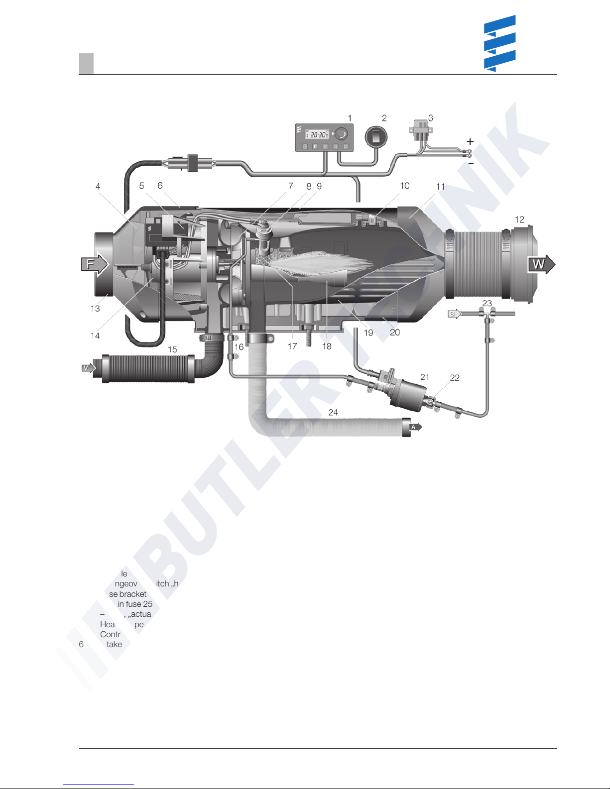
Cutaway view
1 Module timer
2 Changeover switch „heat / ventilate“
3 Fuse bracket
– Main fuse 25 A
– Fuse, „actuation“ 15 A
4 Heater impeller
5 Control box
6 Intake hood
7 Combustion air fan
8 Glow plug
9 Jacket shell, top
10 Combination sensor (overheating and flame sensor)
11 Outlet hood
12 Outflow
13 Safety grille
14 Electrical motor
15 Combustion air intake silencer
16 Fuel connection
17 Combustion chamber
18 Flame pipe
19 Heat exchanger
20 Jacket shell, bottom
21 Metering pump
22 Pot-type strainer
23 T-piece
24 Exhaust pipe
F = Fresh air
W = Hot air
V = Combustion air
A = Exhaust
B = Fuel

6
Function
2
Description of functions
Switching on / starting the heater
When the heater is switched on, the control lamp in the
control unit lights up.
The fan starts up in the fan stage "LOW". The glow plug starts
with a 3 second delay. After approx. 45 seconds the fuel
supply starts and the fuel / air mixture in the combustion
chamber ignites.
The fan switches from fan stage "LOW" to fan stage "MEDIUM". The glow plug is switched off after 165 seconds, when a
stable flame has formed.
The fan switches from fan stage "MEDIUM" to fan stage
"HIGH".
The heater is run at an increased heating capacity of 5.5 kW
(stage "POWER") in order to quickly reach the heater's
operating temperature. If the heater's operating temperature
has been reached, the heating capacity is reduced to 4.8 kW
(stage "HIGH"). The length of time for which the heater is run
with an increased heating output depends on the ambient
temperature.
Control in heating mode
If the intake or ambient temperature set at the control device
(10 °C up to 30 °C) has been reached, the heater switches to
the “LOW“ control level and then continues to run with a low
fan motor speed.
If the heat flow at the “LOW“ control level of 1.2 kW or 2.0 kW
is insufficient, the heater switches to the “MEDIUM“ control
level. The fan continues to run at a low speed. In most cases
the “LOW – MEDIUM – LOW“ control at a low speed will cover
the heating requirements.
If the heat flow at the “MEDIUM“ control level is insufficient, the
heater switches back to the “HIGH“ control level. This in turn
requires the full fan motor speed.
If, in special cases, even less heat flow is required than
supplied by the heater at the “LOW“ control level, the heater
switches to “OFF“.
The fan then continues to run for approx. 4 – 5 minutes and,
only in recirculation mode, constantly ventilates until it is
restarted. The restart takes place at the “MEDIUM“ control
level at a low fan motor speed.
Ventilation mode
If the heater is set to “Ventilation“ at the control element, the
fan runs at maximum speed.
Switching off
When the heater is switched off, the control lamp goes out
and the fuel delivery is switched off.
The fan continues to run for approx. 4 – 5 minutes to cool
down.

7
Function
2
Please note!
Control and safety devices
• If the heater does not ignite within 90 seconds after the fuel
starts to pump, the start is repeated. If the heater still does
not ignite after another 90 seconds of pumping fuel, the
heater is switched off, i.e. the fuel supply is off and the fan
runs on for approx. 4 – 5 minutes. After an unacceptable
number of failed start attempts, the control box is locked.*
• If the flame goes off by itself during operation, the heater is
restarted. If the heater does not ignite within 90 seconds
after the fuel pump has restarted, or ignites and goes off
again within 15 minutes, the heater is switched off, i.e. the
fuel supply is off and the fan runs on for approx. 4 – 5
minutes. This automatic switching off can be cancelled by
briefly switching off and on again. Do not repeat the
switching off / on routine more than twice.
• In the case of overheating, the combined sensor (flame
sensor / overheating sensor) triggers, the fuel feed is
interrupted and the heater switched off. Once the cause of
the overheating has been eliminated, the heater can be restarted by switching off and on again. After an unacceptable
number of failed start attempts, the control box is locked.*
• If the lower or upper voltage limit is reached, the heater is
switched off after 20 seconds.
• The heater will not start if the glow plug or blower motor is
defective or if the electric lead to the metering pump is
interrupted.
• If the combined sensor (flame sensor / overheating sensor)
is defect or the electric lead interrupted, the heater starts up
and is then switched off again during the start phase.
• The speed of the blower motor is continuously monitored. If
the blower motor does not start up or if the speed deviates
by more than 10 %, the heater is switched off after 30 sec.
• When the heater is switched off, the glow plug is switched
on for 40 seconds (after glowing) while the fan runs on, in
order to clean off any combustion residues.
* The lock can be cancelled and the faults read off:
• using the module timer / EasyStart T
• using the radio remote control TP5 / EasyStart R+.
For other controls:
• by connecting the diagnostic unit
• using the customer service program KD2000 / EDiTH.
For operation and fault list, please refer to Page 13 – 24.
Do not repeat the switching off / on routine more than twice.
Forced shut-down during ADR / ADR99 operation
In vehicles for the transport of dangerous goods (e. g. tankers), the heater must be switched off before the truck drives
into a danger area (refinery, petrol station, etc.).
Failure to comply results in the heater automatically switching
off if:
• The vehicle engine is switched off.
• An additional unit is started up (e. g. auxiliary drive for
unloading pump, etc.).
• A vehicle door is opened (ADR99 regulation, only in France).
The fan then continues to run briefly, for max. 40 seconds.
Emergency stop – EMERGENCY OFF
If an emergency stop – EMERGENCY OFF – is necessary
during operation, proceed as follows:
• Switch the heater off at the control unit or
• pull the fuse out or
• disconnect the heater from the battery.

8
AIRTRONIC L – B5 AIRTRONIC L – D5
Air Air
Stage Stage
Power High Medium Low Power High Medium Low
5500 4800 2700 1200 5500 4800 2700 1500
280 275 180 125 280 275 180 125
10 10
0.75 0.65 0.37 0.27 0.66 0.58 0.34 0.19
85 80 30 15 85 80 30 15
< 250 < 250
12 12 / 24
approx. 10 volt and 20 volt respectively
Undervoltage protection trigger time: 20 seconds
approx. 14 volt and approx. 28 volt respectively
Overvoltage protection trigger time: 20 seconds
Petrol – standard commercial quality Diesel fuel – standard commercial
(DIN EN 51600 / DIN EN 228) quality (DIN EN 590)
Heater Control Metering Heater Control Metering
box pump box pump
–40 °C to –40 °C to –40 °C to –40 °C to –40 °C to –40 °C to
+50 °C +75 °C +20 °C +70 °C +75 °C +50 °C
–40 °C to –40 °C to –40 °C to –40 °C to –40 °C to –40 °C to
+85 °C +85 °C +85 °C +85 °C +85 °C +85 °C
+40 °C
Suppression class 5 to DIN EN 55025
approx. 9.3 kg
Possible
Product information
3
Technical data
Heater
Heating medium
Control of the heat flow
Heat flow (watt)
Heater air flow rate without counterpressure (kg/h)
Heater code
Fuel consumption (l/h)
Elect. power consumption (watt) in operation
while starting
Rated voltage (volt)
Operating range
Lower voltage limit: An undervoltage protector
installed in the control box switches off the
heater when the voltage limit is reached.
Upper voltage limit: An overvoltage protector
installed in the control box switches off the
heater when the voltage limit is reached.
Fuel
Permissible ambient temperature
Operation
Storage
Maximum air intake temperature
Interference suppression
Weight
Ventilation mode
Caution!
Safety instructions for technical data!
Failure to comply with the technical data can result in malfunctions.
Provided no limit values are given, the technical data listed is
subject to the tolerances usually applicable to heaters of ±10%
for nominal voltage, ambient temperature 20 °C and reference
altitude Esslingen.
Please note!
9
Test speed for the blower
Heater 12 volt
At 11.3 volt n = 4650 – 7000 U/min
Heater 24 volt
At 23.6 volt n = 4650 – 6500 U/min
Resistance values 12 V 24 V
Glow plug (heat resistance) ca. 0.6 Ω ± 0.04 Ω ca. 2 Ω ± 0.2 Ω
Metering pump 9.5 Ω ± 0.50 Ω 36.0 Ω ± 1.8 Ω
Control device
setpoint value potentiometer 1750 Ω ±30 Ω – 2180 Ω ±80 Ω
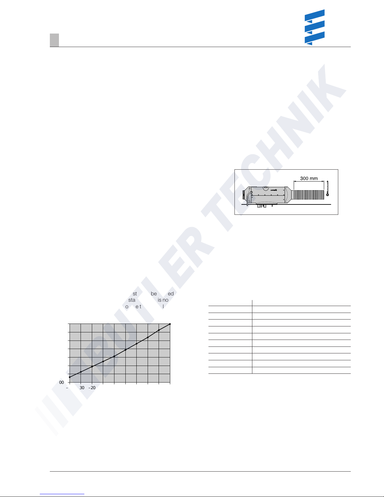
Switching value
Overheating sensor 140 °C – 170 °C
measured in the “POWER” control stage
and at a distance of 300mm
downstream from the hot air outlet.
Exhaust emission specification
CO
2
in exhaust
in control stage “HIGH” 7.5 – 12.5 Vol. %
Smoke spot number < 4
according to Bacharach
Check values
Temperature (°C)
Resistance (ohm)
2200
2000
1800
1600
1400
1200
1000
–40
–20
02040–10
–30
10 30
2400
50
Check “external” temperature sensor
(Order No.: 25 1774 89 03 00)
The “external” temperature sensor test must be carried out
using a digital multimeter. If the resistance value is not the
same as the curve in the diagram or the table of values, replace
the temperature sensor.
Product information
3
Table of values – “external” temperature sensor
Temperature °C Resistance Ω min. max.
016001660
516701730
10 1745 1800
15 1820 1870
20 1895 1950
25 1970 2030
30 2050 2110
35 2130 2190
40 2210 2280
45 2295 2370
10
What to check first in case of faults
• Check
– Fuel in the tank?
– Fuel pipes leaking? (visual check)
– Summer diesel in the fuel pipe?
– Combustion air system or exhaust system damaged or
blocked?
• Electrical components
– Cables, connections damaged?
– Contacts corroded?
– Fuses defective?
– Incorrect wiring? (short circuits, interrupted / broken)
• Measure battery voltage
– Battery voltage < 10.5 volt, the undervoltage protection
of the 12 volt heater has triggered.
– Battery voltage < 21 volt, the undervoltage protection of
the 24 volt heater has triggered.
• Measure voltage supply (Cl 30)
Disconnect the 16-pin connector S1 / B1 and measure the
voltage applied at connector B1 between chamber 1 (cable
2.52 rt) and chamber 10 (cable 2.52 br).
If it differs from the battery voltage, check the fuses, the
supply cables, the negative connection and the positive
support point on the battery for voltage drop (corrosion /
interruption).
• Check switch-on signal
Disconnect the 16-pin connector S1 / B1 and then switch on
the heater at the control unit.
Check whether voltage is applied in the connector B1
between chamber 4 (cable 0.52 ge) and chamber 10 (cable
2.52 br).
If no voltage is measured, then check the supply cable (cable
0.52 ge), the 5 A fuse (item 2.7.1 in the circuit diagram) and
the control unit.
• Check control unit
Disconnect the connector at the control unit, jumper between the red 0.52 cable and the yellow 0.52 cable.
If a voltage is measured in connector B1 between chamber
4 (cable 0.52 ge) and chamber 10 (cable 2.52 br), then
replace the control unit.
Troubleshooting
4
11
Troubleshooting
4
Overview of the individual test equipment
and control units
The electronic control box can store up to 5 errors, which can
be read out and displayed. The following test equipment can
be used to query the fault memory in the control box and if
necessary to delete the control box locking:
Test equipment Order No.:
• Testing device
for the control device 22 1509 89 00 00
• Diagnostic unit 22 1529 89 00 00
additionally required:
Adapter cable 22 1000 31 86 00
• EDiTH Customer service program 22 1532 89 00 00
– Basic adapter with software 22 1532 89 00 00
Also required:
AIRTRONIC extension 22 1537 89 00 00
– ISO adapter 22 1524 89 00 00
Also required:
Adapter cable 22 1000 31 86 00
If a diagnostics cable is connected, the following control units
can also be used:
Control units Order No.:
• Module timer 22 1000 30 34 00
• TP5 radio remote control 22 1000 32 01 00
• EasyStart T 22 1000 32 88 00
• EasyStart R+ 22 1000 32 80 00
If the fault memory cannot be read out, check the diagnostics
cable for correct laying and possible damage.
Locking the control box
The control box is locked if the following faults occur:
• Too many attempted starts
If the heater carries out several failed start attempts in
succession – fault code 050 is displayed –> the control
box is locked.
• Overheating
If the heater overheats several times in succession –
fault code 015 is displayed –> the control box is
locked.
Cancel the control box lock
Cancellation of the control box lock depends on the
appropriate test equipment and is described on
pages 13 – 19.
Please note!

12
Troubleshooting
4
Caution!
Operating voltage safety information!
Ensure you use the correct operating voltage, otherwise the
connected components can be severely damaged.
Check control unit
Order No. for the testing device – control unit –
22 1509 89 00 00
Before the test
Connect the correct operating voltage (12 or 24 volt) to the
testing device, with plus at the red connector socket and
minus at the blue connector socket.
• Disconnect socket from the control unit.
• Connect cable loom from testing device with the control unit.
• Set the rotary knob of the control unit to „Heat“, the
corresponding red LED in the testing device must light up.
• Set control unit to „0“, then press the „LED – red“ button, the
red control lamp in the control unit must light up.
• Set control unit to „Heat“, then press the „LED – green“
button, corresponding red control lamp in the testing device
and the green control lamp in the control unit must light up.
Check the setpoint potentiometer of the control unit
Set the “Temperature sensor / Potentiometer“ switch in the
testing device to the “Potentiometer“ setting and slowly turn
the rotary knob of the control unit.
The green LED – temperature sensor / potentiometer must
light up continuously.
In case of a fault, replace the control unit.
––– OFF
Heat
13
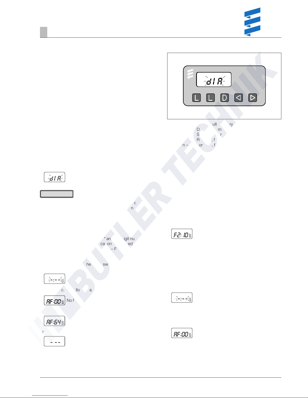
Display of the fault memory F1 – F5 or F5 – F1
• The heater is switched on.
• Press the buttons e and f once or several times to
display the individual fault memory positions, in ascending or
descending order.
Display is as follows:
e.g. fault memory 2 / fault code 10
Only the fault memory positions with an error code assigned to
them are displayed.
Delete fault memory
• Correct cause of fault.
• Press button D –> the heater is switched on.
• Press both L keys simultaneously until the following
appears in the display:
Display flashes, heater symbol does not flash
If all the fault memory positions have been deleted the most
recent fault is displayed. The most recent fault is not reset to
00 until the heater is restarted.
Display is as follows:
Heater has no malfunction
If a new, most recent fault exists it is displayed.
Connect diagnostic unit
• Disconnect the 16-pin connector of the heater’s cable
harness and connect the adapter cable.
• The connect the diagnostic unit to the adapter cable.
After the adapter cable and diagnostic unit have been
connected the following appears in the display.
It is very important to always install in the given order.
Fault code, fault description, cause / remedial action are
described on Pages 20 to 24.
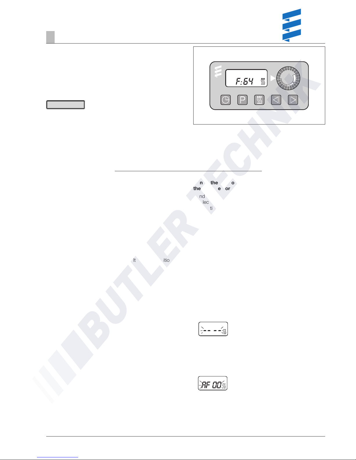
Enquire fault memory
The current fault is displayed as „AF“ and a 2-digit number and
is always written in the memory location F1. Preceding faults
are moved to the memory locations F2 – F5, if necessary the
content of F5 is overwritten.
• Press button D –> the heater is switched on.
Display is as follows:
• After 8 sec. the following appears in the display:
No fault
or
e.g. current fault / fault code 64
or
Fault diagnosis not possible
Possible causes:
– Adapter cable is not properly connected.
– Control box is defective or not diagnosable
(not a universal control box).
Troubleshooting
4
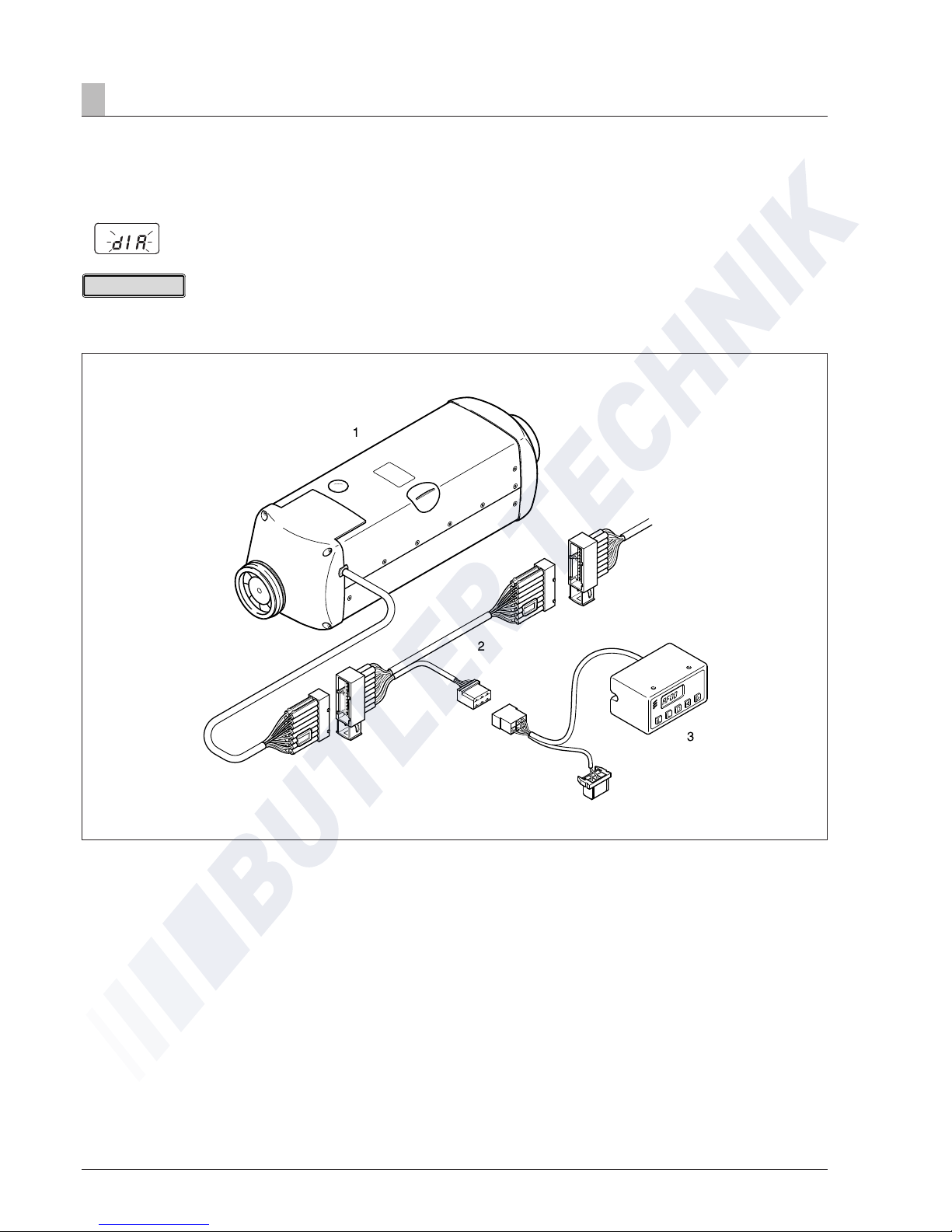
Fault diagnosis using the diagnostic unit
Diagnostic unit
Order No. 22 1529 89 00 00
An adapter cable is required to connect the diagnostic unit.
Adapter cable
Order No. 22 1000 31 86 00
l
button – Delete fault memory
l
button – Delete fault memory
d
button – Switch heater on / off, request diagnosis
e
button – Reverse, fault F5 – F1, AF
f
button – Forward, fault AF, F1 – F5
Please note!
14
Troubleshooting
4
Cancel the control box lock
• Delete the fault memory as described and switch off the
heater using the d button.
• The control box lock is cancelled and the diagnosis closed.
Display is as follows:
Please note!
Not only the defective component, but also a defective current
circuit results in a fault being displayed.
1 Heater
2 Adapter cable
3 Diagnostic unit
15
Troubleshooting
4
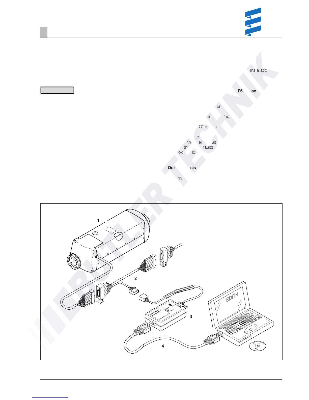
EDiTH customer service program
with ISO adapter
Order No. 22 1524 89 00 00
An additional adapter cable is required to connect the ISO
adapter (Order No.: 22 1000 31 86 00).
• It is very important to always install in the given order.
• Not only the defective component, but also a defective
current circuit results in a fault being displayed.
• Fault code, fault description, cause / remedial action are
described on Pages 20 – 24.
• The scope of supply does not include the EDiTH customer
service software; this must be downloaded from the service
portal.
Connect ISO adapter
• Disconnect the heater’s cable harness.
• Connect the adapter cable to the cable harness – as shown
in the sketch.
• Connect the adapter cable to the ISO adapter.
• Connect the SUB-D connection cable with the PC and the
ISO adapter.
Installing the software on your PC
• Double-click the „setup.exe“ file to start the installation and
following the SETUP program instructions.
Enquire / delete fault memory F1 – F5 or cancel the
control box lock
• Start the software on your PC:
– On the desktop
–> Double click the „EDiTH“ icon.
– Select heater type.
– Press the „GO“ button.
• Delete fault memory or cancel the control box lock:
– Press the „Delete fault memory“ button
—> the stored faults F1 – F5 are deleted and the control
box is unlocked.
Quit diagnosis
• Press the „STOP“ button –> fault memory enquiry is ended.
Please note!
1 Heater
2 Adapter cable
3 ISO adapter
4 SUB-D connection cable
16
Troubleshooting
4
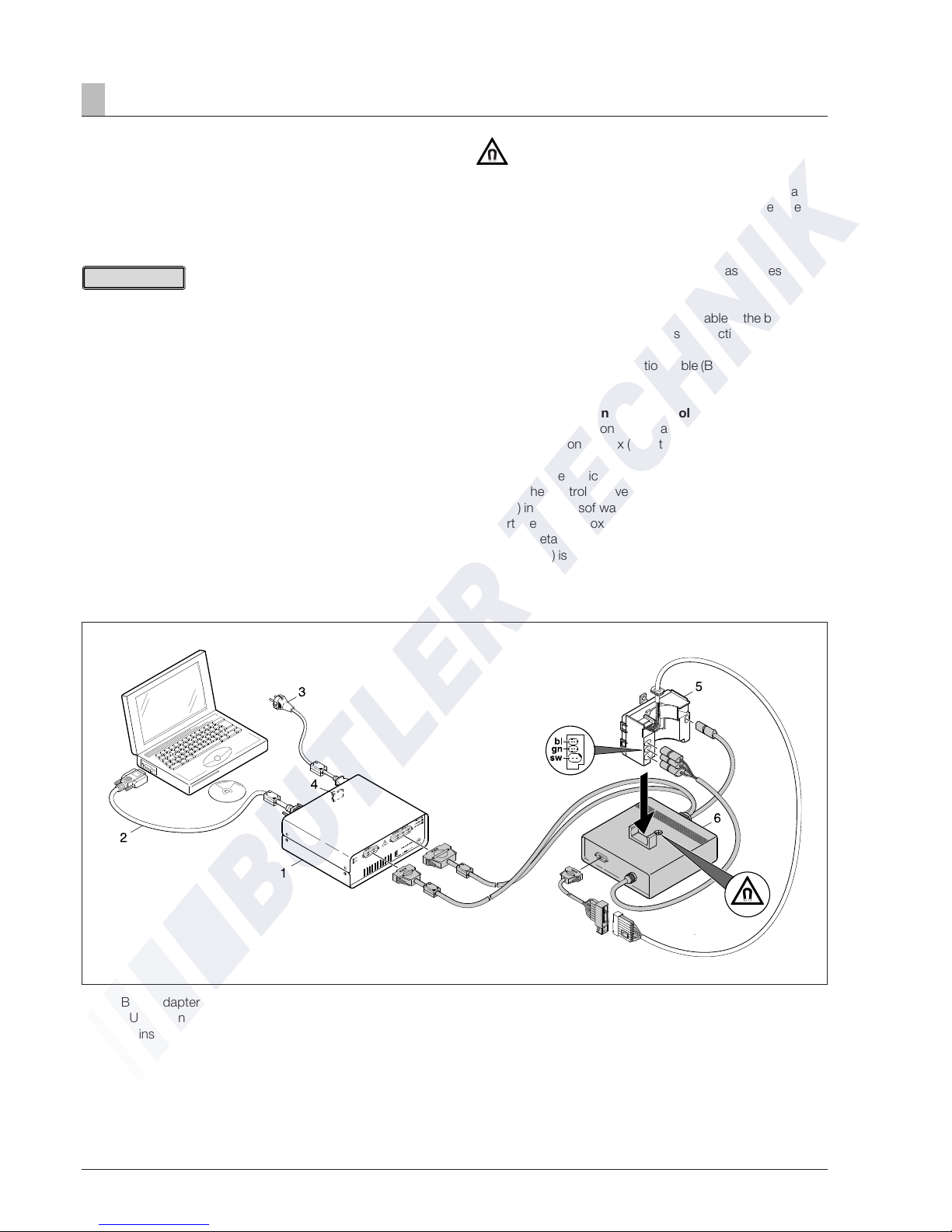
Caution!
Magnetic field!
During the test operation a magnetic field develops at the
adapter. Therefore, do not place any objects such as data
media, credit cards, etc. on the adapter or in its immediate
vicinity.
1 Basic adapter
2 SUB-D connection cable
3 Mains connection
4 Mains switch
5 Control box
6 Adapter
Cable colours
sw = black
gn = green
bl = blue
EDiTH customer service program with
basic adapter
EDiTH basic adapter
(Order No.: 22 1532 89 00 00)
An additional extension is required to check the control box
(Order No.: 22 1537 89 00 00).
• It is important to always follow the precise connection order
as given below!
• The Hall sensor integrated in the control box can only be
properly tested in the control box is correctly placed on the
extension.
• Only push or pull on the connectors, not on the cables!
• Only use the network cable and RS232 cable with snap
ferrites included in the scope of supply. Use original accessories with snap ferrites only to connect the test equipment.
• Not only the defective component, but also a defective
current circuit results in a fault being displayed.
• Fault code, fault description, cause / remedial action are
described on pages 20 – 24.
Connect basic adapter
• Start computer and wait until the system has successfully
booted.
• Start PC software.
• Insert the unit connector of the mains cable in the basic
adapter (A) and connect the mains connection (C) to the
mains.
• Connect the SUB-D connection cable (B) with the PC and
basic adapter (A).
Connect extension and test control box
• Connect the extension to the basic adapter (A).
• Connect the control box (E) to the extension and the
adapter (F).
• Switch on the basic adapter (A) at the mains switch (D).
• Select the control box version and operating voltage (12 V /
24 V) in the PC software.
• Start the control box test with the PC software.
A more detailed description of how to operate the basic
adapters (A) is given in the EDiTH online help.
Please note!
17
Troubleshooting
4
Module timer
(Order No.: 22 1000 30 34 00)
The current fault is displayed as “AF” and is always written in
memory position F1.
Preceding faults are moved to the memory locations F2 – F5, if
necessary the contents of memory position F5 is overwritten.
• Not only the defective component, but also a defective
current circuit results in a fault being displayed.
• Fault code, fault description, cause / remedial action are
described on pages 20 – 24.
Query fault memory F1 – F5
Condition:
The heater is switched off.
• Press c key –> the heater is switched on.
• Press a key and keep pressed,
then press p key within 2 seconds.
Display is as follows:
AF = current fault
3 digit number = fault code
c
flashes.
• Press f key once or several times, fault memory positions
F1 – F5 are displayed.
Cancel the control box lock and simultaneously delete
the fault memory
Condition:
An electrical connection exists from terminal 15 (ignition) to the
module timer, 12-pin connector, chamber 10.
• Press c key
Display is as follows:
the current fault F15 or F50.
• Press button a, keep it depressed and then press button
p
within 2 seconds.
The module timer is now in the “Query fault memory”
program.
• Switch off ignition (terminal 15).
• Simultaneously press button a and button p, in addition,
switch on the ignition (terminal 15) and wait until the following
appears in the display.
After ignition “ON” the following appears in the display:
Display flashes,
Heater symbol does not flash
• Switch the heater off and on –> the control box is unlocked,
the heater restarts.
After switching the heater off and on and renewed query of
the fault memory, the following appears in the display:
Display flashes,
Heater symbol does not flash
a
–Time
p
–Preset
c
–Heat
e
–Reverse
f
–Forward
Please note!
 Loading...