

Page 1

*
Mini
Controller
AIRTRONIC
Operating
Instructions I Mounting
Instructions
@
Eberspacher ®
~
Temperature preselection control knob
J. Eberspacher
GmbH & Co.
KG
Ebelrsrillict"m,tr. 24
• Left-hand end stop approx.
8°C
- small amount of heat
• Right hand end stop approx.
34°C
- large amount of heal
[)ll]
Heater
III
Red
LED
- Operation check for heater
SWitch
off (not
in
combination with mini clock)
If]
Ventilator
www.eberspaecher.com
• Blue
LED
- operation check for ventilator
Order
No.
22
1000 32 07 00
The
mini controller enables
you
to
set the heater installed
in
the vehicle to the temperature you require.
You
can either use the mini controller alone or
in
combination
with the mini-clock.
Stand-alone mini-controller
Start heater - heating mode:
Use
the
[lllJ
button to start the heater
in
heating mode
(continuous operation).
You
can adjust the required temperature
with the
control knob
~.
If
the heater
is
in
heating mode, the red
LED
lights up as a check.
Start
heater
- ventilation
m~:
Use
the·~
button to start the
heate~lM~entiiatlon
mode
(continuous operation). The control knob
IQl
has
no
function
in
ventilation mode.
If
the heater
is
in
ventilation mode, the blue
LED
lights up as a check.
Switch off heater:
Use
the
[Q]
button to switch off the heater. Heater or ventilation
mode
is
terminated and the corresponding
LED
goes out.
Heating mode
is
terminated with after run.
Mini controller combined with the mini-clock
If
the mini-controller
is
installed
in
a vehicle together with the
mini-clock, the
mini-clock takes over the switch
on
/ off function.
In
addition,
it
is now possible to program preset times. Informa-
tion about programming is given
in
the enclosed operating and
installation instructions for the mini-clock.
Note:
The
[Q]
button has no function when the controller is used
in
combination with the mini-clock.
You
can only switch the heater
on
/ off using the mini-clock.
a)
Heater
is
switched off (mini-clock inactive)
If
the heater
is
switched off,
it
is
possible to pre-select the heater
or
ventilation modes using the mini-controller.
The
heater itself
can only be switched
on
via the mini-clock.
Set preselected heater mode at the mini-controller:
Use
the
[lI\J
button to select heater mode - the preselection
is
saved.
You
can adjust the set temperature required using the
temperature-preset controller.
The
red
LED
lights up for approx.
3 secs
as
confirmation. However the heater
is
not started.
Subject
to
change
Set preselected ventilation mode at the mini-controller:
Use the
~
button
to
select ventilation mode - the preselection
is
saved. The temperature-preset controller has
no
function
in
ventilation mode.
The
blue
LED
lights up for approx. 3 secs
as
confirmation. However the heater
is
not started.
b)
Heater
is
switched
on
(mini-clock active)
The
ON
/ OFF button
is
used to switch
on
the saved mode
(heater / ventilation - preselected by the mini-controller). If the
heater
is
in
Heater mode, the red
LED
lights up, in
v\lll,tilla!l()1'\
mode the blue
LED
lights up
as
a check.
Change between
heating aflj:tV!1ft118_tftlM
.....
tlll!.~
the mini-controller:
Use the
[lI\J
button
to
change
to
heater mode.
The set temperature required can be adjusted using the temperature preset controller.
If
the heater
is
in
heater mode the
red
LED
lights up
as
a check.
The
preset operating mode
is
updated.
Use the ~ button to change
to
ventilation mode.
The temperature-preset controller has
no
function
in
ventilation
mode.
If
the heater
is
in
ventilation mode, the blue
LED
lights up
as
a check.
The
preselected operating mode
is
updated.
Heater mode
is
terminated with after run.
Change the required set temperature using the mini-controller:
The
required temperature can be adjusted at any time during
heating mode using the temperature-preset
controller.
Emergency operation error when presetting the operating mode:
The preset operating mode was not able
to
be saved.
The red
LED
flashes for approx. 10 secs. The mini-controller
Emergency opflrallon
reversed by carrying out the preselection process again
or
using
a voltage reset
(pullout
the fuse),
If
the heater
is
switched
on
by the mini-clock
in
emergency
mode, the red
LED
lights up and flashes. The heater
is
in
heater
mode with preset set value,
It
is
not possible to change the operating mode
in
emergency
mode. The heater can only be switched off via the mini-clock.
Page 2
-----------------------------~
.•
~--~
.•
-~~~~.-~.-.~-------~
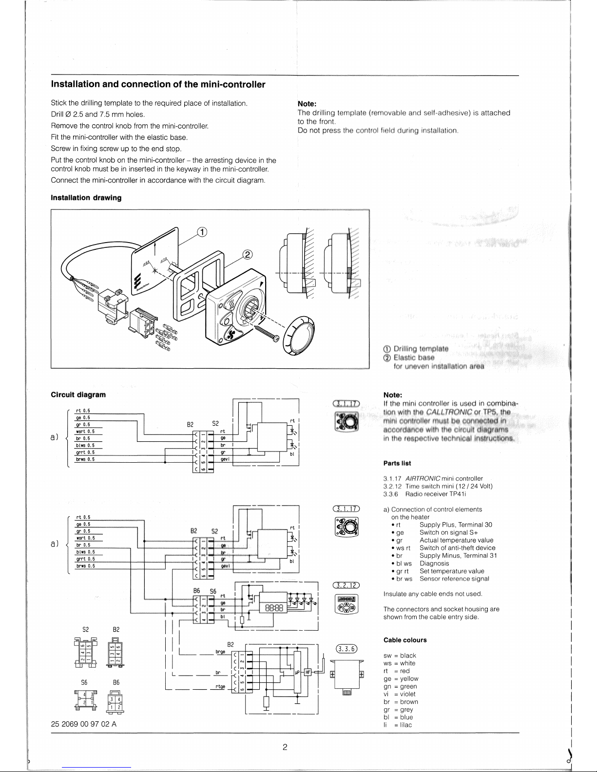
Installation and connection
of
the mini-controller
Note:
Stick the drilling template
to
the required place of installation.
Drilll2l
2.5 and 7.5 mm holes.
Remove the control knob from the mini-controller.
Fit
the mini-controller with the elastic base.
Screw
in
fixing screw up to the end stop.
The
drilling
to the front.
Do not
press the
Put the control knob
on
the mini-controller - the arresting device
in
the
control knob must be
in
inserted
in
the keyway
in
the mini-controller.
Connect
the
mini-controller
in
accordance with the circuit diagram.
Installation drawing
Circuit diagram
rt
0.5
go
0.5
gr
0.5
wart
0.5
a)
br
0.5
a)
---
blw. 0.5
grrt
0.5
brws
0.5
rt
0.5
ge
0.5
gr 0.5
wsrt
0.5
br
0.5
blw80.5
grrt
0.5
brws
0.5
52
56
uru=r
~
82
86
m
J1:Ql
252069009702
A
in-----i
I I
l~.~-~~I
I
L-.J--<I---'
___
~
I
l
_____
J
2
a:r.1D
~
o
self~adhesive)
is attached
Parts list
7 AJRTRONIC mini controller
switch mini
(12/
24 Volt)
Rnd;o receiver
TP41
i
a) Connection of control elements
on
the heater
•
rt
Supply Plus, Terminal 30
•
ge Switch
on
signal S+
•
gr Actual temperature value
•
ws
rt
Switch of anti-theft device
• br Supply Minus, Terminal
31
•
bl
ws
Diagnosis
• gr rt Set temperature value
• br
Insulate any cable ends not used.
The connectors and socket housing are
shown from the cable entry side.
Cable colours
sw = black
ws
= white
rt = red
ge = yellow
gn
= green
vi
= violet
br
= brown
gr
= grey
bl
= blue
= lilac
 Loading...