

Page 1
ASSEMBLY AND INSTALLATION
INSTRUCTIONS
WARNING: BE SURE TO SHUT OFF POWER AT THE MAIN FUSE OR CIRCUIT
BREAKER BOX BEFORE INSTALLING OR SERVICING THIS FIXTURE.
NOTE: 1. Before installing, consult local electrical codes for wiring and grounding requirements.
2. READ AND SAVE THESE INSTRUCTIONS.
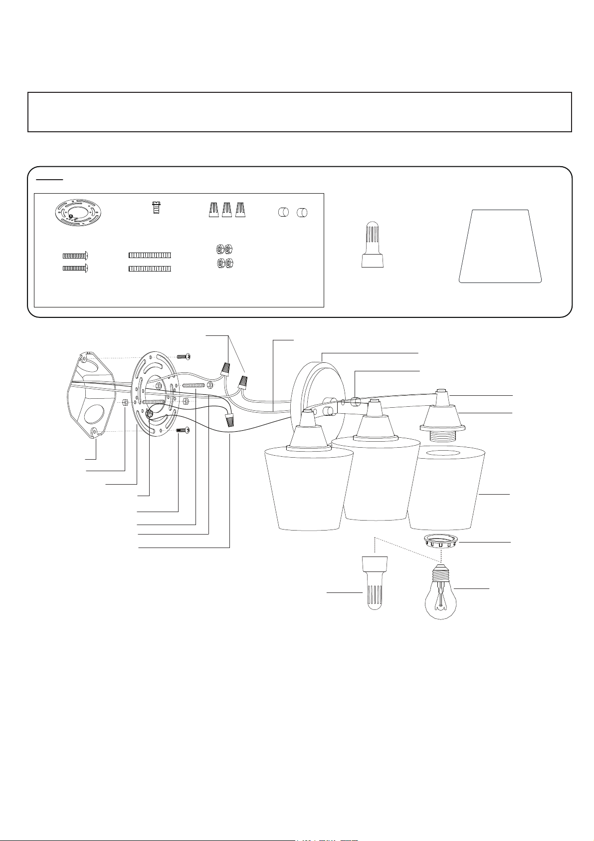
Parts:
Mounting Plate (A)
Mounting Screw (B)
Outlet Box
Lock Nut (F)
Mounting Plate (A)
Green Grounding Screw (C)
Mounting Screw (B)
Headless Screw(D)
House Grounding Wire
Fixture Grounding Wire
Green Grounding
Screw (C)
Headless Screw(D)
Wire Nut (E)
Wire Nut (E)
Lock Nut (F)
Ball Nut (G)
Fixture Wire
Socket Fixer (H) (X1)
Glass Shade (I) (X3)
Back Plate
Ball Nut (G)
Fixture
Glass bracket
Glass Shade (I)
Socket Ring
Socket Fixer (H)
Bulb Type A Max.100W
(not included)
1. Thread two headless screws through the mounting plate, then secure them with four lock nuts (two
on each side of the mounting plate). Adjust the length of the headless screws if necessary.
Note: Make sure that the headless screws are lined up horizontally, to ensure that the fixture will be
level.
2. Attach the mounting plate to the outlet box by using two mounting screws.
3. Pull out the outlet wires and the house grounding wire from the outlet box. Make wire connections
by using the wire nuts:
---Connect the black (hot) wire from the fixture to the black (hot) wire from the power source.
---Connect the white (neutral) wire from the fixture to the white (neutral) wire from the power source.
Page 2
---Attach the fixture grounding wire to the mounting plate with the green grounding screw. Then
connect it to the house grounding wire with a wire nut.
Carefully put the wires back into the outlet box.
4. Attach the back plate to the mounting plate by inserting the headless screws, then secure it with
two ball nuts.
5. Attach the glass shades onto the glass brackets, secure it with socket rings, using supplied socket
fixer.
6. Install bulbs (not included). See relamping label at socket area or packaging for maximum
allowed wattage.
7. Turn on the power at the main fuse or circuit breaker box.
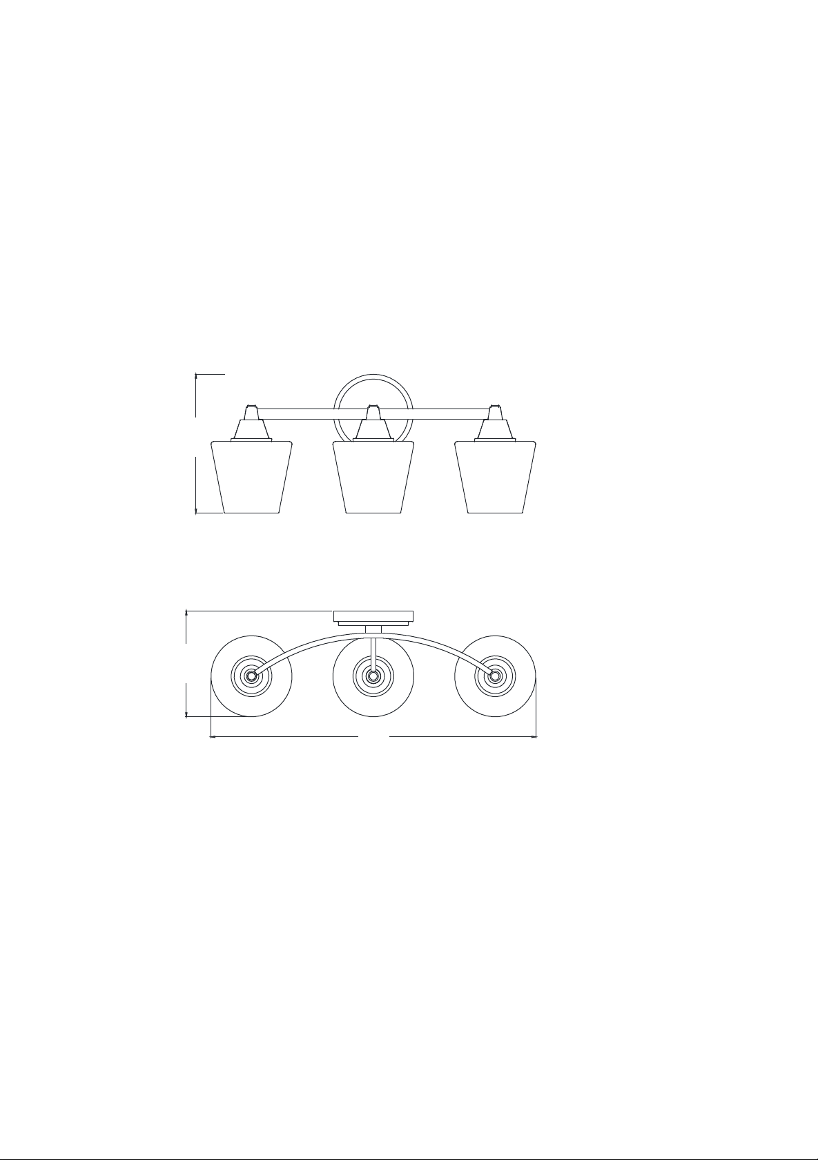
B
C
A: 20"
B: 8-1/2"
C: 6-1/4"
A
 Loading...