

THIS MANUAL CONTAINS TECHNICAL INFORMATION FOR
THE PS2248-HV SERIES POWER SUPPLY.
REVISION: FEBRUARY 2017
pn 888-2248-001
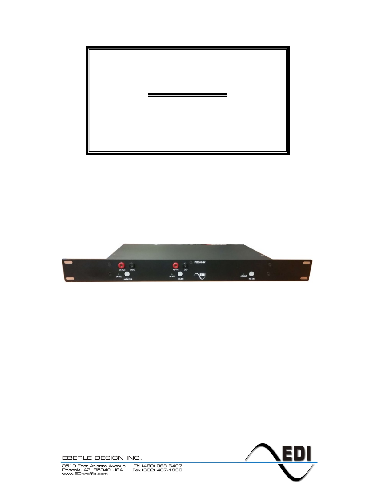
PS2248-HV
High Efficiency ATC Cabinet Power Supply
Operations Manual

THE PS2248 SERIES POWER SUPPLY IS DESIGNED AND MANUFACTURED IN THE
USA BY EBERLE DESIGN INC., PHOENIX, ARIZONA
EDI IS CERTIFIED TO ISO 9001:2008 QUALITY SYSTEMS STANDARDS.
INFORMATION CONTAINED HEREIN IS PROPRIETARY TECHNICAL INFORMATION
OF EBERLE DESIGN INC. PUBLICATION, REPRODUCTION OR USE IN WHOLE OR
PART IS NOT PERMITTED EXCEPT UNDER TERMS AGREED UPON IN WRITING.
© COPYRIGHT 2017 EDI

PS2248-HV Cabinet Power Supply
Operations Manual
Eberle Design Inc. Page 1
1.1 OVERVIEW
The PS2248-HV Cabinet Power Supply series is a 1U high 19” rack mounted high
efficiency switching power supply for the Advanced Transportation Controller Cabinet
(ATCC). The PS2248-HV model provides a main 48VDC output intended for field signal
loads, and an isolated 24VDC output for internal cabinet peripherals. The PS2248-HV
Cabinet Power Supply is intended to power ATC Cabinets operating with DC powered low
voltage (48 VDC) Output Assemblies (LV).
The PS2248-HV series provides output regulation across changes in AC Line voltage and
output load over the full NEMA operating temperature range of -34C to +74C. Power Factor
Correction is also provided reducing peak AC Line input current and associated stress on
wiring. The outputs are protected against voltage transients by a 1500 Watt suppressor.
1.2 INDICATORS
A green LED indicator is provided to display AC Line input status and fuse integrity.
Separate green LED indicators are provided to display output status and fuse integrity for
each DC output.
1.3 SPECIFICATIONS
1.3.1 AC POWER REQUIREMENTS
AC Operating Voltage ..................................................................................... 90 to 270 Vac
AC Operating Frequency .................................................................................. 45 to 65 Hz
Maximum Input Current (85 Vac) ...............................................................................6 Amps
Power Factor (120 Vac at full load) ................................................................................. 0.98
Maximum Input Surge ............................................................................................ 50 Amps
1.3.2 DC OUTPUTS
Total DC Output Power (**see Table below) ......................................................... 450 watts
48VDC Output Voltage .............................................................................. 48 Vdc +/- 2 Vdc
48VDC Output Current Maximum ............................................................................... 8 Amp
24VDC Output Voltage .............................................................................. 24 Vdc +/- 2 Vdc
24VDC Output Current Maximum ..............................................................................5 Amps
DC Output Ripple Maximum ................................................................................ 500 mVpp
Note: Ripple is measured at 20MHz of bandwidth using a 12" twisted pair-wire
terminated with a 0.1uf & 47uf capacitor.
Maximum Power-up time (110 Vac, -34
o
C) ................................................1000 milliseconds
Minimum Holdup Time (450 Watts DC Output Load) ................................... 50 milliseconds
1.3.3 MECHANICAL
Rack Height .................................................................................................. (1U) 1.7 inches
Rack Width ........................................................................................................ 19.0 inches
Depth ................................................................................................................ 7.40 inches
**PS2248 DC Power Rating
The total DC output power must be limited to 450 watts total.
The DC output power is calculated as:
P = 48*I
48
+ 24*I24
Where Ixx is the maximum output current supplied from each
DC output; 48V and 24V.

PS2248-HV Cabinet Power Supply
Operations Manual
Eberle Design Inc. Page 2
1.3.4 ENVIRONMENTAL
Operating Temperature Range ........................................................................ -34 to +74
o
C
Storage Temperature Range ........................................................................... -45 to +85
o
C
Humidity (non-condensing) ....................................................................... 0 to 95% Relative
1.4 DC CONNECTOR
The output connector is a Phoenix Contact #1825161 and mates with a Phoenix Contact
#1825352 or equivalent. Pin #1 is the right most pin when viewed from the rear of the
supply.
Pin
Function
1
+48VDC
2
48VDC Ground**
3
+24VDC
4
Reserved
5
24VDC Ground
6
Chassis Ground
**NOTE
The 48 VDC output is electrically isolated from the AC Line
input and the 24VDC output. The 48VDC Ground (pin #2) must
be connected within the cabinet to the Cabinet Monitor Unit
(CMUip-2212-LV) MAINS GROUND pin B32.
 Loading...