

Page 1
MMU-16LE Series
SmartMonitor
NEMA TS-2
Enhanced Malfunction Management Unit
Operations Manual
THIS MANUAL CONTAINS TECHNICAL INFORMATION FOR THE MMU-16LE and
MMU16LEip SmartMonitor
®
SERIES MALFUNCTION MANAGEMENT UNIT.
REVISION: APRIL 2012
pn 888-0116-001
®
Page 2

THE MMU-16LE SERIES IS DESIGNED AND MANUFACTURED IN THE USA BY
AN ISO 9001 :2008 REGISTERED COMPANY
INFORMATION CONTAINED HEREIN IS PROPRIETARY TECHNICAL INFORMATION
OF EBERLE DESIGN INC. PUBLICATION, REPRODUCTION OR USE IN WHOLE OR
PART IS NOT PERMITTED EXCEPT UNDER TERMS AGREED UPON IN WRITING.
EBERLE DESIGN INC.
PHOENIX, ARIZONA
© COPYRIGHT 2004-2012 EDI
Canadian Patent No. 2,574,101
U.S. Pat. No. 7,246,037
MAINTENANCE NOTE
THIS EBERLE DESIGN INC. MALFUNCTION MANAGEMENT UNIT
HAS BEEN CAREFULLY INSPECTED AND TESTED TO ENSURE
PROPER OPERATION. IT IS RECOMMENDED THAT THE
MALFUNCTION MANAGEMENT UNIT BE TESTED AT LEAST
ANNUALLY TO ENSURE PROPER OPE RATION AND COMPLIANCE
WITH FA C TOR Y SP EC IFICATIONS.
.
Page 3

Table of Contents
Section 1 General.................................................................................................................... 1
1.1 Description.................................................................................................................... 1
1.2 Advanced Feature Overview ....................................................................................... 1
1.2.1 Liquid Crystal Status and Field Display ............................................................. 1
1.2.2 Menu Driven Operation ...................................................................................... 1
1.2.3 Context Sensitive Help System ......................................................................... 1
1.2.3.1 Set-up Wizard ........................................................................................... 1
1.2.3.2 Diagnostic Wizard ..................................................................................... 1
1.2.4 Pr ogram Card M em ory ....................................................................................... 2
1.2.5 RMS Voltage Reporting ..................................................................................... 2
1.2.6 ECcom Software Interface ................................................................................. 2
1.2.7 Nema TS-1 Operation With SDLC Mode .......................................................... 2
1.2.8 Flashing Yellow Arrow (FYA) Protected-Permis s ive Mo vem ent ...................... 2
1.2.9 Five Secti on Arr ow Su ppression Protected-Permissive Movement (PPLT5) .. 3
1.3 General ......................................................................................................................... 3
1.4 Field Signal Terminals ................................................................................................. 4
1.4.1 LEDguard® LED Field Signal Sensing ............................................................... 4
1.4.2 Type Select Input ............................................................................................... 4
1.4.2.1 Type 12 With SDLC Mode........................................................................ 5
1.4.2.2 Force T ype 16 M od e ................................................................................ 6
Section 2 Standard Functions ............................................................................................... 7
2.1 Conflict Monitoring ....................................................................................................... 7
2.2 Red Fail M onit or i n g ...................................................................................................... 7
2.2.1 Red Enable Input ................................................................................................ 7
2.2.2 Walk Disable Option ........................................................................................... 7
2.3 Voltage Monitoring ....................................................................................................... 8
2.3.1 +24Vdc Supply Monitoring ................................................................................. 8
2.3.1.1 +24Vdc Monitor Inhibit Input .................................................................... 8
2.3.1.2 +24Vdc Monitor Latch Input ..................................................................... 8
2.3.1.3 +24Vdc M on it or II 12V dc M od e ................................................................ 8
2.3.2 Controller Voltage / Fault Monitor Input ............................................................. 8
2.3.2.1 CVM Monitor Latch Input.......................................................................... 9
2.3.2.2 CVM Log Disable ...................................................................................... 9
2.4 Local Flash Status Input .............................................................................................. 9
2.5 Minimum Yellow Change / Red Clearance Monitoring ............................................... 9
2.5.1 Mini m u m Y ell ow Change Interval ...................................................................... 9
2.5.1.1 Minimum Yellow Clearance Disable ........................................................ 9
2.5.2 Minimum Yellow Plus Red Interval .................................................................... 9
2.5.2.1 Minimum Yellow Plus Red Clearance Disable ...................................... 10
2.6 MMU Power Failure Detection ................................................................................... 10
2.7 Port 1 Communications.............................................................................................. 10
2.7.1 Port 1 Timeout .................................................................................................. 11
2.7.2 Port 1 Disable Input .......................................................................................... 11
2.8 Type 129 Response Frame ....................................................................................... 11
2.9 Output Relay Recovery .............................................................................................. 12
2.10 Internal Diagnostics ................................................................................................. 12
2.10.1 Memory Diagnostics ....................................................................................... 12
2.10.2 Mic roproc essor Monitor.................................................................................. 12
2.10.3 Internal Hardware Monitor ............................................................................. 12
Section 3 Enhanced Features ............................................................................................. 13
3.1 Har d w ar e F eat ures .................................................................................................... 13
3.2 Dual In dication M on itoring ......................................................................................... 13
3.2.1 Walk Disable Option ......................................................................................... 14
.
Page 4

3.3 External Watchdog Monitoring .................................................................................. 14
3.4 Program Card Absent Indication ............................................................................... 14
3.5 Reset Input Detection ................................................................................................ 14
3.6 Display LED Test ....................................................................................................... 14
3.7 Recurrent Pulse Detection ......................................................................................... 15
3.8 Type Fault................................................................................................................... 15
3.9 Field Check Monitoring .............................................................................................. 16
3.9.1 Field Check Fault ............................................................................................. 16
3.9.2 Field Check Status ........................................................................................... 16
3.10 Diagnostic Wizard .................................................................................................... 17
3.11 Flashing Yellow Arrow Protected-Permissive Monitoring (FYA) ............................ 18
3.11.1 Basic FYA MODE ........................................................................................... 18
3.11.2 Compact FYAc MODE ................................................................................... 19
3.11.2.1 FYAc Type 16 Mode ............................................................................. 19
3.11.2.2 FYAc Type 12 Mode ............................................................................. 20
3.11.3 FYA Channel Assignment Diagrams ............................................................. 21
3.12 Five Section Arrow Suppression Protected-Permissive Monitoring (PPLT5) ........ 22
3.12.1 Basic PPLT5 Arrow Suppression Mode ........................................................ 22
3.12.2 PPLT5 Arrow Suppression Channel Assignment Diagrams......................... 24
Section 4 ECcom Interface .................................................................................................. 25
4.1 EDI ECcom Monitor Reports ..................................................................................... 25
4.1.1 General Data .................................................................................................... 25
4.1.2 Current Status (S) ............................................................................................ 25
4.1.3 Pr evious Fault (PF) Event Log ......................................................................... 25
4.1.4 AC Line (AC) Event Log ................................................................................... 25
4.1.5 Manual Reset (MR) Event Log ........................................................................ 26
4.1.6 Configuration (CF) Event Log .......................................................................... 26
4.1.7 Si gn al S equence E ven t L og............................................................................. 26
4.2 Configuration Programming ....................................................................................... 26
4.2.1 ECcom Configurati on Set-up Wizard............................................................... 26
4.3 Ethernet LAN Port ...................................................................................................... 26
Section 5 Menu Operation ................................................................................................... 27
5.1 Main Status Menu ...................................................................................................... 27
5.2 Top Lev el M en u ......................................................................................................... 27
5.2.1 St atus ................................................................................................................ 27
5.2.2 Men u ................................................................................................................. 28
5.2.2.1 View Logs ............................................................................................... 28
5.2.2.2 View and Set Configuration .................................................................... 28
5.2.2.3 Set-up Wizard ......................................................................................... 28
5.2.2.4 Clear Logs ............................................................................................... 29
5.2.2.5 Set Clock ................................................................................................. 29
Section 6 Installation ............................................................................................................ 30
6.1 General ....................................................................................................................... 30
6.2 Program Card Programming...................................................................................... 30
6.2.1 Per mis s i ve C h an n el Pr ogram mi ng .................................................................. 30
6.2.2 Minimum Flash Time Programming ................................................................. 31
6.2.3 Minimum Yellow Change Disable Programming ............................................. 31
6.2.4 Voltage Monitor Latch Programming ............................................................... 31
6.3 Enhanced Function Programming ............................................................................. 32
6.3.1 Field Check Enable Programming ................................................................... 32
6.3.2 Dual Indication Enable Programming .............................................................. 32
6.3.3 Red Fail Enable Programming ......................................................................... 32
6.3.4 Unit Option Programming................................................................................. 33
6.3.4.1 Recurrent Pulse Option .......................................................................... 33
6.3.4.2 Walk Disable Option ............................................................................... 33
6.3.4.3 Log CVM FAULTS Option ...................................................................... 33
.
Page 5

6.3.4.4 External Watchdog Enable Option ......................................................... 33
6.3.4.5 +24V-II = 12 Vdc Enable Option ............................................................ 33
6.3.4.6 Program Card Memory Enable Option .................................................. 33
6.3.4.7 LEDguard® Enable Option ...................................................................... 33
6.3.4.8 Force Type 16 Mode Enable Option ...................................................... 33
6.3.4.9 Type 12 With SDLC Mode Enable Option ............................................. 33
6.3.5 View Permissives ............................................................................................. 33
6.3.6 View program card options .............................................................................. 34
6.3.7 Yellow Plus Red Clearance Disable Programming ......................................... 34
6.3.8 Vi ew M onitor ID and Nam e .............................................................................. 34
6.3.9 View Firmware Version .................................................................................... 34
6.3.10 Run the Setup Wizard .................................................................................... 34
6.3.11 Set Factory Default Programming ................................................................. 34
6.3.12 Set ATSI Default Programming ..................................................................... 35
6.3.13 View Configuration Check Value ................................................................... 35
6.3.14 Flashing Yellow Arrow Monitor ...................................................................... 35
6.3.15 PPLT5 Arrow Suppression Monitor ............................................................... 35
6.4 Set-up Wizard............................................................................................................. 36
6.4.1 Unused Channels ............................................................................................. 36
6.4.2 Pedestrian Channels ........................................................................................ 36
6.4.3 Pr ot ected-Permissive Turn Channels .............................................................. 37
6.4.4 Review Channel Assignments ......................................................................... 37
Section 7 Front Pane l Des cription ...................................................................................... 38
7.1 Main Status Display ................................................................................................... 38
7.2 Channel Status Display.............................................................................................. 38
7.3 Front Panel LED Indicators........................................................................................ 38
7.3.1 Power Indicator................................................................................................. 38
7.3.2 Fault Indicator ................................................................................................... 38
7.3.3 Diagnostic Indicator .......................................................................................... 38
7.3.4 Receive Indicator .............................................................................................. 38
7.3.5 Transmit Indicator ............................................................................................. 38
7.3.6 COMM Indicator ............................................................................................... 38
7.4 Front Panel Buttons ................................................................................................... 39
7.4.1 Reset Button ..................................................................................................... 39
7.4.2 Menu Control Buttons ...................................................................................... 39
7.4.2.1 Next Button ............................................................................................. 39
7.4.2.2 Select Button........................................................................................... 39
7.4.2.3 Exit Button ............................................................................................... 39
7.4.2.4 Help Button ............................................................................................. 39
Section 8 Specifications ...................................................................................................... 40
8.1 Electrical ..................................................................................................................... 40
8.1.1 Power Requirements ........................................................................................ 40
8.1.2 AC Voltage Monitors ........................................................................................ 40
8.1.3 Power Fail Monitor ........................................................................................... 40
8.1.4 DC Voltage Monitor .......................................................................................... 40
8.1.5 Logic Inputs ...................................................................................................... 40
8.2 Mechanical ................................................................................................................. 40
8.3 Environmental ............................................................................................................ 41
Section 9 Timing Functions................................................................................................. 42
Section 10 Wiring Assignments.......................................................................................... 43
10.1 Harnessing Connectors ........................................................................................... 43
10.2 Type 16 Terminations .............................................................................................. 43
10.2.1 Type 16 Connector MS-A Pin Terminations .................................................. 43
10.2.2 Type 16 Connector MS-B Pin Terminations .................................................. 44
10.3 Type 12 Terminations .............................................................................................. 45
10.3.1 Type 12 Connector MS-A Pin Terminations .................................................. 45
.
Page 6

10.3.2 Type 12 Connector MS-B Pin Terminations .................................................. 46
10.4 MMU1 6LE-RM & MMU16LEip-RM Rack Mount Connector ................................... 46
10.5 Programming Card Pin Connections ....................................................................... 47
10.5.1 Programming Card P1 Connector ................................................................. 47
10.5.2 Programming Card P2 Connector ................................................................. 48
10.6 Port 1 Connector ...................................................................................................... 49
10.7 EIA-232 Connector .................................................................................................. 49
10.7.1 EIA-232 Cable to a PC ................................................................................... 50
10.8 Ethernet LAN Port (J2)............................................................................................. 50
10.8.1 Ethernet LAN Cable ....................................................................................... 50
.
Page 7

MMU-16LE SmartMonitor
Operati ons M an ual
Section 1
General
1.1 DESCRIPTION
The MMU-16LE SmartMonitor
used in a Traffic Controller Assembly to accomplish the detection of, and response to,
improp er and conf licti ng sign als and i mprop er operat ing vol tages i n a Contr oller As sembl y
caused b y malf unctions of the Controller Unit (CU), load switches , or mis-wiring of the
cabinet . The MMU-16LE SmartMonitor
suppli es and the contr oller pow er supplies via +24V MONIT OR I, +24V MON ITOR II, an d
Controller Voltage Monitor (CVM) inputs respectively. The Eberle Design MMU-16LE
SmartMonitor
®
is direc tly i nter ch ang eabl e with a st andar d NE MA Malf uncti on Man agem ent
Unit and meets with or exceeds all specifications outlined in Section 4 (Malfunction
Manag em en t U ni t) of the N at i onal Elect r ical Manufactur er s As s oci ation (NEMA) Standards
Publication TS2-2003 v02.06, Traffic Controller Assemblies With NTCIP
Requirements.
1.2 ADVANCED FEATURE OVERVIEW
1.2.1 LIQUID CRYSTAL STATUS AND FIELD DISPLAY
The MMU-16LE SmartMonitor
(LCD) t o sh ow monit or st atus and t wo icon based LCDs to s how fi eld s ignal c hann el and
fault st atus. This versatile back-lighted displ ay system pr ovides a ser vic e tech nici an with
both detail ed informat ion regard ing c abinet voltag es, config uration , and st atus, and at the
same time an easily read field signal status display showing full intersection status.
1.2.2 MENU DRIVEN OPERATION
The Displ ay, Program, and Help modes of the MMU-16LE SmartMonitor
using a simpl e menu dri ven us er interf ace. Th e menu pr ovides an organ ized sch eme f or
displ aying both curr ent st atus as well as r evi ewin g hist oric al f ault s tatus . I t als o p r ovid es a
mechani sm for setti ng and revi ewing the m onitor enhanced-f eature pr ogramming wit hout
the need for a laptop computer.
1.2.3 CONTEXT SENSITIVE HELP SYSTEM
The built-in Help s ystem provi des operational guid ance as well as troubl e shooting ad vice
to both the novice and expert technician. The front panel HELP button presents the
requested information on the main LCD depending on the display page and context
currently selected.
From start to finish, a technician can use the Set-up W izard t o accurately and quickly
configure the monitor, and then use the Diagnostic W izard to analyze the cause of a
malfunction without the need for understanding complex monitor terminology and theory.
1.2.3.1 SET-UP W I ZARD
The built-in Set-u p W izard (se e Sect ion 6.3.14) c onfigures the monitor enh anced-feature
program ming usi ng a simp le ser ies of int ers ection rel ated qu estions . It all ows a tech nician
to accur ately and comp letely progr am the MMU-16LE SmartMonitor
without the need for understanding the complexities of monitor enhanced configuration
parameters.
1.2.3.2 DIAGNOSTIC WIZARD
The built-in Diagn os tic Wizard (see Section 3.10) is an in tegral p art of t he Help Syst em t h at
provides detailed diagnostic information regarding the fault being analyzed. The Wizard
provid es a conc ise view of th e signal states involved in th e fault, pinp oints faulty sig nal
®
series Malfunction Management Unit (MMU) is a devic e
®
also pr ovid es err or s ensin g of t wo +24V dc c abi net
®
uses a pr ogr amm able al pha-numeric Liquid Crystal Display
®
are controlled
®
en hanced f unctions
Eberle Design Inc. Page 1
Page 8

MMU-16LE SmartMonitor
Operati ons M an ual
inputs, and provides guidance on how the technician should isolate the cause of the
malfunction.
1.2.4 PROGRAM CARD MEMORY
All monit or enhanc ed-f eatur e progr am min g is s tor ed in a n onvol atil e m emor y cont ai ned on
the EDI P rogram C ard. W hen repl acing th e MMU-16LE SmartMonitor
®
for s erv ic e or tes t
purposes, all Nema standard and enhanced-feature programming is automatically
transferred to the replacement unit when the EDI Program Card is inserted. The EDI
Program Card is c ompletel y com patibl e with other MMU mod els c ompliant with t he Nema
TS2-2003 Standard.
The Program Card Memory fun ct i on must b e enabled bef ore us e. The factor y default
setting is Off. See S ect ion 6.3.4.6.
1.2.5 RMS VOLTAGE REPORTING
Input voltages are measured using a true Root Mean Squared (RMS) technique. A
dedicated D igital Sign al Processor (DSP) RMS-Engine
hardware which samples each AC input voltage a minimum of 32 times per cycle. The
RMS-Engine
®
th en calc ulat es the tr ue RMS vol tag e valu e produc in g accur ate res ults which
®
c ontr ols th e anal og to di git al (A/D )
are very insensitive to changes in frequency, phase, wave shape, and distortion.
1.2.6 ECCOM SOFTWARE INTERFACE
The field proven EDI ECcom Signal Monitor Comm unicati ons softwar e pr ovides a lapt op
computer or system interface to all information contained in the monitor. This includes
detailed status, voltages, configuration, as well as historical event logs, and five thirty
second Signal Sequence logs.
Event logs provid e a historical r ecord of previous fault data, ac line ev ent data, moni tor
reset events, and c onfiguration programming change events. These logs are invaluable
when anal yz ing fault d at a t o diag n os e c abinet equ ip m ent malfunct i on s .
The Signal Sequenc e logs provide a graphical display of the signal states of all sixteen
chann els f or up t o thirt y sec onds pri or to t he f ault tr igg er poi nt at 50 mi llis econ d r esolu tion.
The MMU-16LE SmartMonitor
®
stores these signal records for the last five fault events.
Th e E D I E C com s oft w ar e (Ver sion 3. 5.8 or gr eat er is requ ired) is av ailabl e at no charg e
from the EDI web site at www.EDItraffic.com.
1.2.7 NEMA TS-1 O PE RAT ION WI TH S DL C MODE
Th e M MU -16LE SmartMonitor
advantages of the Port 1 SDLC communications to the Controller Unit including Field
Check m onitoring and the Diagnostic Wizard. In this mod e th e MMU-16LE SmartMonitor
®
can operate in a N em a TS-1 c onf igured cabinet wit h th e full
®
channel displays operate in the twelve channel configuration displaying the Walk input
status dir ectl y on the ass ociat ed veh icl e chann els. Cer tai n programming requ ir ements exist
but typically n o c abin et w ir i ng m odifications are necessar y. See Secti on 1.4.2.1.
1.2.8 FLASHING YELLOW ARROW (FYA) PROTECTED-PERMISSIVE MOVEMENT
®
The MMU-16LE SmartMonitor
is designed to monitor an intersection with up to four
approac hes usi ng th e f our s ecti on Flas hing Yel low A rrow ( FYA) movement outlined b y the
NCHRP Research Project 3-54 on Protected/Permissive signal displays with Flashing
Yellow Arrows. T wo cabin et config urations are supp orted for both the MMU Type 16 and
Ty p e 1 2 modes depending on the number of load switches provided and the capabilities of
the Controller U nit. In both modes the MMU-16LE SmartMonitor
®
has been designed to
provid e the s ame b r oad f ault c over age f or t he FYA app roac hes as it d oes f or con venti on al
protected left turn phases incl udin g Confl ict, R ed F ail, D ual Ind icati on, and both Minim um
Yellow and Minimum Yellow Plus Red Clearance monitoring. See section 3.11 for
programming information.
Eberle Design Inc. Page 2
Page 9

MMU-16LE SmartMonitor
Operati ons M an ual
1.2.9 FIVE SECTION ARROW SUPPRESSI ON PR OTECT ED-PERMISSIVE MOVEMENT
(PPLT5)
®
The MMU-16LE SmartMonitor
approac hes usin g the five section PPLT5 Arrow Suppression movement. Th e MMU -16LE
SmartMonitor
®
has been designed to pr o vi de the same br o ad fault c ov er age f or th e PPLT5
is designed to monitor an intersection with up to four
Arrow Suppression approaches as it does for conventional protected left turn phases
including Conflict, Red Fail, Dual Indication, and both Minimum Yellow and Minimum
Yellow Pl us Red Clear ance monit oring. N ote that this mode is n ot intended f or a basic
Protec t ed / Permis s i ve “doghouse” s t yl e s ig nal approach where th e Ball sect i on is i ntended
for the thru vehicle phase. See section 3.12 for programming information.
1.3 GENERAL
®
The MMU-16LE SmartMonitor
is nor mally c onfigured as a 16 chann el (Type 16) m onitor
when oper ated in a TS2 type c abinet ass embly. Th e Type 16 MM U mode is in tended for
those applications in which there are thr ee circuits per channel and the MMU channels
have been wired in a one-to-one correspondenc e with the load switches, as defined in
Section 5. 5.3 par agraph 9 of th e NEMA Standar ds Pu blication T S2-2003 v02.06, Traffic
Controller As semblies With NTCIP Requir ements. Each c hannel has the c apability of
monitor ing a Green (W alk), a Yell ow, and a Red ( Don’t Walk) f ield signal output at the
Terminals and Facilities field terminals.
®
The MMU-16LE SmartMonitor
c an al s o be c onf igur ed as a 12 c ha nnel (T ype 12) m onit or
when operated in a NEMA TS1 type cabinet assembly. The Type 12 MMU mode is
intend ed to provi de downw ard compat ibilit y with 12 chan nel Confl ict Monit or Units (C MU)
conf orming t o NE MA T raf fic Contr ol S yst ems P ublic at ion T S1-1989. Each channel has the
capability of mon itoring a Green, a Yel low, a Red, and a W alk field sign al output at the
Terminals and Facilities field terminals.
A Program Card is provided for assigning permissive channels. The MMU-16LE
SmartMonitor
®
det ects the presenc e of conflict ing Green or Yel low ( or Walk) field si gnal
inputs b etween an y two or more ch annels n ot assigned t o be perm issive on th e Program
Card. Th e RED ENA BLE inp ut, wh en activat ed, enables th e Red Fa il Monit oring f unctions
of the un it causing t h e m onitor to trigg er w h en i t d et ects the absence of vol t ag e on all thr e e
(four) of the field signal inputs of a channel. It also enables the Minimum Yellow
Change/Red Cl e arance M onitoring f u nc t i on wh ic h verifi es th at the Yell ow C hange plus Red
Clear anc e interval b etween th e end of an active Gr een sign al and the begi nnin g of the next
conflic ti ng G reen s ig n al is proper. The m oni t or in g c ir c u itry is capabl e of det ect ing eit h er full
wave or positive and negative half-wave sinusoidal field signal inputs at the specified
voltage levels.
When tri ggered b y the det ecti on of a fault condit ion whic h exist s long er than th e minim um
period defined by the NEMA Standards Publication TS2-2003 v02.06 the MMU-16LE
SmartMonitor
®
will enter the f ault mode causing the OUTPUT relay to de-energi ze and t wo
sets of cont acts on the OU TPUT rel ay to tr ansf er. Th e cabi net ass embl y shou ld be wired
such th at the clos ure of th e OUTPUT relay cont acts wil l cause an automat ic switc hing of
the field signal outputs from normal operation to flashing operation. The MMU-16LE
SmartMonitor
reset the fau l t mode of t he OUTP UT r ela y co n ta cts. I n the e vent of AC LI NE los s t he MMU16LE SmartMonitor
®
will th en display th e appropriat e fault status. The los s of AC LINE will not
®
will ret ain the st atus of al l f ault and chan nel in di cators and w ill dis pl ay
the correct fault and channel status upon restoration of AC LINE.
When op erating in t he Type 16 m ode and c onnected t o a TS2 Con troller U nit, the MMU-
16LE SmartMonitor
the Con troller Unit i n real tim e using Port 1. Messages are define d in the TS2 St andard
which all ows t he Contr oller Un it and th e MMU-16LE SmartMonitor
checks on each other. The Controller Unit has access to all MMU-16LE SmartMonitor
®
has t he abi lity to exc hange inf ormation in a st andardi zed format with
®
to perf orm redu ndant
®
inform ation including fi eld signal inp ut status, p ermissive pr ogramming, and fault st atus.
This gi ves the Con troller Unit t he capab ility to pr ovide a bac kup monit oring funct ion and
Eberle Design Inc. Page 3
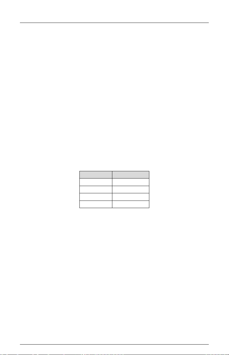
Page 10

MMU-16LE SmartMonitor
LEDguard
®
Green/Walk
Yellow
Red/Don’t Walk
Conflict
Low
Low
---
Red Fail
High
High
High
Dual Indicati on
Low
Low
Low
Clearance
Low
Low
High
Operati ons M an ual
make enhanced event logging, remote intersection monitoring, and remote diagnostics
feasible. Similarly, the MMU-16LE SmartMonitor
Unit whic h corr esponds to the C ontroll er Uni t output c omman ds to t he load s witches. T his
allows the MMU-16LE SmartMonitor
The TS2 St andar d als o provides f or mess ages t o be gener ated b y the Contr oller U nit and
the MMU-16LE SmartMonitor
®
to better respond to and diagnose fault situations.
®
which ext end th e c ommun ic ati ons cap abil ities of a st andar d
assembl y. T he Eber le Des ign MMU-16LE SmartMonitor
®
rec eives inf ormation f rom the Contr oller
®
us es t hes e m ess a ge f aci li ti es t o
provid e enh anced appl icati on sp ec if ic diagnostic r ep or ti ng an d m onitori ng.
1.4 FIELD SIGNAL TERMINALS
A GREEN , YE LLOW, or W ALK f ield sig n al inpu t wil l be s ens ed as acti ve by th e MMU -16E
SmartMonitor
®
wh en it exceeds t h e G reen, Yell ow , or Walk Signal D etect voltage t hreshold
(Section 8.1.2) and a field signal input will be sensed as inactive when it is less than the
Green, Yellow, or W alk Signal N o-Detect voltag e thresh old (Section 8.1.2). Both p ositive
and negative half wave rectified inputs will be sensed.
A RED (DO N’T W ALK) f i eld sig nal i nput will be s ens ed as acti ve b y t he M MU-16E when it
exceeds the Red Signal D etect voltage thr es hold (Section 8.1.2) and a field signal input will
be sensed as inactive when it is less than the Red Signal No-Detect voltage threshold
(Section 8.1.2). B ot h p ositive and n egative h alf w ave r ectifi ed inp uts wi ll be s ensed.
NOTE:
When the circuit connected to the sensing input of an MMU exhibits high
impedance char acteristics such as caused by dimmers, burned out lamps, low wattage
equipm en t, or n o load , it m ay b e necess ary to pl ace a low imp ed ance devic e ext ernal to th e
unit betw een the M MU input and AC NEUT RAL (See S ecti ons 5.5.3 .9 and 6.2 .4 of NEMA
Standards Publication TS2-2003 v02.06, Traffic Controller Assemblies With NTCIP
Requirements).
1.4.1 LEDGUARD® LED FIELD SIGNAL SENSING
®
The Eberl e Design MMU-16LE SmartMonitor
LEDguard
®
that is designed to better monitor the characteristics of LED based signal loads
c an be configured t o us e a t ec h niq u e called
(See S ection 6.3.4.7). E ach field si gnal inpu t is measur ed and co mpared to both a high
threshold and a low threshold value to determine On / Off status. This differs from
conventional stand ard Nema op eration wher e the active thr eshold is picked accor ding to
th e color of t he f ield signal. Once the high and low On / Off thresholds (Section 8.1.2) have
been det ermined us ing th e inp ut RMS vol t age, the in di vi dual f ault m onitor func ti ons use th e
appropriate threshold to determine if a fault condition exists.
1.4.2 TYPE SELECT INPUT
®
The MMU-16LE SmartMonitor
will op erate as a Type 16 mon itor with sixt een channels
when th e TYPE SE LECT input is a logic True (low ). The MMU-16LE SmartMonitor
operat e as a T ype 12 monit or with tw elve chan nels when t he TYPE SE LECT inp ut is a
logic False (high) or open circuit.
Type 16 - Each channel has three inputs: RED (DON’T WALK), YELLOW, and
GREEN (WALK).
Type 12 - Each channel has four inputs: RED, YELLOW, GREEN, and WALK.
®
The MMU-16LE SmartMonitor
is nor mally c onfigured as a 16 chann el (Type 1 6) monit or
when op er ated in a T S 2 typ e c abin et ass embl y. T he T ype 12 mod e is int end ed to pr ovid e
downw ard c ompati bi lity wit h 12 c han nel C onflic t M onitor Unit s (CMU ) c onf ormin g to NE MA
Eberle Design Inc. Page 4
®
will
Page 11
MMU-16LE SmartMonitor
Ped Phas e
MMU Channel
Phase 2 Ped
13
Phase 6 Ped
15
Phase 8 Ped
16
Operati ons M an ual
Traff ic Control S ystems Pu blicati on TS1-198 9. Wh en operatin g in the T ype 12 mode, the
MMU-16LE SmartMonitor
®
monitor ing f unct ions are th e sam e as the T ype 16 m ode exc ept
that Por t 1 com munic ations are dis abl ed and Fiel d Ch eck Mon itori n g is dis abled. See als o
TYPE 12 MODE WITH SDLC Option, section 1.4.2.1.
1.4.2.1 TYPE 12 WITH SDLC MODE
®
Th e M MU -16LE SmartMonitor
advantages of the Port 1 SDLC communications to the Controller Unit including Field
Check mon itori ng. In this mod e the MMU-16LE SmartMonitor
can operate in a N em a TS -1 config ured cabinet with t h e f ull
®
ch ann el displays op erate in
the Type 12 configuration displaying the Walk input status directly on the associated
vehicle channels (2, 4, 6, and 8). Certain requirements exist for this mode to operate
correctly:
1. T hi s m od e is li mi te d t o a ma xi mu m of f ou r P ed ph as es which mus t be assigned
to vehicl e phases 2, 4, 6, and 8. Th e Walk field t erminals must be wi red to th e
MMU-16LE SmartMonitor
®
channel inputs 2W, 4W, 6W, and 8W on MMU
connector pins MSA-y, MSA-FF, MSA-EE, and MSA-u respectively. This is
conventional wiring for a standard Nema TS-1 cabinet. MMU input TYPE
SELECT (pin #HH) must be “open circuit” (False).
2. The C ontrol ler Unit (CU) must be TS-2 Type 2 capabl e and provi de th e Port 1
EIA-485 c ommunic ations port. T he C ontroller Unit must b e config ured f or MM U
operation in the following areas (terminology and procedure may vary with
different brands of CU):
a. Enable the MMU in the CU Port 1 setup.
b. Add the Ped channels to the CU ring structure with the following
assignments:
See Section 6.3.4.9 for the T ype 12 wit h SD LC op tion setti n g.
Eberle Design Inc. Page 5
Phase 4 Ped 14
c. The CU Signal Driver Output mapping may need to be modified to
ensure that the CU is still driving the Ped load switches from the
correct output pins: MSA-J (2W), MSB-d (4W), MSC-LL (6W), and
MSC-d (8W).
3. TS-2 Controller Units provide an MMU utilization diagnostic that verifies the MMU
Program Card c hannel comp atibility to th e CU Driver Group U tilization (Nema
TS-2 clause 3. 9.3.1. 3). Depen din g on the CU capab iliti es, jum pers m ay need t o
be add ed t o t h e MM U -16LE SmartMonitor
®
Program C ar d p ermissi v e m atrix as i f
the Walk inputs were actually assigned to MMU channels 13 (2P), 14 (4P), 15
(6P), and 16 (8P).
®
Not e t h at t h e MMU -16LE SmartMonitor
will only use th e chann el 2, 4, 6, and 8
jumper pr ogramm ing for act ual conf lict detecti on. Pr ogram Card j umpers added
to channels 13, 14, 15, and 16 i n t h e Type 12 With SDLC m ode are only used by
the MM U -16LE SmartMonitor
®
t o s atis fy the ut i li z ation diagnost ic of the controll er
unit desc rib ed above.
4. A pr oper Port 1 EIA-485 r ated cable must b e connec ted b etween t he CU Por t 1
and the MMU-16LE SmartMonitor
®
Port 1.
Page 12

MMU-16LE SmartMonitor
Operati ons M an ual
1.4.2.2 FORCE TYPE 16 MODE
If the cab inet is alr eady wir ed for 16 channel operati on but the T YPE SELE CT inpu t is not
acces s i b l e du e t o c a bi n e t w ir i n g is s u es , t h e MM U -16LE SmartMonitor
®
can be forced t o the
Type 16 m od e by sett in g t h e F O RC E TYPE 1 6 opt ion in U nit Options. See Sect ion 6.3.4.8.
The FORCE TYPE 16 mode is not compatible with the TYPE 12 WITH SDLC mode
(section 1.4.2.1).
Eberle Design Inc. Page 6
Page 13

MMU-16LE SmartMonitor
Operati ons M an ual
Section 2
Standard Functions
2.1 CONFLICT MONITORING
When volt ages on any conf licting ch annels are sensed as acti ve for more th an the C onflic t
Fau l t t i m e ( S ection 9), th e MMU-16LE SmartMonitor
OUTPU T relay cont acts to t he Fault position, and display t he CONFLICT status s creen.
The MMU-16LE SmartMonitor
®
will remain in the fault mode until the unit is reset by the
RESET but t on or the EXT ER N A L R ESET input. When volt ag es on any conflicting channels
are sensed as active for less than the Conflict No-F ault ti m e, the MMU-16LE SmartMonitor
will not transfer the OUTPUT relay contacts to the Fault position.
®
The MMU-16LE SmartMonitor
is f ull y pr ogramm ab l e an d requir es the us e of soldered w ire
jumpers on an int erc h angeable Programming Card to defi n e p ermissive chan nel pair s . The
Program m in g Card is used wit h b oth Type 16 and T yp e 12 op er at i on. See Sec t i on 6.2.1 for
Programming Card details.
2.2 RED FAIL MONITORING
When volt ages on all inputs (G, Y, R, (W )) to a chann el are sens ed as in active f or more
than the R ed Fail F ault ti me (S ection 9), t he MMU-16LE SmartMonitor
mode, transfer the O UTPUT r elay contacts to th e F au lt p osi tion, and display the R ED F AIL
status s cr een. T h e MMU-16LE SmartMonitor
reset by t he RESET button or t h e EXT ER NAL RE SE T inp ut . When v oltages on all inputs t o
a chan nel are s ens ed as in act ive f or l ess th an t he R ed Fail N o-Faul t ti me, th e MMU-16LE
SmartMonitor
®
will not transfer the OUTPUT relay contacts to the Fault position.
Red Fail M on it or i ng wi ll b e d isabled when th e R ED EN ABLE inp ut is n ot ac t i ve. In the T yp e
16 mode, R ed Fail M onitori ng will also be dis abled if the LOAD S WIT CH FLAS H bit is s et
to "1" in the Type 0 message from the Controller Unit.
Programming is provided in the SET / VIEW CONFIG menu item to enable Red Fail
Monitor ing on a per ch ann el b as is . See Section 6.3.3 for the program mi ng pr oc edure.
2.2.1 RED ENABLE INPUT
The RED ENA BLE in put will be sens ed as activ e by the MMU-16LE SmartMonitor
exceeds the Red Enable Input threshold (Section 8.1.2). The presence of the proper
operatin g voltag e at this input enab les Red Fai l Monitori ng, Minimu m Yellow Ch ange/Red
Clear ance Monitorin g, and Dual Ind icati on Monitori ng. I n the T ype 16 mod e, if the LO AD
SWITCH FLASH bit is set t o "1" in the T ype 0 mess age fr om the Contr oll er Unit, R ed Fail
Monitor ing will be disabled.
The main status screen will display “RED ENAB LE IS OFF” if the RED ENABLE input is not
active. I n the Typ e 16 mode, if the LOAD SWIT CH FLASH bit is set t o "1 " in t h e Ty pe 0
message fr om the Controll er Unit, the main status screen will display “CU LS-FL ASH i s
SET”.
2.2.2 WALK DIS A BLE O PTIO N
This opti on wi ll mod if y the oper ati on of R ed Fail an d Du al Indic at ion M onitor in g in the TS -1
Type 12 mode onl y. When en abled, t he Red F ail and D ual Indic ation Moni toring f unction
will not monitor t he W alk field outputs. Absenc e of sig nals on th e Gr een, Yell ow, and R ed
field outp uts of a channel will pl ace the MMU-16LE SmartMonitor
mode causing t h e O u tp ut r elay con tacts t o tr ansf er. Pr esenc e of active si gnals on t h e Walk
outputs will n ot caus e a Dual In dic ation w hen c oncur rent with acti ve Red or Yel low sign als.
This f unction is en abled by th e Unit Opti on called "W ALK DISABLE" in the SET / VIEW
CONFIG m enu. See Section 6.3.4.2.
®
will enter the faul t mod e, tr ansf er th e
®
will ent er the f ault
®
will r emain in t he f ault mod e un til th e un it is
®
when it
®
int o the Red Fail f ault
®
Eberle Design Inc. Page 7
Page 14

MMU-16LE SmartMonitor
Operati ons M an ual
2.3 VOLTAGE MONITORING
2.3.1 +24VDC SUP PLY MONITORING
The +24V MONITOR I and +24V MONITOR II inputs are provided for monitoring two
+24Vdc su pplies in the c abinet assem bly. Shou ld loss of proper voltage occur at ei ther of
these inputs , th e MMU-16LE SmartMonitor
relay contacts to the Fault position, and display the appropriate 24V-1 or 24V-2 status
screen. The MMU-16LE SmartMonitor
correct inp ut voltages are restored to both of thes e inputs. The MMU-16LE SmartMonitor
®
will enter th e fault m od e, transf er the OUTPUT
®
will automatically reset the OUTPUT relay when the
®
will remain in the fault mode for at least the time determined by the Minimum Flash
programming.
A voltage gr eater than th e +24V M onit or input t hres hold (S ection 8.1.4) appli ed to bot h of
the +24V MON ITOR in puts will b e sens ed b y the MMU-16LE SmartMonitor
®
as adequ ate
for operation of the cabinet assembly. A vol tage less than t he +24V M onit or input thres hol d
applied t o either of the +2 4V MONITOR inp uts will be sens ed as inadequ ate for pr oper
operati on. W h en a +24V MON ITO R inp ut is s ens ed as inad equ at e for mor e th an the +24V
Monitor F aul t tim e (S ecti on 9), th e MMU-16LE SmartMonitor
®
will ent er the f ault mod e and
transfer the O UTPUT r elay cont ac t s t o t h e F aul t p os ition. When a + 24V MON ITOR i np ut is
sensed as inadequate for less than the +24V Monitor No-Fault time, the MMU-16LE
SmartMonitor
®
will not t rans fer t he OUT PUT r elay c ontac ts t o th e Fault p ositi on. A + 24Vdc
failure dur ing the progr ammed Minimu m Flash time or duri ng an MMU Power Fail ure will
not cause a fault condition.
2.3.1.1 +24VDC MONITOR INHIBIT INPUT
A +24V MON ITOR INH IBIT inp ut is pr ovi d ed t o inhib it t he oper ati on of t h e + 2 4Vdc M onitor.
Applic ation of a l ogic T R U E ( l ow) s t at e t o th i s in pu t will disable th e op erati on of th e +24Vdc
Monitor.
2.3.1.2 +24VDC MONITOR LATCH INPUT
A jumper p osit ion is supp lied on the Pr ogr ammi ng C ard t o allow +2 4 Vdc f ailur es to l atch in
the fault condition until the unit is reset by the activation of the RESET button or the
EXTERNA L RESET input. See Section 6.2.4 for the programm ing procedure. A +24Vdc
failure dur ing the progr ammed Minimu m Flash time or duri ng an MMU Power Fail ure will
not cause a latched fault condition.
2.3.1.3 +24VDC MONITOR II 12VDC MODE
®
The MMU-16LE SmartMonitor
offers th e capabilit y of setting t he threshol d for the +24V
MONITO R II inpu t to l evels suit able f or monitor ing a 12 V dc pow er sup ply. This mode is
enabled by the Unit Option call ed " 24V-2 = 12 V dc " in the SET / V IE W CONFIG menu. See
Section 6.3.4.5.
2.3.2 CONTROLLER VOLTAGE / FAULT MON ITOR INPUT
This input is to be connected to the CONTROLLER UNIT VOLTAGE MONITOR (CVM) or
FAULT MONITOR (FM) output from the Controller Unit. W hen the TRUE (low) state is
absent for more than the C VM Fau lt tim e (Section 9), the MMU-16LE SmartMonitor
®
will
enter the f ault mod e, tr ansf er the OUT PUT r elay c ontacts t o the Fau lt p ositi on, and display
the CVM status screen. When the T RUE (low) s tate is abs ent for less than t he C VM NoFault time, t he MMU-16LE SmartMonitor
the Fault position. The MMU-16LE SmartMonitor
relay wh en th e Tru e (low ) st ate is r estor ed t o the in put. The MMU-16LE SmartMonitor
®
wil l not tr ansfer t he OUTP UT relay c ontacts to
®
will automatically reset the OUTPUT
®
will
remain in the fault mode for at least the time determined by the Minimum Flash
programming. A CVM failure during the programmed Minimum Flash time or during an
MMU Power Failure will not cause a fault condition.
Eberle Design Inc. Page 8
Page 15

MMU-16LE SmartMonitor
Operati ons M an ual
2.3.2.1 CVM MONITOR LATCH INPUT
A jumper position is supplied on the Programming Card to allow CVM failures to latch in the
fault condition until the unit is reset by the activation of the RESET button or the
EXTERNAL RESET input. See Section 6.2.4 for the programming procedure. A CVM
failure d uring th e progr ammed Minimum F lash time or duri ng an MMU Power Failur e will
not cause a latched fault condition.
2.3.2.2 CVM LOG DISABLE
If CVM even ts ar e not relat ed to a malf unc ti on con diti on an d occur on a reg ular basis suc h
as Time of Day flash, the logging of these events can be disabled. See Section 6.3.4.3.
2.4 LOCAL FLASH STATUS INPUT
This inp ut is to be c on n ect ed to th e Auto/Fl as h s w itc h in t h e cabinet. When th e TR U E (low)
state is present for more than the Local Flash Fault time (Section 9), the MMU-16LE
SmartMonitor
position, and display the LOCAL FLASH status screen. W hen the TRUE (low) state is
present f or less th an th e L oc al Fl as h No-Fault tim e, the MMU-16LE SmartMonitor
tr ansf er the OUTPUT relay contacts to the Fault position. The MMU-16LE SmartMonitor
will aut omaticall y r eset th e OUTPUT relay when th e False (hig h) state is r estored to th e
input. The MMU-16LE SmartMonitor
®
wil l enter th e fault mode, tr ansfer th e OUTPUT relay c ontacts t o the Fault
®
will not
®
will r emain in the fault mode f or at least th e time
®
determined by the Minimum Flash programming. A Local Flash condition during the
Minimum Flash time or during an MMU Power Failure will not cause a fault condition.
2.5 MINIMUM YELLOW CHANGE / RED CLEARANCE MONITORING
2.5.1 MINIMUM YELLOW CHANGE INTERVAL
®
The MMU-16LE SmartMonitor
will verif y that the Yellow C hange interv al is at least the
Clear ance Fail F ault ti me (S ection 9). The Y ellow Ch ange int erval c onsis ts of th e durati on
of time in which the Yellow field signal input is active in a sequence from Green to Yellow to
Red. W hen this min imum int erval is not satisfi ed the MMU-16LE SmartMonitor
®
will ent er
the fault m ode, trans fer the O UTPUT relay contac ts to the F ault positi on, and display the
SKIPPED Y CLEARANCE or SHORT Y CLEARANCE status screen. The MMU-16LE
SmartMonitor
®
will r emai n in th e fault mode u ntil th e unit is res et by th e RESET butt on or
the EXTERNAL RESET input.
Minimum Yellow Change Monitoring will be disabled when the RED ENABLE input is not
active.
2.5.1.1 MINIMUM YELLOW CLEARANCE DISABLE
A set of s older ed wir e jum pers is pr ovided on the P rogr amming C ar d to dis able Minimum
Yellow Ch ange Mon itorin g on a per ch annel bas is. See Sect ion 6.2.3 for th e pr ogram min g
procedure.
2.5.2 MINIMUM YELLOW PLUS RED INTERVAL
®
The MMU-16LE SmartMonitor
will verify that the Yellow Change plus Red Clearance
interval bet ween t h e end of an ac tive G reen ( or W alk) si gnal and th e b eginn ing of th e next
conflic ting G reen ( or W alk) sig nal is at leas t t he Clear anc e F ail F ault t i m e ( S ecti on 9). This
ensures a minimu m clearance int erval for channels without a true yellow sign al such as
pedestrian channels. When this minimum interval is not satisfied the MMU-16LE
SmartMonitor
position, and display the SHORT Y+R CLEARANCE status screen. The MMU-16LE
SmartMonitor
®
wil l enter th e fault mode, tr ansfer th e OUTPUT relay c ontacts t o the Fault
®
will r emai n in th e fault mode u ntil th e unit is res et by t he RESET butt on or
the EXTERNAL RESET input.
Yellow C hange plus Red Clear ance Monit oring will be disabl ed when the R ED ENABL E
input is not active.
Eberle Design Inc. Page 9
Page 16

MMU-16LE SmartMonitor
Operati ons M an ual
2.5.2.1 MINIMUM YELLOW PLUS RED CLEARANCE DISABLE
The Red + Yell ow Clear anc e Disabl e Conf igur ation sc reen is provi ded in t he SET / VIEW
CONFIG menu to disable Minimum Yellow Plus R ed Chang e Monitori ng on a per channel
basis. Provision to disable this function is not provided for in the NEMA Standards
Publication TS2-20 03 v 02. 06.
The MUTCD Sectio n 4D.10 Yell ow Change a nd Red Clear ance Inter vals requirement
states, “ A yellow s ig nal indication s h all b e display ed foll owing every CIR CU LA R G R EE N or
GREEN A RROW s ignal indic ation”. I n some leg acy inters ection cas es this requir ement is
not met due t o th e lac k of a Yell ow s ign al head on an overl ap phase (ch annel) , and signal
timing th at precludes what would nor mally be the over lap clearanc e interval. I n this c ase
the Minimum Yellow Plus Red Clearance monitoring function can be disabled for that
channel. It should be noted that the Minimum Yellow Plus Red Clearance monitoring
function is only intended to be disabled under these special conditions.
See Sect i on 6.3.7 for t he pr ogr amm ing proc edur e. The default setting for Minimum Yellow
Plus Red Clearance monitoring is Enabled.
2.6 MMU POWER FAILURE DETECTION
W h en the AC LINE voltage is below the minimum AC Line drop-out l ev el (Section 8.1.3) for
the MMU Power F ail Respond t i m e (S ecti on 9), the MMU-16LE SmartMonitor
®
will s us p end
all fault m onitor ing func tions, de-en ergize t he OUTPU T rel ay, and d e-en er gi z e th e S TA RT
relay. Th e POW ER indicator on t he front p an el will fl ash at a rate of 2Hz t o indicate the low
voltag e status. The main st atus displ ay will indicat e “AC LI NE BROWN OUT” and displ ay
the curr ent AC Li n e input volt ag e.
When th e AC LINE vol tage returns above the maximu m AC Line r estor e lev el (Section
8.1.3) for t he MMU Pow er Fail Rest ore time (S ection 9), the monitor will r esume nor mal
operation and the POWER ind ic ator on th e fr ont pan el will rem ain il lum inat ed. Aft er a 2.0 +_
0.5 second delay the START relay will be energized. After a programmable delay
determined by the Minimum Flash programming, the OUTPUT relay will be energized (see
Section 6.2.2).
This expanded operating voltage range for cabinet components allows the MMU-16LE
SmartMonitor
orderly manner when th e AC LINE volt age is suff icient for proper operation. The MMU16LE SmartMonitor
®
to place the intersection into flash and return to normal operation i n an
®
sh ould be t he first c ompon ent in the c abinet t o sens e a low volt age
conditi on and th e l ast c om p onent to sense a proper AC LIN E op erating vol t ag e.
The AC LINE an d AC NEUT RA L inp uts ar e us ed t o gen erat e th e int ern al voltag e s uppl i es
requir ed t o oper at e the moni tor . AC N EU TR AL als o s erves as t he r etur n f or al l AC s ign als
including RED ENABLE. EARTH GROUND provides an independent connection to the
chassis of the unit and is isolated from AC NEUTRAL and LOGIC GROUND. LOGIC
GROUN D is provi d ed for in puts w hich are isolat ed f rom AC N EU T RAL ( i. e. +24V M onit or s ,
CVM, CONTROLLER W ATCHDOG, EXTERNAL RESET, and 24V MONITOR INHIBIT).
LOGIC GROUND may be tied to AC NEUTRAL if desired.
2.7 PORT 1 COMMUNICATIONS
When op erating in t he Type 16 m ode and c onnected t o a TS2 Con troller U nit, the MMU16LE SmartMonitor
®
has th e ability to exch ange infor mation in a stan dardiz ed format with
the Controller Un it using Port 1. For details on mess age formats refer to Secti on 3.3.1,
NEMA Standards Publication TS2-2003 v02.06, Traffic Controller Assemblies With
NTCIP Requirements.
The information transmitted from the Controller Unit to the MMU-16LE SmartMonitor
consist s of th e follow ing m essag e types : load s witch dri ver com mands (T ype 0), time and
date (Type 9). The information transmitted from the MMU-16LE SmartMonitor
®
to the
Control ler Uni t consis ts of t he foll owing m essag e types : field si gnal s tatus and fault s tatus
Eberle Design Inc. Page 10
®
Page 17

MMU-16LE SmartMonitor
Fault Type
Bit #
Nema Desi gnation
Field Ch ec k F ault / St at us
67
Spare Bit #1
RP Detection Status
69
Spare Bit #3
External Watchdog Fault
70
Spare Bit #4
Operati ons M an ual
(Type 129), channel compatibility programming (Type 131). The load switch driver
command (Type 0) and field signal status (Type 129) messages are exchanged
approxi m ately ever y 1 00 msec.
The electrical interface used for Port 1 conforms to the requirements of the Electronic
Industri es As soci ation EIA -485 Standard. It is designed for balanced digital multipoint bus
systems an d provides fu lly different ial signal oper ation. The baud r ate used is 153. 6K bit
per second. The Port 1 connector intermates with a 15 pin D type connector, AMP
Incorp orated part nu mber 205206-1 or equivalent. The Port 1 connect or pin assign ments
are shown in Section 10.6.
The data and clock communications protocol used for Port 1 is a subset of the
Synchr onous Data Link C ontrol (SDLC) Protoc ol, as defined by Internatio nal Busine ss
Machines Corporation Document GA27-3093-3 (June 1986). This protocol utilizes
sophisticated error checking computations to verify message integrity. In addition, the
Eberle Design MMU-16LE SmartMonitor
®
ad ds enh anc ed c ommunic at ions diag nost ics and
error handling capabilities to ensure proper communications occur.
2.7.1 PORT 1 TIMEOUT
When a T ype 0 messag e from the Con troller U nit has not b een corr ectly recei ved for the
Port 1 Timeout Fau lt time (Section 9 ), the MMU-16LE SmartMonitor
®
will enter t he f ault
mode, tr ansfer the O UTPUT relay contacts to the Faul t positi on, and display the PORT 1
FAIL status screen. When receipt of a Type 0 message again occurs, the MMU-16LE
SmartMonitor
®
will exit the fault state and transfer the OUTPUT relay contacts to the norm al
positi on, e xc ep t when three Por t 1 f aul ts h ave oc c urred in a c alen d ar d ay.
®
After t he thir d Por t 1 f ault i n a c alendar day, the MMU-16LE SmartMonitor
will remain in
the fault m ode unt il the unit is r eset b y the RESE T but ton or the EX T ERN AL RES ET inp ut.
Loss of AC Li ne after the th ird P ort 1 f ault wi ll exit the f ault st ate and res et the P ort 1 f ail
count to 2.
A PORT 1 timeou t failure dur ing the progr ammed Min imum Flash t ime or durin g an MMU
Power Failure will not cause a latched fault condition.
2.7.2 PORT 1 DISABLE INPUT
Port 1 communications will b e disabled when th e P O RT 1 DIS A B LE input is at a logic True
(low) st ate OR the TYPE S ELECT input is at a logic Fals e (high) stat e (Type 12 mode) .
Port 1 communic ations will be enabled wh en th e P O RT 1 DISA B LE i nput is at a l ogic F alse
(high) state AND the TYPE SELECT input is True (low) (Type 16 mode).
2.8 TYPE 12 9 RESPONSE FRAME
Five bits desi gnat ed as S p are Bi t #1 thr ou gh Sp are bi t #5 of the T ype 129 r espons e f ram e
to the Controller Unit are used by the MMU-16LE SmartMonitor
failure detected for enhanced fault monitoring capabilities of the MMU-16LE. Refer to
sections 3.9, 3.2, 3.7, 3.2.1, and 2.5.2 of this manual for further information.
Eberle Design Inc. Page 11
®
to i ndic ate t he ty pe of
Dual Indication Fault 68 Spare Bit #2
Yellow Plus Red Clearance 71 Spare Bit #5
Page 18

MMU-16LE SmartMonitor
Operati ons M an ual
2.9 OUTPUT RELAY RECOVERY
®
Prior to the MMU-16LE SmartMonitor
trans ferring the Output Rel ay c ontacts f r om the f ault
stat e to th e no-fault st ate, a tr ansition state w ith duration of 50 0 milliseconds will occur.
During t he transit ion state th e Output Relay wil l remain in t he fault s tate and th e Start-up
Flash Call bit in the Type 129 frame will be set to 1.
2.10 INTERNAL DIAGNO S TICS
®
The MMU-16LE SmartMonitor
capabilities whic h monitor for c orrect operati on of the MMU-16LE SmartMonitor
is su pplied with a r esident s eries of self ch eck diagn ostic
®
both at
power-up and continuously during operation. Should an internal diagnostic error occur,
other f ault indicat ors that may b e concurrent ly displayed with the DIAGNOSTIC indicator
may not be val i d du e to t h e nature of thes e h ar d w are an d/or firm w ar e failures.
2.10.1 MEMORY DIAGNOSTICS
®
On power-up, the MMU-16LE SmartMonitor
components including RAM, EPROM, and non-volatile EEPROM. During operation the
MMU-16LE SmartMonitor
volatile memory components. When either diagnostic test fails, the MMU-16LE
SmartMonitor
®
wil l enter th e fault mode, tr ansfer th e OUTPUT relay c ontacts t o the Fault
®
continuously performs a check sum verification of the non-
verifies the operation of all memory
positi on, and ill uminat e the DIAG NOSTIC i ndic ator. An MMU Power Failure will reset the
Diagnostic fault state of the monitor (see Section 2.6). Due to the nature of these
har dw are/ fir mwar e f ailu res, ot her f aul t ind ic ators th at may be c oncurrently d isplayed with
the DIAGNO STIC indicat or may n ot b e val id.
2.10.2 MICROPROCESSOR MONITOR
®
The MMU-16LE SmartMonitor
contains circuitry which monitors the operation of the
internal microproc essor. This monitoring c ircuit rec eives a logic transition s ignal fr om the
micropr ocess or ever y 5 msec. When th is logic trans ition is not rec eived f or 300 ms ec, th e
MMU-16LE SmartMonitor
®
will enter th e fault m od e, t r ans fer th e OUTPU T relay contac t s t o
th e Fault position, and illuminate the DIAGNOSTIC indicator. Due to the nature of these
hardw are/f irmware f ailures, oth er fault ind icators that may be conc urrently dis played wit h
the DIAGNO STIC indicat or may n ot b e val id.
This t ype of f ailur e is c onfigur ed as latch ing. I f the micropr ocessor resumes op eration th e
unit wil l not ret urn to nor mal op eration. With l atchin g operat ion, only a loss of AC Li ne will
restore operati on. I f non-latch ing operat ion is desir ed, internal jumper E1 ( Latching MPU
Fault) may b e r em o ved .
2.10.3 INTERNAL HARDWARE MONITOR
®
The MMU-16LE SmartMonitor
sections of the internal circuitry. Should a malfunction be detected, the MMU-16LE
SmartMonitor
®
wil l enter th e fault mode, tr ansfer th e OUTPUT relay c ontacts t o the Fault
cont ains circuitr y which verifies the oper ation of the many
position, and illuminate the DIAGNOSTIC indicator. An MMU Power Failure will reset the
Diagnos tic f ault st ate of the m onitor (s ee Sec tion 2.6). D ue to t he n ature of this hard ware
failure, other f ault indicators that may be c oncurrently displayed with the DIAGNOSTIC
indic ator m ay n ot b e vali d.
Eberle Design Inc. Page 12
Page 19

MMU-16LE SmartMonitor
Operati ons M an ual
Section 3
Enhanced Features
The following enhanced features are provided on the Eberle Design MMU-16LE
SmartMonitor
16LE SmartMonitor
3.1 HARDWARE FEATURES
The MMU-16LE SmartMonitor
functions and features are firmware programmable which permits upgrades or
modific ations b y simply reprogramming the Flash mem ory devic e contai ning th e firmwar e
with the upgraded version. Thus, most changes to the MMU-16LE SmartMonitor
specif ications m ay b e accommodated without modifying th e har d ware.
Since all critical timing functions are accomplished by the microprocessor, the quartz
crystal based accuracy results in very precise and repeatable measurements. This
accurac y is mai ntai ned on f uncti ons f rom timi ng faul t c onditions to imp lement ing a uniqu e
firmw are based digi tal sampli ng and filt ering alg orithm. This algorit hm is appli ed to all AC
field signals to help eliminate false detection in a "noisy" AC line environment.
Input voltages are measured using a true Root Mean Squared (RMS) technique. A
dedic ated mic rocontrol ler RMS-Engine
samples each AC input voltage at least 32 times per cycle. The RMS-Engine
calculates the true RMS voltage value, producing accurate results which are very
insensit i v e t o c hanges in frequ ency, ph as e, wav e s hape, an d d is tortion. V ol t a g e r efer e nces
are tem per atur e c ompens at ed f or c onst ant vol tag e lev els wit hin t h e op eratin g temper atur e
range.
A nonvol atile E EPROM device is utiliz ed to ret ain fault s tatus informat ion and event l ogs
through an A C Line pow er interr upti on. The corr ect fault indic ations wi ll be displ ayed up on
restor ation of A C Lin e pow er . This EE PROM d evic e requir es no batter y back-up. The time
of day in the MMU-16LE SmartMonitor
Should this battery fail, only current time of day and date information will be lost. No
monitor configuration programming is stored under battery power.
®
for additional monitoring functions and to increase the reliability of the MMU-
®
monit or op eration.
®
is a dual microprocessor based unit. All monitoring
®
cont rols th e analog t o digit al (A/D) hardwar e that
®
is stored in a b attery-backed real time clock circuit.
®
then
®
3.2 DUAL INDICATION MONITORING
In Type 16 m od e t his m on itoring f unc tion det ec ts s im ultaneous input c omb in at ions of act i v e
Green (Walk), Yellow, or R ed ( Don’t Walk) field sign al in pu ts on th e s am e c h ann el. In Type
12 mod e this m onit ori ng fu ncti on d et ects s im ultan eous in put c ombin ations of act iv e Gr een
and Yellow, Green and Red, Yellow and Red, Walk and Yellow, or Walk and Red field
signal inputs on the same channel. When voltages on any two inputs of a channel are
sensed as act ive for mor e than the Du al Indic ation F ault time ( Secti on 9), the MMU-16LE
SmartMonitor
®
wil l enter th e fault mode, tr ansfer th e OUTPUT relay contacts to the Fault
positi on, and display the DUAL INDICATION status screen. When operating in the Type 16
mode with Port 1 communications enabled, Bit #68 (Spare Bit #2) of the Type #129
response fram e w il l be set to indicate a Dual In dication fault h as been detect ed . The MMU16LE SmartMonitor
button or the EXT ERNAL RES ET input. W hen voltages on an y two inputs of a channel ar e
se n sed as acti ve for les s than the Dual Indication Fault time, the MMU-16LE SmartMonitor
®
will remain in the fault mode until the unit is reset by the RESET
®
will not transfer the OUTPUT relay contacts to the Fault position.
Dual In dicati on Monit orin g may an ticip ate and pr even t a poss ible c onflictin g sign al dis play
in the inters ecti on in the event that a pr oceed sig nal on th e curr ent ph ase h angs up and is
const antly det ected as active. A n open or no load c ondit ion (i. e., bur ned-out b ulb) m ay be
also det ected as an acti ve sign al dep endi ng on th e outp ut imp edanc e ch ar acteris tics of th e
load switch (i.e. load switch le ak ag e current), and may cause a Dual I ndication Fau lt .
Eberle Design Inc. Page 13
Page 20

MMU-16LE SmartMonitor
Operati ons M an ual
Programming f or Dual Indic ation is provided in th e SET / VIEW CONFIG menu item to
enable Dual Indication Monitoring on a per channel basis. See Section 6.3.2 for the
programming procedure.
Dual Indication Moni toring will be disabled when the RED ENABLE input is not a c tive.
3.2.1 WALK DIS A BLE O PTIO N
This option will modify the operation of Red Fai l and Du al Indic at i on M onitorin g i n t h e T S -1
Type 12 mode onl y. When en abled, t he Red F ail and D ual Indic ation Moni toring f unction
will not monitor t he W alk field outputs. Absenc e of sig nals on th e Gr een, Yell ow, and R ed
field outp uts of a channel will plac e the MMU-16LE SmartMonitor
®
int o the Red Fail fault
mode causing t h e O u tp ut r elay con tacts t o tr ansf er. Pr esenc e of active si gnals on t h e Walk
outputs will n ot caus e a Dual In dic ation w hen c oncur rent with acti ve Red or Yel low sign als.
This f unction is en abled by th e Unit Opti on called "W ALK DISAB LE" in the SET / VIEW
CONFIG m enu. See Section 6.3.4.2.
3.3 EXTERNAL WATCHDOG MONITORING
This func tion monit ors an option al exter nal watchd og outpu t from a Control ler Unit or oth er
extern al c abin et c ircu itr y. Th e ext er nal s ourc e s houl d togg le th e E XT ER NAL W AT CH DOG
input l og ic s tate once ev er y 1 00 msec . If th e MMU-16LE SmartMonitor
change in stat e on the EXTER NAL WATCH DOG input for t he External W atchdog Fault
time (Section 9), the MMU-16LE SmartMonitor
®
will enter the fault mode, transfer the
®
d oes n ot recei ve a
OUTPUT relay contacts to the Fault position, and display the EXT W ATCHDOG status
screen. When operati ng in th e Type 16 m od e w ith Port 1 comm un ic at i ons en abled, Bit #70
(Spare Bit #4) of the Type #129 response frame will be set to indicate an External
W atchdog fault has been d etect ed. Th e MMU-16LE SmartMonitor
®
will r emain in th e fault
mode un til t he unit is r es et b y th e R ES ET butt on or t h e EXTERNAL RESET input. A n MMU
Power F ailur e will als o res et t he External Watchdog f ault st ate of t he m onit or (s ee S ec tion
2.6).
This f unc tion is enabled by a UNIT Option called EXTERN W AT C HDOG in the SET / VIEW
CONFIG men u ( see Sect ion 6.3.4.4). The EXT ERNAL W AT CHDOG inp ut is har nessed t o
spare pin MSB-S on the front panel B connector by the factory.
3.4 PROGRAM CARD ABSENT INDICATION
If the Pr ogram Card is abs ent or n ot seated pr operly i n th e edge connector, t he MMU-16LE
SmartMonitor
®
wil l enter th e fault mode, tr ansfer th e OUTPUT relay c ontacts t o the Fault
positi on, and display the PGM CARD AJAR status screen. The MMU-16LE SmartMonitor
will r em ain i n the fault m od e u ntil th e Program Card is correc tl y seated an d the MMU-16LE
SmartMonitor
®
is reset by the RESET button or the EXTERNAL RESET input.
3.5 RESET INPUT DETECTION
Activati on of the front pan el RESET button or th e EXTERNA L RESET input will r eset th e
MMU-16LE SmartMonitor
®
from th e fault mod e an d c ause the START relay t o energiz e an d
th e O UTP U T r el a y t o tra ns fer t o t h e n o-f ault s tat e. E ach activat i on o f the R ESET but ton or
EXTERNAL RESET input will cause a one time reset input to the unit. A continuously
activat ed R ESET inp ut w ill n ot prev ent th e MMU-16LE SmartMonitor
®
f rom monit oring an y
fault condition and/or transferring the OUTPUT relay contacts to the fault position. This
functi on pr events the Cab in et Ass embl y fr om bein g oper at ed with t he m onitor unit dis abled
due to a faulty RESET button or EXTERNAL RESET input.
3.6 DISPLAY LED TEST
The monitor will illuminate all front panel LED and LCD in dic ators f or 500 ms w hen a Reset
command is issu ed by the f ront panel RESET b utton or E XTERNAL R ESET inp ut. This
functi on provides a m eans to check the operati on of all front pan el in dicators.
Eberle Design Inc. Page 14
®
Page 21

MMU-16LE SmartMonitor
Operati ons M an ual
3.7 RECURRENT PULSE DETECTION
This err or detect ion funct i on s u pp lements t h e n ormal Conf lic t, Dual Indic ati on , and Red F ail
monitoring algorithms for sensing faults which are intermittent or pulsing in nature. The
RMS-Engine
®
is designed to filter out short term transients commonly found on the
electrical service and pr ovi de nois e i mmunity ag ai ns t f alse signal detect i ons . The Recu rr e nt
Pulse det ection fu nction is d esigned t o respond t o fault conditi ons whic h are inter mittent in
nature and do not meet the continuous timing requirements of the normal detection
algorithms, yet may still produce improper signal displays. These input conditions are
differentiated by their longer time constant and fault response times.
The f igure bel ow s hows a simple examp le of a Rec urrent Conflic t fault. Channel 2 G reen is
detect ed act ive d ue t o a m alfu ncti on of the l oad s witc h whic h c aus ed the out put t o “flic k er”
On for 100 ms appr oximat ely ever y 200 ms. Because norm al Conf lict d etecti on requir es a
continu ous f ault of at least 350 ms t ypic al, this event c ould g o unde tected. Th e R ecur re nt
Pulse det ection algorith m will process th ese pulses i nto one even t and trig ger a Conf lict
fault once the longer recurrent timing threshold is exceeded.
®
When triggered by a recurrent pulse fault condition, the MMU-16LE SmartMonitor
will
enter th e fault mode, tr ansfer t he Output relay c ontacts t o the Fau lt pos ition, and display
the approp riate RP CONFLICT, RP DUAL INDICATION, or RP RED FAIL status scr een.
The unit wil l rem ain i n t he f ault mod e un til r eset b y the R es et but ton or the E xt ernal R es et
input. Faul t respons e times will vary dep ending on the pulse widt h and frequency of the
recurrent inputs, but typically range from 1000 ms minimum to 10 seconds maximum.
This f unction c an be dis abled by a UNIT Option called REC URRENT PU LSE in the SET /
VIEW CONFIG menu. See Secti on 6.3.4.1.
3.8 TYPE FAULT
®
The TYP E SE LECT inp ut is us ed b y th e MMU-16LE SmartMonitor
to spec ify whether the
monitor is to be c onfig ured as a Type 16 unit with 16 c hannels or a T S1 comp atible T ype
12 unit with 12 channels (see Section 1.4.2). This input is read by the MMU-16LE
SmartMonitor
button or EXTERNAL RESET input. The Type Select configuration of the MMU-16LE
SmartMonitor
®
on ly during power-up initial ization or when th e unit is reset by th e RESET
®
can only be modified when the unit is reset by the RESET button or
EXTERNA L RESET in put. This prevents t he possibi lity of the MMU-16LE SmartMonitor
changi ng its c onfigu r ation mod e du e t o the f ailur e of th e c abinet T YPE SELECT ju mper or
the monitor TYPE SELECT input.
Once the unit is programmed by a reset command, its configuration mode (Type 16 or Type
12) is stored in non-volatile memory. During power-up initialization, the MMU-16LE
SmartMonitor
SELECT in pu t. If they are dif f er ent , th e MMU-16LE SmartMonitor
transfer the OUTPUT r elay contacts to the Fault position, and display the TYPE 12/16
FAULT s t at us s c reen . The MMU-16LE SmartMonitor
unit is reinitialized with the TYPE SELECT input in the proper state or the MMU-16LE
SmartMonitor
®
c omp ar es t he progr ammed c onfigurati on mode wit h the stat e of the TYP E
®
will remain in the fault mode until the
®
is reset by the RESET button or the EXTERNAL RESET input.
®
will enter the fault mode,
®
Eberle Design Inc. Page 15
Page 22

MMU-16LE SmartMonitor
Operati ons M an ual
3.9 FIELD CHECK MONITORING
®
Field Check Monitoring is an enhanced function of the MMU-16LE SmartMonitor
utilizes the Port 1 communications between the Controller Unit and the MMU in a TS2
Cabinet Assembly. When operating in the Type 16 mode the MMU-16LE SmartMonitor
that
®
will
receive th e Type 0 mes sage from the C on troller Unit (T ype 1 or T yp e 2 C U ) w hic h contai ns
an imag e of the contr oller out put c ommands t o the load swit ches. W hen a fault c ondition
triggers the MMU-16LE, th e Typ e 0 mes s age inf ormat i on rec ei ved whil e th e f ault c onditi on
was being timed will be used by the MMU-16LE SmartMonitor
®
to determine whether the
sensed field s i gn al input status corresp onded to the Contr oll er Unit o utp ut comm an ds . T his
diagn ostic infor mation is then us ed by the Diagnostic Wizard to is olate wheth er the fault
conditi on w as caus ed b y a Con tr oller U nit m alfu nct ion or a failur e i n the load sw itch and/ or
field wiri ng. In th e latter cas e, the W izard then pinpoints the f aulty inputs of the ch annels
involved in the fault condition.
The Field Check Monitor function is enabled for each channel input individually (see
Section 6.3.1) and provi des tw o modes of oper ation, F ield Chec k Fault and Field Chec k
Status.
3.9.1 FIELD CHECK FAULT
In the F ield Check Fault m ode, when th e field signal input st ates sensed as acti ve or
inactive by the MMU-16LE SmartMonitor
Controller Unit in the Type 0 message for 10 consecutive messages, the MMU-16LE
SmartMonitor
®
wil l enter th e fault mode, tr ansfer th e OUTPUT relay c ontacts t o the Fault
®
d o not c orr esp ond with t he d ata pr ovi ded b y th e
positi on, and display the FIELD CHECK FAULT status screen. The Channel S t at us Dis play
will indic ate t he channels on which the F ield Check error was d etected (s ee Section 7.2
Channel S tatus D isplay). B it #67 (S pare Bit #1) of the T ype #129 res ponse f rame will b e
set to indic ate a F ield C heck f ault has b een d etected. Th e MMU-16LE SmartMonitor
®
will
remain in the f ault mode until the unit is reset by the RESET button or the EXTERNAL
RESET input. The Field C heck Fail Monitoring function is automatically disabled in the
Type 12 mod e, and in th e T ype 1 6 mod e wi th th e POR T 1 D ISAB LE input T ru e (low ). T he
Field Ch eck Fail M onitoring f unction is also dis abled when t he RED E NABLE input is not
active.
3.9.2 FIELD CHECK STATUS
The Field Check Status mode works in combination with the other fault monitoring
functions of the MMU-16LE SmartMonitor
®
to produce additional diagnostic information
about t he detected fault. The Field C heck Monit or func tion will b e collecting status and
timing a Field Check Faul t if t he s ensed fi eld sig nal in put st ates do not c orres pond t o th e
Type 0 m essag e data fr om th e Control ler Uni t. W hen a Conf lict, R ed Fail, Clear anc e Fail,
or Dual I ndic ation Fai l trigg ers th e MMU-16LE SmartMonitor
®
, the C hannel St atus Displa y
and Main St atus Displ ay will cor respond t o that det ected fault . If Field C heck err ors were
detected while the fault was being timed, the Main Status Display will add the text “+
FCstatus” to the fault type, The FIELD CHECK STATUS screen will also be av ailable. Bit
#67 (Sp are Bit #1) of the Typ e #12 9 respons e frame will be set to indic ate Fiel d Check
errors h av e been d etected.
In a si mp l e example, chan n els 2 and 6 are set to act ive Green by the controller. Chan n el 8
Green is n ot permis s i ve w it h c h annels 2 and 6 and b ec om es act i ve due to a s h ort c ircuit i n
the field wiring. The MMU-16LE SmartMonitor
®
will detect a Conf lict F ault wit h Fiel d Ch eck
Status on c han nel 8 G r een. T he m ain fault disp lay t ext will s how “C onflic t w ith FC Stat us ”.
Pressing the SELECT button will then display the actual Field Check status, which in this
example woul d sh ow ch ann el 8 Gr een onl y. T he MMU-16LE SmartMonitor
®
us ed t h e Field
Check func ti on t o directly pinpoint the faulty input (Chann el 8 Gr een) . Bec ause of th e Fi eld
Check st atus it is als o know n th at th e Contr oll er Unit di d n ot driv e the f ault y inpu t thus was
not involve d in the fault.
The Diagnostic Wizard (HELP functi on, see Sec ti on 3.10) al so u ses t he F ield Ch eck Status
to pinpoint faulty inputs in a m ore direct f ash ion.
Eberle Design Inc. Page 16
Page 23

MMU-16LE SmartMonitor
Operati ons M an ual
3.10 DIAGNOSTIC WIZARD
The built-i n Diagn ostic W izard is an int egral par t of t h e Help S ys tem that pr o vides det ailed
diagn ostic inf ormation r egardin g the fault being an alyzed. T he Wizard provides a concis e
view of the signals involved in the fault, pinpoints faulty signal inputs, and provides
guidanc e on isolati ng the caus e of t he m alfunc ti on. T he D iagn ostic W izar d is autom atic ally
invoked w hen the MMU -16LE SmartMonitor
pressed. It is also automatically invoked when the MMU-16LE SmartMonitor
®
is in t he fault mod e and the HEL P button is
®
is in the
Previous Fail (PF) event l og display an d th e HE LP bu tton is pressed.
HELP NEXT
Main Status Display Diagnostic Wizard Screen #1
The first step of the Diagnostic Wizard provides a simple definition of the fault type
detect ed. It als o filters th e Channel St atus disp lay to a conc ise view of only the ch annels
actually involved in the fault .
NEXT EXIT
Diagnostic Wizard Screen #2 Diagnostic Wizard Screen #3
Eberle Design Inc. Page 17
Page 24

MMU-16LE SmartMonitor
Operati ons M an ual
In Typ e 1 6 mode, the n ext s t eps pinpoint kn own fault y sign als . Type 12 oper at ion does not
have the benefit of Field Checking (screen #2) unless the Type 12 with SDLC mode
(Section 1.4.2.1) is selected, so the MMU-16LE SmartMonitor
®
does not have enough
inform ati on to ac tual ly id enti f y the fault y si gn als. T he las t st ep offers th e techn ici an s everal
suggestions for the cause of the malfunction.
Pressin g the HE LP b ut t on or t h e N EXT button wil l sequence the d is play t hr oug h this series
of steps. At any point the EXIT butt on will return th e display bac k to the normal display
mode. T he figur es above s how a sim ple exam ple of t he Diagnos tic W izard scr eens for a
Conflict fault.
3.11 FLASHING YELLOW ARROW PROTECTED-PERMISSIVE MONITORING (FYA)
®
The MMU-16LE SmartMonitor
is designed to monitor an intersection with up to four
approac hes usi ng th e f our s ecti on Flas hing Yel low A rrow ( FYA) movem ent outlined b y the
NCHRP Research Project 3-54 on Protected/Permissive signal displays with Flashing
Yellow Arrows . For monitorin g purposes an FYA approach is logically defined as a four
input “ch annel” consist in g of t h e s oli d Red Arrow, solid Yel low Arrow, flashing Y ell ow Arrow
(permissive), and solid Green Arrow (protected).
- NOTE -
EDI does not provide any guidelines, warrants, or r ecommend atio ns f or th e use of
protect ed/permissive left -turn phasing. Th e underlying assum ption is that the traffic
engineer has decided that this form of protected/permissive control is the most
appropriate left-turn treatment, and all necessary considerations have been made.
Until official rulemaking action by the MUTCD has occurred, the operation and
functional parameters of the MMU-16LE SmartMonitor® FYA and FYAc modes are
subject to change.
Two cabi net c onfigur ations are su pport ed f or bot h t h e M MU T ype 1 6 and T yp e 12 modes
depend ing on the number of load switc hes provid ed and the cap abilities of the C ontroller
Unit. A Flashing Yellow Arrow approac h is act ually m onit ored usin g two physical channels
of t he MMU-16LE SmartMonitor
®
. In the basic FYA mode of the un it, one additi onal load
switch is requi red for each F YA appr oach to b e moni tored. T hus a TS-2 cabi net pr ovidin g
four vehicle phases, four pedestrian phases, and four FYA approaches would require
sixteen load switches. The compact FYAc mode requires t he Cont roller Unit to remap the
Yellow outputs of th e pedestri an load s witch es to dr ive th e prot ected G reen Arr ow sig nals
of the FYA ap proach es. I n this mod e the cabin et can pr ovi d e the four FY A approach es with
the existing twelve position back panel. Configuration settings are described in Section
6.3.14.
In the description of the tw o modes be low, cha nnel numbers are shown for the Type 16 TS-
2 mode of the MMU-16LE SmartMonitor
®
. Channel n umbers shown in brackets “[ ]”
refer to the respective channels when operating in the Type 12 TS-1 mode (see
Section 1.4.2).
3.11.1 BASIC FYA MODE
The c abinet must b e wired suc h that f or each FYA approach, the solid G reen prot ected
Arrow is dr i ven b y a load switc h m on itored on chann els 1, 3, 5 , and 7. Th e associat ed solid
Red Arrow, s olid Yell ow Arrow, and flas hing Yellow Arrow (FYA O verlap p hase) must be
driven by a load switch monitored on channels 13, 14, 15, and 16 [9, 10, 11, 12]
respectively. The MMU-16LE SmartMonitor
®
associat es channel 1 with 13 [9], channel 3
with 14 [ 10], channel 5 with 15 [11], and chann el 7 with 16 [12] when F YA monit oring is
enabled for that respective approach.
®
If a ch annel p air is enabl ed for F YA op eration, the MMU-16LE SmartMonitor
will mon itor
the FYA logical channel pair for the following fault conditions:
a. Conflict
Eberle Design Inc. Page 18
Page 25

MMU-16LE SmartMonitor
Operati ons M an ual
i. Channel c onflicts are detected bas ed on the Permis sive progr amming
jumpers on the Program Card for each channel. This operation
remains unchanged from normal Nema operation.
b. R ed Fail
i. A Red Fail fault will occur if the solid Red Arrow AND solid Yellow
Arrow AND flashing Yellow Arrow AND s olid Green Arrow all r emain
inacti ve f or th e Red Fail f au l t resp o nse t i m e. T h e f ault icon ( ) wil l be
displ ayed f or bot h c han nels of th e pai r. Th e R ed an d Y ellow i np uts f or
channels 1, 3, 5, 7 do n ot af fect the R ed Fai l con dition f or the FYA
channels 13, 14, 15, 16 [9, 10, 11, 12 ] .
c. Dual Indication
i. A Dual In dication f ault will occur if any two or more of th e soli d Red
Arrow, solid Yellow Arrow, flashi n g Y ell ow Arrow, or solid Green Arrow
signal c ombinati ons are acti ve simult aneously f or the Du al Indicati on
fau lt r esp ons e tim e. Th e fault icon () will b e display ed for the FYA
channel 13, 14, 1 5, 16 [9, 10 , 11, 12]. T he fault ic on () will als o be
displayed for th e solid Gr een Arrow channel (1, 3, 5, 7) I F the solid
Green Arrow was act ive .
ii. If th e RG, RY, or G Y Dual Indic ation f unction is enabled f or t he s oli d
Green Arrow chan nels (1, 3, 5 , 7) then a Du al I nd ication fault will occur
if any tw o o r m or e of t h e Re d , Y ell o w, or s ol id Gr e en Arrow inpu ts (1,
3, 5, 7) ar e active s imult an eous l y for th e Dual In dication fault r es p onse
time.
d. Clearance
i. A Clearanc e fault wi ll be detect ed if the ch annel pair s equenc es from
the solid G r een Arrow (1, 3, 5, 7) t o th e solid Red Arrow (13, 1 4, 1 5, 16
[9, 10, 11, 12]) without a mi nimum clear ance tim e on the solid Yell ow
Arrow (13, 14, 15, 16 [9, 10, 11, 12]). The fault icon () will be
displayed for the FYA channel (13, 14, 15, 16 [9, 10, 11, 12]).
ii. A Cl earanc e fault wil l be det ected if the F YA chann el seq uenc es from
the flashing Yellow Arrow (1 3, 14, 15, 16 [9, 1 0, 11, 12]) to the s olid
Red Arrow ( 13 , 14, 1 5, 16 [9, 10, 1 1, 12]) without a min i mu m c l earanc e
time on th e solid Yellow Arrow (13, 14, 1 5, 1 6 [ 9, 10 , 11 , 12 ] ). The f ault
ic on () will be dis played for t he FYA channel (13, 1 4, 15, 16 [9, 10,
11, 12]).
iii. A Clearance fault will be detected if the Green Arrow (1, 3, 5, 7)
channel sequences f rom t he s olid G r een Arrow (1 , 3, 5, 7) to th e solid
Red Arrow (1 , 3, 5, 7) without a mi nimum clear ance tim e on the solid
Yellow Arrow (1 , 3, 5, 7). T he f ault icon () w ill be display ed for the
solid Green Arrow channel (1, 3, 5, 7).
3.11.2 COMPACT FYAC MODE
3.11.2.1 FYAC TYPE 16 MODE
The Com pact F YAc mode requ ires th at t h e pr otect ed G r een arr ow s i gn als be dri v en b y the
unus ed P ed Yellow l oad switch outputs on chann els 9, 10, 1 1, and 12. In the Ty pe 16
mode, t he MM U-16LE SmartMonitor
®
will autom atical ly re map th e chann el 9, 10, 1 1,
and 12 Yello w physical in put s to logical channel 1 3, 14, 15 , a n d 16 G reen status. The
associat ed soli d Red Arrow, s olid Yellow Arrow, and flashin g Yellow Arrow (FYA Overlap
phase) mus t be driven b y a load switc h monitor ed on chann els 1, 3, 5, an d 7 respectively.
The MMU-16LE SmartMonitor
®
associates channel 1 with 13, channel 3 with 14, channel 5
with 15, and channel 7 with 16 when FYA monitoring is enabled for that respective
approach.
Note: Using th e C om p ac t FYAc mode allows a st andard t w el ve p osi t i on l oad bay to provide
the nec essary si gnals wit hout th e additi on of load s witches for the FYA appr oaches. The
automat ic remapping of the ch annel 9, 10, 11, and 12 Yellow inputs by the MMU-16LE
SmartMonitor
®
then elimin ates th e need to m odify c abinet wiring. This mode requir es that
Eberle Design Inc. Page 19
Page 26

MMU-16LE SmartMonitor
Operati ons M an ual
the Contr oll er Unit be cap abl e of r emappi ng t he Pr otect ed Gr een Ar r ow sign al dr iver t o th e
chann el 9, 10, 11, an d 12 Yellow load s wi tc h inp ut s .
®
If a chan nel p air is en abled f or F YAc op erati on, th e MMU-16LE SmartMonitor
will mon itor
the FYA logical channel pair for the following fault conditions:
a. Conflict
i. Channel c onflict s are d etected based on th e Permiss ive programm ing
jumpers on the Program Card for each channel. This operation
remains unchanged from normal Nema operation.
b. R ed Fail
i. A Red Fail fault will occur if the solid Red Arrow AND solid Yellow
Arrow AND fl ashing Yellow Arrow AND solid Green Arrow all remain
inacti ve for th e Red Fail faul t respons e ti me. Th e fault ic on () wil l be
displ ayed f or both ch annels of the p air. Th e Red and Yell ow inputs f or
channels 13, 14, 15, 16 do not affect the Red Fail condition f or the
FYAc channels 13, 14, 15, 16 .
c. Dual Indication
i. A Dual Indi cati on fau lt wi ll oc cur if any t wo or more of the soli d Red
Arrow, solid Yellow Arrow, flashi ng Yell ow Arrow, or s oli d Gr een Arrow
signal combinations are active simultaneously for the Dual Indic ation
fault r esponse t ime. Th e fault icon () will be display ed for th e FYAc
channel 1, 3, 5, 7. The fault icon () will also be displayed for the solid
Green Arrow channel (13, 14, 15, 16) IF the solid Gr een Arrow was
active.
ii. If th e RG, RY, or GY Dual Ind ication func tion is enab led for the solid
Green Arrow channels (13, 14, 15, 16) then a Dual Indication fault will
occur if any two or more of the Red, Yellow, or solid Green Arrow inputs
(13, 14, 15, 16) are act ive sim ultane ously f or the Du al Indic ation faul t
response time.
d. Clearance
i. A Clear ance f ault will be d etect ed if th e FYAc channel pair sequences
from the s olid Gr een Arrow (13, 14, 15, 16) to the s oli d Red Arrow (1, 3,
5, 7) without a mi nim um cle aranc e time on th e solid Yell ow Arrow ( 1, 3,
5, 7). The fault icon () will be displayed for the FYAc channel (1, 3, 5,
7).
ii. A Cl earanc e f ault will b e detec ted if the F YAc chan nel sequ enc es f rom
the flashing Yellow Arrow (1, 3, 5, 7) to the s olid R ed Arrow (1, 3, 5, 7)
withou t a mi ni mu m cl earanc e tim e on th e s olid Yell ow Arrow (1, 3, 5, 7).
The fault icon () will be display ed for the FYAc channel (1, 3, 5, 7).
iii. A Cl earance f ault will b e detec ted if th e Green Arrow (13 , 14, 15, 16)
channel sequences f rom th e soli d Green Arrow (13, 1 4, 15, 16) to t he
Red (1 3, 14, 15, 16) with out a minimum clear ance time on the Yellow
(13, 14, 1 5, 16). The fault icon () will be displayed for the solid Green
Arrow channel (13, 14, 15, 16) .
3.11.2.2 FYAC TY PE 1 2 MODE
The c abinet must b e wired suc h that f or each FYA approach, the solid G reen prot ected
Arrow is dr iven by a lo ad s witc h m onit ored on c han nels 9, 1 0, 11, and 12. Th e ass oci ated
solid R ed Arrow, s olid Y ell ow Arrow, and fl ashing Yell ow Arrow (FYA Overlap phas e) must
be driven by a load s witch mon itored on ch annels 1, 3, 5, and 7 respectively. The MMU16LE SmartMonitor
®
associates channel 1 with 9, channel 3 with 10, channel 5 with 11, and
chann el 7 wit h 12 , w h en FY A m onitorin g is en ab led for that r es p ect ive appr oac h.
Note: Us ing the Com p ac t F YAc m od e allows a st an d ar d t w el ve p osition l oad b ay t o provide
the nec essary sig nals with out the addit ion of l oad switch es for the F YA approach es. This
mode r equ ires th at the C ontroller Unit b e capabl e of r em apping t h e P rotect ed Green Ar r ow
signal dr iver t o the chan nel 9, 10, 11, and 12 Yell ow load s witch in puts. T he cabi net must
be (re)wired such that the outputs of the Ped Yellow load switches are monitored by
channels 9, 10, 11, and 12 Green of the SmartMonitor
®
.
Eberle Design Inc. Page 20
Page 27

MMU-16LE SmartMonitor
Type 16 TS-2 Mode
Operati ons M an ual
If a ch ann el p air is enabl ed f or FYA c op eration , th e MMU-16LE SmartMonitor® will mon itor
the FYA logical channel pair for the following fault conditions:
a. Conflict
i. Channel c onflicts are detect ed based on the Permiss ive programmin g
jumpers on the Program Card for each ch ann el . This op er ation rem a ins
unchanged from normal Nema operation.
b. R ed Fail
i. A Red Fail fault will occur if the solid Red Arrow AND solid Yellow
Arrow AND fl ashing Yellow Arrow AND solid Green Arrow all remain
inacti ve for th e Red Fail faul t respons e ti me. Th e fault ic on () wil l be
displ ayed f or both ch annels of the p air. Th e Red and Yell ow inputs f or
channels 9, 10, 11, 12 do n ot aff ect th e Red Fail c ondit ion for th e FYAc
channels 1, 3, 5, 7.
c. Dual Indication
i. A Dual Indi cati on fau lt wi ll oc cur if any t wo or more of the soli d Red
Arrow, solid Yellow Arrow, flashi ng Yell ow Arrow, or s oli d Gr een Arrow
signal combinations are active simultaneously for the Dual Indic ation
fault r esponse t ime. Th e fault icon () will be display ed for th e FYAc
channel 1, 3, 5, 7. The fault icon () will also be displayed for the solid
Green Arrow channel (9, 10, 11, 12) IF the solid Green Arrow was
active.
ii. If th e RG, RY, or GY Dual Ind ication func tion is enab led for the solid
Green Arrow channels (9, 10, 11, 12) t hen a Dual In dication f ault will
occur if any two or more of the Red, Yellow, or solid Green Arrow inputs
(9, 10, 11 , 12) are acti ve simu ltaneously f or the D ual Indicati on fault
response time.
d. Clearance
i. A Clear ance f ault will be d etect ed if th e FYAc channel pair sequences
from the s olid G r een Arrow (9, 10, 1 1, 12) to th e soli d R ed Arr ow (1, 3,
5, 7) without a mi nim um cle aranc e time on th e solid Yell ow Arr ow ( 1, 3,
5, 7). The fault icon () will be displayed for the FYAc channel (1, 3, 5,
7).
ii. A Cl earanc e f ault will b e detec ted if the F YAc chan nel sequ enc es f rom
the flashing Yellow Arr ow ( 1, 3, 5, 7) to the s olid R ed Arrow (1, 3, 5, 7)
withou t a mi ni mu m cl earanc e tim e on th e s olid Yell ow Arrow (1, 3, 5, 7).
The fault icon () will be display ed for the FYAc channel (1, 3, 5, 7).
iii. A Clearance f ault will be detect ed if the Green Arrow (9, 10, 11, 12)
channel sequences f rom the solid G reen Arrow (9, 10, 11, 12) t o the
Red (9, 10 , 11, 12) with out a mini mum cl ear anc e time on th e Yell ow (9,
10, 11, 12). The fault icon () will be displayed for the solid Green
Arrow channel (9, 10, 11, 12).
3.11.3 FYA CHANNEL ASSIGNMENT DIAGRAMS
Eberle Design Inc. Page 21
Page 28

MMU-16LE SmartMonitor
FYA M o de
FYA c Mod e
Operati ons M an ual
Type 12 TS-1 Mode
FYA M o de FYA c Mod e
3.12 FIVE SECTIO N ARROW SUPPRESSI ON PR OTECT ED-PERMISSIVE
MONITORING (PPLT5)
®
The MMU-16LE SmartMonitor
is designed to monitor an intersection with up to four
approac hes using the five section PPLT5 Arrow Suppression movement. F or monitoring
purp oses a PPLT5 Arrow Suppression appr oac h is l ogically d ef i n ed as a five input “channel
pair” consisting of the s olid Red Arrow, soli d Yellow Arrow, solid Green Arr ow (pr otected) ,
solid Yell ow Ball, and solid Green Ball (permissive).
The Arr ow S up pressi on s trateg y is b eing used to pr ovi d e a par t-time-of-day non-permissive
operati on, wher e the “dog-h ouse” r ed indic ation is dri ven by th e protect ed left tur n phase
load switc h, r ather than t he ov erl ap. It is th erefor e th e prot ect ed left turn ph ase l oad s witc h
which may b e dark at the appr opri ate points in the cycle wh en the overl ap green or yel low
ball outputs are on during h ours of pr otected-permiss i ve op erati on.
It should be noted t hat in t his app licat ion all f ive sign al fac es are d edicated t o the lef t turn
approac h. This m ode is not intend ed for a b asic Prot ected / P ermis sive “dogh ouse” st yle
signal approach where the RYG Ball section is intended for the thru vehicle phase.
- NOTE -
EDI does not provide any guidelines, warrants, or recommendations for the use of
protect ed/permissive left -turn phasing. Th e underlying assum ption is that the traffic
engineer has decided that this form of protected/permissive control is the most
appropriate left-turn treatment, and all necessary considerations have been made.
A PPLT5 Arrow S up press ion ap pr oach is actual ly mon itor ed usi ng two physic al ch ann els of
the MMU-16LE SmartMonitor
®
. One additional load switch is required for each PPLT5
Arrow Supp ression approach t o be monit ored. Thus a TS-2 cabi net providin g four veh icle
phases, four pedestrian phases, and four PPLT5 Arrow Suppression approaches would
requir e s i xt een load s w itc hes. C onfigur ati on sett in gs are described i n Section 6.3.15. In the
description below, channel numbers are shown f or the T ype 16 TS -2 mode of th e MMU16LE SmartMonitor
®
. C hanne l numb ers show n in bra ckets “[ ]” refer t o the r es pe ctiv e
channels when operating in the Type 1 2 TS-1 mo d e (s ee Secti on 1.4.2).
3.12.1 BASIC PPLT5 ARROW SUPPRESSION MODE
The cabi n et m us t b e wir ed s uch that for each PPLT5 Arrow Suppression appr oac h t h e Red
Arrow, Yellow Arrow, and G r een Arr ow (pr otec t ed) is driven b y a load switc h monit ored on
chann els 1, 3, 5, and 7. The associat ed Yellow Ball and Green B all must be driven by a
load switch mon itored on channels 13, 14, 15, and 16 [9, 10, 11, 12] respectively. The
Eberle Design Inc. Page 22
Page 29

MMU-16LE SmartMonitor
Operati ons M an ual
MMU-16LE SmartMonitor® associates channel 1 with 13 [9], channel 3 with 14 [10],
channel 5 with 15 [11], and channel 7 with 16 [12] when PPLT5 Arrow Suppression
monitoring is enabled for that respective approach.
If a channel pair is enabled for PPLT5 Arrow Suppression operation, the MMU-16LE
SmartMonitor
®
will monitor the PPLT5 Arrow Suppression logical channel pair for the
following fault conditions:
a. Conflict
i. Channel conflicts are detected based on the Permissive programming
jumpers on the Program Card for each ch ann el . This op er ation rem a ins
unchanged from normal Nema operation.
b. R ed Fail
i. A Red Fail fault will occur if the Red Arrow AND Yellow Arrow AND Green
Arrow A ND Yellow Bal l AN D G reen B all all r em ain i nact ive f or t he R ed
Fail f ault respons e time. The f ault icon ( ) will be displayed for both
chann els of the pair . The unused R ed Ball inpu t for chann els 13, 14,
15, 16 [9, 10, 11, 12] does not affect the Red Fail condition.
c. Dual Indication
i. A Dual Ind ication fault will occur if any two or more of th e Red Arrow,
Yellow Arrow, or Green Arrow (1, 3, 5, 7) signal combinations are active
simultaneously for the Dual Indication fault response time. The fault
icon () will be displayed for the channel 1, 3, 5, 7.
ii. If the R G or RY Du al Indic ation functi on is en abled for t he Yellow and
Green Ball channels 13, 14, 15, 16 [9, 10, 11, 12] then a Dual Indication
fault w ill occur if any two or more of t he Red Ar row (1, 3, 5, 7), a nd
Yellow Ball or Gr een Ball inputs (13, 14, 15, 16 [9, 10, 11, 12]) are
active s imultaneous ly for th e Du al Indication f ault resp onse time. T he
fault icon () will be displayed for both channels of the pair.
iii. If the G Y Dual Ind ication f unction is enabled f or the Yel low and G reen
Ball ch ann els 1 3, 1 4, 15, 16 [9 , 10, 1 1, 1 2] then a D ual Indic at ion faul t
will occur if the Yell ow Ball an d Gr een Ball inp uts ( 13, 14, 15, 16 [ 9, 10,
11, 12]) are act i ve s imultaneously for t h e D u al I n dication fault r es p onse
tim e . Th e fau l t i c on ( ) will b e disp layed f or t he ch ann el 13, 14, 1 5, 16
[9, 10, 11, 12].
d. Clearance
i. A Clear ance fault wil l be detected if the channel 1, 3, 5, 7 sequenc es
from the Green Arrow (1, 3, 5, 7) to the Red A rrow (1, 3, 5, 7) wit h ou t a
minimum clearance time on the Yellow Arrow (1, 3, 5, 7). The fault icon
() will be displayed for the channel (1, 3, 5, 7).
ii. A Clear ance faul t wi ll be detected if the channel 13, 14, 15, 16 [9, 10, 11,
12] sequences from the Green Ball (13, 14, 15, 16 [9, 10, 11, 12]) to the
Red Arrow (1, 3 , 5, 7) w ithou t a minim um c learanc e ti me on th e Yellow
Ball (13, 14, 15, 16 [9, 10, 11 , 12] ). Th e faul t ic on () will be displayed
for the channel (13, 14, 15, 16 [9, 10, 11, 12]).
Eberle Design Inc. Page 23
Page 30

MMU-16LE SmartMonitor
Type 16 Mode
Type 12 Mode
Gre en and Yellow B al l
Red, Yellow, Green Arrow
Pedestrian
Operati ons M an ual
3.12.2 PPLT5 ARROW SUPPRESSION CHA NNEL ASSIGNMENT DIAGRAMS
Eberle Design Inc. Page 24
Page 31

MMU-16LE SmartMonitor
Operati ons M an ual
Section 4
ECcom Interface
4.1 EDI ECCOM MONITOR REPORTS
The ED I ECcom soft ware p ackage ( Version 3.5.8 or greater is required) interfaces a
Computer or Sy st em t o the M MU-16LE. The ECcom pr ogram will disp lay the Stat us (S),
Previous Fault (PF) event log, AC Line (AC) event log, Manual Reset (MR) event log,
Config urati on ( CF) even t log, an d Signal S equenc e logs. All even ts ar e tim e st amp ed with
the time and date of the event.
Operation of the ECcom software package is described in EDI ECcom Software
Operat ions Manu al and will not be cover ed in this manu al. The EDI ECc om software is
available at no charge from the EDI web site at www.EDItraffic.com.
4.1.1 GE NER AL D ATA
Monitor ID # : a four digit (0000-9999) ID nu mb er m ay b e ass i gn ed t o th e mon itor.
Monitor Name: a thirty character n am e may be assig n ed t o th e monitor.
Time and Date: each even t is m ark ed w ith the tim e and d ate of occur r enc e.
Event Numb er
4.1.2 CURRENT STATUS (S)
Faul t Type: the fault type description.
Field St atus : the current or latched RYGW field status and RMS voltages.
Cabinet Temperature: the current or latched temperature if the monitor.
AC Line Voltage: the current or latc h ed AC Line voltage and f r equency.
Control I nput St at us
4.1.3 PREVIOUS FAULT (PF) EVENT LOG
Faul t Type: the fault type description.
Field St atus : the latched field status, RMS voltages, and f ault ch annel s tatus at th e ti me of
the fault.
Cabinet Temperature: the latched temperature at the time of the fault.
AC Line Voltage: the AC Line voltage and frequency at the time of the fault.
Control I nput S tat us
4.1.4 AC LINE (AC) EVENT LOG
Event Type: d esc ri bes the typ e of AC Li n e even t that occ urred.
Power-up: AC on, monitor performed a cold start
Brown-out: AC Line < drop-out l ev el
Restore: AC restored from AC brown-out or AC interruption, no cold start
AC Line Voltage
: identifies the record number in the log. Event #1 is the most recent event.
: the curr ent or lat ch ed st ate and R MS vol tag e of the Red En able in put
and Load Switch Flash bit.
: the latc hed s t ate and R MS voltag e of the R ed E nabl e inpu t and L oad
Switch Fl as h bit.
: the AC Lin e vol tage at the ti m e of th e ev en t.
Eberle Design Inc. Page 25
Page 32

MMU-16LE SmartMonitor
Operati ons M an ual
4.1.5 MANUAL RESET (MR) EVENT LOG
The mon itor was r es et f rom a f ault b y th e fr ont p an el Res et butt on or Ext ern al Res et in p ut
or non-latched fault clear.
4.1.6 CONFIGURATION (CF) EVENT LOG
Program Card Matrix: the permissive programming for each channel.
MYCD Jumpers: the Minimum Yellow Clearance Disable programming for each channel.
Enhanced Programming Parameters: Unit, Field Check, Red Fail, Dual Indication, and
MYRCD programming
NEMA Inputs: 24V Inhibit, Type Select, Port 1 Disable.
Program Card: Minimum Fla sh Timing, 24V & CVM Latch Enables.
Configuration Check Value
: the value of the 16 bit Check Value for the reported
configuration.
4.1.7 SIGNAL SEQUENCE EVENT LOG
The Sign al S equ enc e event log gr ap hic ally d ispl ays all s ign al st ates and R ed En abl e stat e
for up 30 s econds pri or to the MMU-16LE SmartMonitor
®
fault trigger f or th e mos t r ece nt
five (5) Previous Fault (PF) events.
4.2 C O NFIGUR ATION PROGRAMMING
The ECcom software provides a method for displaying and setting the configuration
program ming of the MMU-16LE. Pr ogrammin g functi ons on t he Nem a Program Card are
read on ly by t he ECc om s oftwar e. All oth er Nem a enh anced f uncti ons c an be s et dir ectly
by the software.
®
ECcom can also save the configuration setup of the MMU-16LE SmartMonitor
to a disk f il e
or retrieve a configuration from a disk file.
4.2.1 ECCOM CONFIGURATION SET-UP WI ZARD
The Set-up Wizard in ECcom can be used to automatically generate all the enhanced
monitor programming data for the MMU-16LE SmartMonitor
®
in mos t cas es without the
need f or understan ding com plex and c onfusing m onitor ter minology . It works in the same
fashion as the built-in Setup Wizard (see Section 6.3.14), and configures the monitor
enhanced-feat ure programmin g us ing a sim pl e series of in tersect i on related q u estions. The
resulting output from the ECcom Setup Wizard can then be downloaded to the target MMU16LE SmartMonitor
®
unit.
4.3 ETHERNET LAN PORT
The opti onal Eth ernet port m ust be conf ig ured wi th spec ific net work par amet ers suc h as an
IP addr ess and S ubnet Mask. T he n etwor k port p aram eters are s et or c hang ed usi ng th e
EDI ECcom
®
Si gnal Monit or Communic ations s oftware. See th e "EDI ECcom® Software
Operations Manual" ETHERNET LAN SETTINGS Section 3.2.1.2 for details.
Eberle Design Inc. Page 26
Page 33

MMU-16LE SmartMonitor
Operati ons M an ual
Section 5
Menu Operation
5.1 MAIN STATUS MENU
The men u driven us er interf ace f ollows t he map show n bel ow. At the top level, the N EXT
button selects whether Current St atus d etails or th e mai n Menu s elections are displ ayed.
The NE XT button is used to s c roll throu gh the var i ous selec tions t h at each m enu level m ay
provide. Pr ess ing the S ELEC T b utt on w ill i nvok e th e func ti on th at th e cur s or () poi nts t o.
At any time the EXIT button may be press ed to b ac k out of a menu selection.
Main Status
<Fault>
Signal
Voltage
Cabinet
Voltage
(FC Status)
(RP Status)
Status
<No Fault>
Signal
Voltage
Cabinet
Voltage
View Log s
Previou s
Fail Log
Reset Log
AC Line Log
Set Cloc k
Set Cloc k
Error
Menu
Clear Logs
All Logs
Previou s
Fail Log
Reset Log
AC Line Log
Config
Change Log
Set-up
Wizard
Unused
Ped DW
Peds
PP Turns
Review
Monitor ID
& Name
Factory
Default
Set-up
Wizard
Clearance
Set / View
Config
Field Ch eck
Enable
Dual Ind
Enable
RG RY GY
Red Fail
Enable
Unit
Options
Set
Y+R
View
Permisi ves
View Pgm
Card
Config Check
Value
Firmware
Version
FYA
ATSI
Default
5.2 TOP LEVEL MENU
The top level m enu displ ays the c urrent m onitor s tatus, c onsisting of the f ault stat e, time
and date, and the field signal states. This is the default display following a Reset. The
Diagnostic Wizard (Section 3.10) is automatically invoked when the HELP button is
pressed at this level if the MMU-16LE SmartMonitor
®
is currently in the fault state.
5.2.1 STATUS
Pressing the SELECT button from the top level provides further details regarding the
current state including Field Check status (if applicable), Recurrent Pulse Status (if
applicable), Field Voltages, and Cabinet Voltages.
Eberle Design Inc. Page 27
Page 34

MMU-16LE SmartMonitor
Field Check Enable
Dual Indication Enable
Red Fail En ab l e
Unit Options
Permissive Channels
Program Card Options
Red+Yellow Clearance Disable
Monitor ID an d N am e
Set-up Wizard
Set Factory Default
Fla s hing Yellow Arrow Enable
PPLT5 Suppression Enable
Operati ons M an ual
5.2.2 MENU
Pressin g the NE XT butt on f ollowed by the SE LECT button f rom th e top le vel provi des th e
main Menu structure for selecting the following functions:
5.2.2.1 VIEW LOGS
This menu category provides a review of:
Previous Failure (PF) log
AC Line (AC) event log
Monitor Reset (MR) log
Events ar e st ored wi th #1 bei ng th e newes t even t in th e log. Pr ess in g the NE XT butt on will
display the events from newest to oldest (#1 … #n). Once the last entry is displayed
pressin g th e NEXT butt on wi ll display th e ev ents from ol d est to newest (#n … #1).
The Diagn ostic Wizard is aut omatically invok ed when the HELP button is pressed whil e
reviewing the Previous Failure (PF) logs.
5.2.2.2 VIEW AND SET CONFIGURATION
This menu category provides a means to review and/or set configuration parameters:
Function View Set
See Section 6 for details on eac h item.
5.2.2.3 SET-UP W I ZARD
The built-i n Set-up Wizard (see Sect ion 6.3.14) is used t o gen erate configurati on val ues f or
the following parameters:
Field Check Enable (Type 16 mode only)
Red Fail En able
Dual Indication Enable (RG, YG, and GY)
Minimum Yellow Plus Red Clearance
The foll owing paramet ers are
programmed:
Unit Data
Permis s ive Matr i x (Program Card jumpers)
Minimum Yellow Clearance Disable (Program Card jumpers)
The permissive programming on the Program Card must still be provided for Conflict
monitor ing. Th e MMU-16LE SmartMonitor
Card ins ert ed.
Eberle Design Inc. Page 28
Firmware Version
Configuration Check Value
aff ected by the Set-up W i zar d and must be manuall y
NOT
®
wil l not exit th e fault mod e with ou t the Pr ogr am
Page 35

MMU-16LE SmartMonitor
Operati ons M an ual
- WARNING -
AFTER RUNNING THE SET-UP WIZARD ALL PARAMETERS SHOULD BE
REVIEWED FOR CORRECTNESS AND CONSISTENCY WITH THE CABINET
PROGRAMMING AND INTERSECTION GEOMETRY.
SOME CHANGES TO THE WIZARD RESULTS MAY BE REQUIRED DEPENDING
ON CABINET WIRING OR OTHER CONSIDERATIONS.
5.2.2.4 CLEAR LOGS
This menu category provides a means to clear the following logs:
Previous Failure (PF) log
AC Line (AC) event log
Monitor Reset (MR) log
Configuration (CF) log
The ALL selection will clear all four event logs.
5.2.2.5 SET CLOCK
The built-in time of d ay and d ate clock can be set f r om th is m enu i tem. Note t h at in Type 16
mode, the Controller Unit synchronizes the clock of the MMU-16LE SmartMonitor
®
once per
second vi a Port 1 SDLC communications. T he day and d ate clock will au tom aticall y adjust
for Dayli g ht S a vi ngs time. Th e week and month t h at this occurs can be progr am m ed via th e
ECcom interface (see EDI ECcom Software Operations Manual).
Eberle Design Inc. Page 29
Page 36

MMU-16LE SmartMonitor
Operati ons M an ual
Section 6
Installation
6.1 GENERAL
There are s ever al ways to pr ogram the En h anced Func t ion configura ti on param et er s of the
MMU-16LE SmartMonitor
programmed on the Program Card must be set manually using soldered wire jumpers
(Section 6.2). T he MMU-16LE SmartMonitor
Card inst al l ed.
Th e m os t b as ic me th od to pr ogram the En hanc ed Funct ion c onfigur ation p aramet ers is t o
us e th e fr ont panel menu driven interfac e (See Section 5.2.2.2). The user should select
each and every function and provide the required input.
The EDI ECcom software can also be us ed t o d ev el op the configuration parameters. This is
the sam e process as using th e front pan el menu dri ven interf ace but is easier du e to the
person al comput er int erface. Once a paramet er datab ase has been de veloped , it can be
sa v e d t o a disk fi le for later u se or for u se a te mp lat e . Th e p ar am et er datab as e can then be
directly downloaded to the MMU-16LE SmartMonitor
6.2 PROGRAM CARD PROGRAMMING
The MMU-16LE SmartMonitor
soldered wire jumpers to program the permissive channel pairs, Minimum Flash time,
Minimum Yellow Change Disable, +24V Latch Enable, and CVM Latch Enable inputs. The
special EDI P rogram Card provided with the unit also has a small non-volatile memory
device that contains all the enhanced configuration programming not defined by the
standard Nema jumpers.
When replacing the MMU-16LE SmartMonitor
standard and enhanced-feature programming is automatically transferred to the
replac ement unit when t h e EDI Pr ogr am C ard is ins ert ed and the Unit Option, PGM CARD
MEMORY, in the SET / VIEW CONFIG menu has been enabled.
The MMU-16LE SmartMonitor
Card and t h e speci al E DI Program C ard. The special EDI Program Card is compatible with
all other MM U units that comply with the Nema Publication TS2-2003 v02.06.
6.2.1 PERMISSIVE CHANNEL PROGRAMMING
The MMU-16LE SmartMonitor
holes to set the permissive or compatible channel configuration. This programming is
determined by the intersection layout and phas e assignments. The card is initially s upplied
with 120 empt y wir e jump er h ole pairs . T his initi al program m in g sets all chann els to conflict
with all othe r channels. To program a compatible chan nel pair, so lder a wire jumper into the
appropriate l ocation for th at c hannel pair as m ark ed on t h e Progr am Card. Make su re t ha t
any jumper l eads do not make co ntact wit h any other jumper lead on the c ard or the
monitor chassis when the Programming Card is inserted into the MMU-16LE.
Exampl e: If channel 2 Green and Yellow is PERMISSIVE with ch an nel 4 Green and Yell ow ,
solder a jumper wire into the jumper pair labeled "2-4".
If the Pr ogram Card is abs ent or n ot seated pr operly i n th e edge connector, t he MMU-16LE
SmartMonitor
®
wil l enter th e fault mode, tr ansfer th e OUTPUT relay c ontacts t o the Fault
positi on, and display the PGM CARD AJAR stat us sc r een. T he MMU-16LE SmartMonitor
will r em ain i n the fault m od e u ntil th e Program Card is correc tl y seated an d the MMU-16LE
SmartMonitor
®
is reset by the RESET button or the EXTERNAL RESET input.
®
. Regardless of the method, the basic Nema parameters
®
wil l not exit t h e fault m od e wit h out a Pr ogram
®
.
®
uses an interchangeable Program Card which contains
®
for service or test purposes, all Nema
®
is compati ble wit h both a st andard N ema defi ned Program
®
Program Card contains a group of soldered wire jumper
®
Eberle Design Inc. Page 30
Page 37

MMU-16LE SmartMonitor
b8
b4
b2
b1
Delay Period
Open
Open
Open
Open
6 seconds
Open
Open
Open
Jump
6 seconds
Open
Open
Jump
Open
6 seconds
Open
Open
Jump
Jump
6 seconds
Open
Jump
Open
Open
6 seconds
Open
Jump
Open
Jump
6 seconds
Open
Jump
Jump
Jump
8 seconds
Jump
Open
Open
Open
9 seconds
Jump
Open
Open
Jump
10 seconds
Jump
Open
Jump
Open
11 seconds
Jump
Open
Jump
Jump
12 seconds
Jump
Jump
Open
Open
13 seconds
Jump
Jump
Jump
Open
15 seconds
Jump
Jump
Jump
Jump
16 seconds
Operati ons M an ual
6.2.2 MINIMUM FLASH TIME PROGRAMMING
®
The MMU-16LE SmartMonitor
Programming Card contains a group of soldered wire
jumper h ol es to set t h e Mi ni mu m Flashing Indication t im e af t er an MMU P ow er Failur e. The
program ming of th e Minimum F lash time is in a binar y encoded f ormat. The additi on of a
solder ed wir e j u m p er i n a ju mp er h ol e p air w ill ad d that designat ed i n put value to the bi n ar y
weighted sum
plus 1 second (minimum period is 6 seconds). This provides a programming
range from 6 seconds to 16 seconds.
Open Jump Jump Open 7 seconds
Jump Jump Open Jump 14 seconds
It is recommended that the Minimum Flash Time be programmed on the MMU-16LE
SmartMonitor
®
to facilitate an orderly start-up sequence of the Cabinet Assembly upon
applic ation or r estorat ion of AC LINE p ower. T he amoun t of flash ti me is t ypicall y equal t o
the amou nt pr ogr amm ed on th e Con tr oller U nit ( mi nim um 6 s ec onds ). Th e Mi nimu m Fl ash
Time should be long enough to ensure all cabin et components are initi alized and read y
before the MMU-16LE SmartMonitor
®
transfers the OUTPUT relay and places the
intersection into operation.
6.2.3 MINIMUM YELLOW CHANGE DISAB LE PROGRAMMING
The MMU-16LE SmartMonitor® Program Card c ontains a grou p of 16 s oldered w ir e j umper
holes t o dis able Minimum Yellow Change Monitoring f or each channel. A soldered wire
jumper in a jumper hole pair will DISABLE Minimum Yellow Change Monitoring for that
channel.
Minimum Yel low Change Monitoring requir es acti vity on all three channel inputs (Green ,
Yellow, and Red) to detect a Minimum Yellow Change Fault. This function should be
disabled for channels which do not provide a true Yellow Change interval equal to or
greater than 3 seconds.
6.2.4 VOLTAGE MONITOR LATCH PROG RAM MING
®
The MMU-16LE SmartMonitor
Program C ard cont ains t w o s old ered wire jumper h ol e p ai rs
to cause +24V Monitor and Controller Voltage Monitor (CVM) faults to be latching. A
soldered wire jumper in the jumper hole pair labeled 24V Latch Enable will ENABLE the
latching mode for +24V Monitoring. A soldered wire jumper in the jumper hole pair labeled
CVM Latc h En abl e w ill ENABLE the latching mode for CVM Monitoring.
If the latch mode is enabled for either of these monitoring functions, the MMU-16LE
SmartMonitor
®
will r emai n in th e fault mode u ntil th e unit is res et by th e RESET butt on or
the EXT ERNAL RE SET in put. Res torati on of the p roper i nput vol tage or an MMU Power
Failure will not reset the unit.
Eberle Design Inc. Page 31
Page 38

MMU-16LE SmartMonitor
Operati ons M an ual
6.3 ENHANCED FUNCTION PROGRAMMING
The Program Card provides the configuration values for all required basic Nema TS-2
functions (S ec ti on 2). The MMU-16LE SmartMonitor
®
provides a host of additional functions
that ar e programm ed from the f ront panel menu inter face. Alternatively, the data can be
design ed or downloaded fr om disk fi le using th e ECcom sof tware. All Enh anced Func tion
programming values are simultaneously stored in the non-volatile memory on the EDI
Program Card (see Section 6.3.4.6).
6.3.1 FIELD CHECK ENABLE PROGRAMMING
Menu Path: MENU / SET VIEW CONFIG / FIELD CHECK ENABLE
The Fiel d Chec k monit oring f uncti on (Se e Secti on 3.9) is en abled on a per input basis for
each channel. The Field Check function must be enabled for the Diagnostic Wizard to
directly pinpoint fa ulty channel inputs.
Typically any monitor input that is driven from a load switch output should have Field Check
enabl ed. This woul d inc l ude the Red , Yel low, and Gr een inputs from a veh ic l e ch an nel, Th e
Yellow and Gre en inputs from a protect ed-permis sive l eft turn c hannel, and the R ed and
Green inputs of a pedestrian channel.
The foll owin g lis t desc ri bes s ever al examp les wh ere th e Fi eld Check function f or that input
should be DISABLED.
1. The R ed field si gnal in pu t of a ch ann el is t i ed t o A C LI N E f or t h e l ef t tur n chann el
of a four or five section signal head.
2. The Red field signal input of a channel is tied to AC LINE for an unused channel.
3. The Y ellow fi eld sign al input of a pedes trian ch ann el which is n ot moni torin g t he
Yellow l oad swit c h outp ut ( e. g. n o load on Y el l ow ).
4. The R ed field si gnal inp ut of a pedestrian channel which is not monitoring the
Don’t Walk load switch output (i.e. the Red (D on’t W alk) field signal input is tied
to AC LINE).
®
5. A sep arate MMU-16LE SmartMonitor
channel is monitoring an overlap signal
which is gen erated in h ardware f rom an other veh ic l e ch an nel load sw itc h output.
6.3.2 DUAL INDICATION ENABL E PROGRAMM I NG
Menu Path: MENU / SET VIEW CONFIG / DUAL IND ENABLE / R-G DUAL ENABLE
Menu Path: MENU / SET VIEW CONFIG / DUAL IND ENABLE / R-Y DUAL ENABLE
Menu Path: MENU / SET VIEW CONFIG / DUAL IND ENABLE / G-Y DUAL ENABLE
The Dual Indication monitoring function (S ee Section 3.2) is enabled on a per channel
basis f or each c ombination of Dual Indic ation monit oring; Red+Gr een, Red+ Yellow, and
Green+ Yellow . W hen Dual I ndic ation monit oring is enab led f or a c hann el, the MMU-16LE
SmartMonitor
®
wil l enter th e fault mode when it h as detect ed m ore than on e activ e inpu t on
that ch annel. Du al Indic ation mon itoring is t ypicall y not en abled for m onitor ch annels t hat
are not us ed, or chann els that h ave t he Red in put (pr otect ed / per miss ive left turn) ti ed t o
AC Line, or pedestrian channels with the Don’t Walk (Red) input tied to AC Line.
6.3.3 RED FAIL ENABLE PROGRAMMING
Menu Path: MENU / SET VIEW CONFIG / RED FAIL ENABLE
The Red Fail monitor ing function (See Section 2.2) is enabled on a per channel basis.
When Red Fail monitoring is enabled for a channel, the MMU-16LE SmartMonitor
®
will
enter the f ault mod e when it does not detec t at least one acti ve input on a channel. Red
Fail monit oring is t ypicall y not enabl ed for monit or chann els that ar e not used, or chann els
that do not have an active Red input (protected / permissive left turn), or pedestrian
channels with no active Yellow input.
Eberle Design Inc. Page 32
Page 39

MMU-16LE SmartMonitor
Operati ons M an ual
6.3.4 UNIT OPTION PROGRAMMING
Menu Path: MENU / SET VIEW CONFIG / UNIT OPTIONS
The MMU-16LE SmartMonitor
assist in configuring the MMU-16LE SmartMonitor
®
provides a set of indep end ent ly prog r ammed opt ions which
®
to various wiring or operating
convent i ons in the cabin et .
6.3.4.1 RECURRENT PULSE OPTION
The Recur rent P uls e Detect ion func tion is DISABLED by setting RECURRENT PULSE to
the OFF state. See Section 3.7. The Factory Default setting is ON.
6.3.4.2 WALK DISA BLE OPTION
The W alk Disabl e functi on is ENABLED by set ting the b y setti ng WALK DISABLE to the
ON state. See Section 2.2.2 and . The Factory Default setting is OFF.
6.3.4.3 LOG CVM FAULTS OPTION
The CV M L ogging functi on is DISABLED by setting LOG CVM FA U LTS t o t he O FF s tat e.
See Section 2.3.2.2. The Factory Default setting is ON.
6.3.4.4 EXTERNAL WATCHDOG ENABLE OPTION
The Exter n al Watchdog Monitoring f unc tion is ENABLED by setting EXTERN WATCHDOG
to the ON state. See Section 3.3. The Factory Default setting is OFF.
6.3.4.5 +24V-II = 12 VDC ENABLE OPTION
Settin g the +24VD C Moni tor II thr eshold t o 12 Volts DC is ENABLED by setti ng +24V-2 =
12Vdc to the ON state. See Section 2.3.1.3. The Factory Default setting is OFF.
6.3.4.6 PROGRAM CARD MEMORY ENAB L E O PTION
The non volatile mem ory interface on the ED I Progr am Card is ENABLED b y setti ng PGM
CARD MEMORY to the ON state. See Section 1.2.4. The Factory Default setting is OFF.
6.3.4.7 LEDGUARD
The LEDguard
®
ENABLE OPTION
®
Monitoring function is ENABLED by setting LEDguard to the ON state. See
Section 1.4.1. The Factory Default setting is OFF.
6.3.4.8 FORCE TYPE 16 MODE ENABLE OPTION
The Forc e T ype 1 6 m ode c an b e ENABLED by setting FORCE TYPE 16 to the ON state.
See Section 1.4.2.2. The Factory Default setting is OFF.
6.3.4.9 TYPE 12 WITH SDLC MODE ENABLE OPTION
The Por t 1 SD LC operation c an be ENABLED in the TYPE 12 mode by setting TYPE 12
WITH SDLC to the ON state. See Section 1.4.2.1. The Factory Default setting is OFF.
6.3.5 VIEW PERMISSIVES
Menu Path: MENU / SET VIEW CONFIG / PERMISSVES
The permis s i ve progr am mi ng defin ed b y t h e s ol d ered jumpers on th e P rogram Card can be
reviewed f or each Primary channel 1:15. The Main Status display will show the Primary
chann el numb er which is also indic at ed by the ▼ symb ol on the Chann el S t atus display. All
Second ary chan nels pr ogram med per missi ve (jum per inst alled ) with the displ ayed pr imar y
channel will be indicated on the Channel Status display with their and icons
illuminated. Pressing the NEXT button will increment the display to the next Primary
channel.
These s etti ngs are read-only and require the Program Card jumpers to be changed.
Eberle Design Inc. Page 33
Page 40

MMU-16LE SmartMonitor
Function
Factory Def ault
Field Check Enable
Disabled
Dual Indication Enable
Disabled
Red Fail En ab l e
Enabled
Unit Options:
Recurrent Pulse
Enabled
Walk Disable
Disabled
Operati ons M an ual
6.3.6 VIE W P ROG RAM CARD OPTIONS
Menu Path: MENU / SET VIEW CONFIG / PGM CARD JUMPERS
The sold ered jumper s ettings f or Minimum Flash, 24V Latc h, CVM Latch, an d Minimum
Yellow Change Disable defined by the s oldered jumpers on the Pr ogram Card can be
reviewed. The Chan nel St atus dis play in dicates chann els that are EN ABLED f or Mini mum
Yellow Change monitoring by illuminating the icon.
These s etti ngs are read-only and require the Program Card jumpers to be changed.
6.3.7 YELLOW PLUS RED CLE ARANCE DISABLE PROGRAMMING
Menu Path: MENU / SET VIEW CONFIG / Y+R CLRANCE DISABLE
The Yell ow Plus Red C lear ance programming (S ee Sect ion 2.5.2.1) can be revie wed and
set f or each ch annel. All channels with the Yelllow Plus R ed C l earance functi on EN ABLED
will be indicated on the Channel Status di s play with their and icons illuminated.
To chang e the progr amming of a channel, t he Main Status display will show t he select ed
chann el number and the E nable / Dis able st atus of the channel. The selected channel is
also ind icated b y the ▼ sym bol on th e Chann el Stat us displ ay. Pr essing th e NEXT button
will incr ement t he displ ay to th e next ch annel. P ressi ng the SE LECT button will t oggl e the
Enable / Disable status of the selected channel.
Press the E XIT button when all ch ann els are pr ogr amm ed. S el ect “Set” to save the curr en t
selecti ons. Sel ect “C ancel” to exit th is mod e with out s aving th e new sett ings. S elect “E dit”
to return t o the program mi ng mode.
6.3.8 VIEW MONITOR ID AND NAME
Menu Path: MENU / SET VIEW CONFIG / MONITOR ID, NAME
The moni tor ID num ber and t ext n ame c an be dis pl ayed . T hes e setti ngs are r ead-only and
are set or changed using the EDI ECcom software.
6.3.9 VIEW FIRMWARE VERSION
Menu Path: MENU / SET VIEW CONFIG / FIRMWARE VERSION
The monitor firmware version can be displayed. These settings are read-only.
6.3.10 RUN THE SETUP WIZARD
Menu Path: MENU / SET VIEW CONFIG / SET-UP WIZARD
Menu Path: MENU / SET-UP WIZARD
The mon itor Setu p Wi zard can be r un f rom either of thes e two me nu items. See S ection
6.3.14.
6.3.11 SET FACTORY DEFAULT PROGRAMMING
Menu Path: MENU / SET VIEW CONFIG / SET FACTORY DEFAULT
Selecti ng this men u item will r eset all t he enhanc ed monitor s ettings b ack to th e fact ory
defa ult settings. Factory default has all enhanced monitoring functions DISABLED.
Eberle Design Inc. Page 34
Page 41

MMU-16LE SmartMonitor
Function
Factory Def ault
Log CVM Faults
Enabled
Exter na l Watc hdo g
Disabled
24V-2 = 12Vdc
Disabled
Program Card Memory
Disabled
LEDguard
Disabled
Fla s hing Yellow Arrow
Disabled
Y+R Clearance Monitor
Enabled
Monitor ID, Name
Not Affected
Function
Factory Def ault
Dual Indication Enable
Enabled
Y+R Clearance Monitor
Enabled
PPLT5 Suppression
Disabled
Protected Green Arrow Channel Group
Type 16
Type 12
(FYA13,14,15,16)
(FYA9,10,11,12)
(FYA1,3,5,7)
(FYA1,3,5,7)
Operati ons M an ual
Force Type 16 Disabled
PPLT5 Suppression Disabled
6.3.12 SET ATSI DEFAULT PR OGRAMMING
Menu Path: MENU / SET VIEW CONFIG / SETUP FOR ATSI TEST
Selecting this menu item will reset all the enhanced monitor settings to a setting
appropriate for testing on an ATSI t est er .
Red Fail En ab l e Enabled
Fla s hing Yellow Arrow Disabled
6.3.13 VIEW CONFIGURATION CHECK VALUE
Menu Path: MENU / SET VIEW CONFIG / CONFIG CHECK VALUE
The Configuration Check Value c an be viewed with this menu item. The Configuration
Check V alue is a mathematic al calcul ation based on all pr ogramming paramet ers of the
MMU-16LE SmartMonitor
®
including the Program Card parameters and TYPE SELECT
input. T his p aramet er c an be us ed t o easil y com pare the c urrent monit or prog ram ming t o
an expect ed val ue. If t he Conf igur ation C heck V alue is d iff erent, the monitor configuration
is not the same.
6.3.14 FLASHING YELLOW ARROW MONITOR
Menu Path: MENU / SET VIEW CONFIG / FLASHING YEL ARROW
Flashin g Yellow Arrow operat ion req uires first that the FYA mode be set by specifying the
channel group that the Protected Green Arrows are assigned to:
FYA Mode G1,3,5,7
FYAc Mode G13,14,15,16
The s ec ond s c reen th en enables eac h channel pair for FYA m on i t oring. If a channel pair is
not enabl ed, both ass ociated channels operat e in a nor m al fas hi on.
6.3.15 PPLT5 ARROW SUPPRESSION MONITOR
Menu Path: MENU / SET VIEW CONFIG / PPLT5 ARROW SUPPRESS
Eberle Design Inc. Page 35
G1,3,5,7
G9,10,11,12
Page 42

MMU-16LE SmartMonitor
PPLT5 Arrow Suppression Channel Groups
Phase
Type 16
Type 12
Red, Yellow, & Green Arrow
1, 3, 5, 7
1, 3, 5, 7
Yellow & Green Ball
13, 14, 15, 16
9, 10, 11, 12
Operati ons M an ual
This screen enables each channel pair for PPLT Arrow Suppression monitoring. If a
channel pair is not enabled, both associated channels operate in a normal fashion.
6.4 SET-UP WIZA RD
Menu Path: MENU / SET-UP WIZARD
Menu Path: MENU / SET VIEW CONFIG / SET-UP WIZARD
The built-in Set-u p Wizard c onfigures t he monitor enhanc ed-featur e program ming usi ng a
series of simple intersection related questions. It allows a technician to accurately and
complet ely program the MMU-16LE SmartMonitor
®
enhanc ed functi ons without the need
for understanding the complexities of monitor enhanced configuration parameters.
A channel is described as “OTHER” i n the Wizard proc ess until it has been ass igned t o a
UNUSED, PED, VEH+PED, or PP-TURN function.
6.4.1 UNUSED CHANNELS
®
This ste p selects the channels of the MMU-16LE SmartMonitor
that are not connected to a
load s witch, th at is , unus ed . T his selection can eliminate the n eed to connec t t h e R ed in put
of an un us ed ch ann el to A C+ . Th e NE XT butt on mov es the ▼ symbol t o th e next ch annel
number. T he SELECT but ton will t oggle from th e OTH ER state t o the UNUSED state. A
channel that is selected for UNUSED is indicated by the and and icons
illuminated.
Designating a channel as UNUSED does not affect the Conflict programming on the
Program Card.
When all UNUSED channels have been selected, the EXIT button will display the
navigat ion choices of NEXT, CANCEL, and EDIT. The NEXT choice continues the Wizard
operati on with th e next pr ogram ming step. The CANC EL choice will exit from the Wizard
operation with no changes to the configuration data base. The EDIT choice will return to the
Unused Channels step.
6.4.2 PEDESTRIAN CHANNELS
®
This step selects the channels of the MMU-16LE SmartMonitor
t hat are c on nect ed t o a
pedestri an load s witch that dr ives the W alk and D on’t W alk signal dis play. In N ema TS-2
Type 16 mod e, the Wizard wil l ask if the Don ’t W alk sign al is t o be moni tored . Answering
YES will configure the MMU-16LE SmartMonitor
®
to respond to a Red Fail or Dual
Indication (R+G) fault if the Don’t Walk signal fails.
In Nema TS-1 Type 12 operation, this step is not required as the Walk input is
programmed to the associated vehicle monitor channel (R, Y, G, W).
The NE XT butt on m oves th e ▼ symbol to the next channel number. The SELECT button
will t oggle f rom t he OT HER st ate t o the PED stat e. A c hann el th at is s elect ed for PED is
indicated by the (and ) ic ons il lu mi nated.
When all PED channels have been selected, the EXIT button will display the navigation
choices of NEXT, C ANCEL, and ED IT. T he NEXT choic e continu es the W izard oper ation
with th e next prog rammi ng step. T he CANCE L choic e will exi t from t he Wiz ard operati on
with no changes to the configuration data base. The EDIT choice will return to the
Pedes trian Channels step.
Eberle Design Inc. Page 36
Page 43

MMU-16LE SmartMonitor
Operati ons M an ual
6.4.3 PROTECTED-PERMISSIVE TURN CHANNELS
®
This step selects the channels of the MMU-16LE SmartMonitor
t hat are conn ected to a
protected-permissive left turn channel load switch that drives only a Green and Yellow
signal display. This selection can eliminate the need to connect the Red input of a
protected-permissive turn channel to AC+. This selection can also include a right turn
overlap that dr iv es onl y a Green an d Yell ow sig nal dis pl ay. T he NEX T button mov es th e ▼
symbol t o the n ext c hann el nu mber . Th e SELEC T but t on wil l togg le f rom th e OTHE R st ate
to t h e P P -T URN s tat e. A ch annel t h at is s elect ed f or PP-T URN is indic ated by the and
icons illuminated.
When all PP-TURN channels have been selected, the EXIT button will display the
navigat ion choices of NEXT, CANCEL, and EDIT. The NEXT choice continues the Wizard
operati on with th e next pr ogram ming step. The CANC EL ch oice will exit from the Wizard
operation with no changes to the configuration data base. The EDIT choice will return to the
Protected-Permissive Turn Channels step.
6.4.4 REVIEW CHANNEL ASSIGNMENTS
This s t ep provides a r evi ew of al l t h e c hannels assign m ent s select ed in th e pr evious steps .
The NEXT button m ov es t h e ▼ symbol to the n ext chann el n umber. All channels should be
described as VEHICLE, UNUSED, PED, VEH+PED, or PP-TURN function. When all
chann els have b een review ed f or c orr ect n ess, the EXIT button will display the navigation
choices of SET, CANCEL, and EDIT . T he SET c hoice compl etes the Wizard op eration and
sets the new configuration parameters. The CANCEL choice will exit from the Wizard
operation with no changes to the configuration data base. The EDIT choice will return to the
first Wizard step.
- WARNING -
AFTER RUNNING THE SET-UP WIZARD ALL PARAMETERS SHOULD BE
REVIEWED FOR CORRECTNESS AND CONSISTENCY WITH THE CABINET
PROGRAMMING AND INTERSECTION GEOMETRY.
SOME CHANGES TO THE WIZARD RESULTS MAY BE REQUIRED DEPENDING
ON CABINET WIRING OR OTHER CONSIDERATIONS.
Eberle Design Inc. Page 37
Page 44

MMU-16LE SmartMonitor
Operati ons M an ual
Section 7
Front Panel Description
7.1 MAIN STATUS DISPLAY
The Main Status D isplay of th e MMU-16LE SmartMonitor
status of the MMU-16LE SmartMonitor
®
and navigate th e menu level s . When the m onitor is
not in the f ault mod e, the Main St atus displ ay will show c urrent m onitor st atus. W hen the
monitor is in th e f aul t m od e, t h e M ain S t atus display w il l s how th e latched monit or s t at us at
the time of the fault.
7.2 CHANNEL STATUS DISPLAY
®
is us ed to dis play the curr ent
Forty-eight Red , Yellow , and Gr een icons are pro vided t o dis play t he c ompl ete
inters ection s tatus of the f ield s ignal inputs to th e MMU-16LE SmartMonitor
®
. If the uni t is
operatin g n ormally withou t a faul t c ondition present , th e curr ently a cti ve field i nput si gnals
will be displayed.
®
W hen t he MMU-16LE SmartMonitor
is op erating in the T ype 12 mod e, twelve indicators
for Walk inputs are used to display active Walk inputs.
®
When the M MU-16LE SmartMonitor
is in t he fault mod e, all ch annels th at were invol ved
the fault will be indicated by the ▼ symbol.
7.3 FRONT PANEL LED INDICATORS
7.3.1 POWER INDICATOR
The POW ER indic ator will f lash at a rate of 2H z when t he AC LIN E voltag e is below t he
drop-out level. It will illu mi n ate st eadil y when th e AC LIN E v oltage ret urns above the rest ore
level. See Sections 2.6 and 8.1.3.
7.3.2 FAULT INDICATOR
®
The FAU LT indic at or will be illu minat ed wh enever t he M MU-16LE SmartMonitor
is in the
fault mode and the OUTPUT relay has transferred to the Fault position.
7.3.3 DIAGNOSTIC INDICATOR
The DIAGNOSTIC indicator will illuminate when the MMU-16LE SmartMonitor® has
detected an internal diagnostic failure. Due to the nature of these hardware/firmware
failures , other ind icators that may als o be display ed may not b e valid for tr ouble sho oting
purposes. See Section 2.8.
7.3.4 RECEIVE INDICATOR
The RECEIVE LED indicator will be pulsed each t ime a Por t 1 SDLC m es s a g e i s c or r ec tl y
received from the Controller Unit.
7.3.5 TRANSMIT INDICATOR
The TRANSMIT LED indicator will be pulsed each time a Port 1 SDLC message is
transmitted to the Controller Unit.
7.3.6 COMM INDICATOR
The COMM LED indicator will be pulsed each time an ECcom message is correctly
rece ived on the EIA-232 Port or Ethernet Port.
Eberle Design Inc. Page 38
Page 45

MMU-16LE SmartMonitor
Operati ons M an ual
7.4 FRONT PANEL BUTTONS
7.4.1 RESET BUTTON
Depressing the RESET button resets the MMU-16LE SmartMonitor
®
after it has been
trigger ed b y a f ault. W hen th e RE SET bu tton is d epr ess ed al l fr ont pan el ind ic ators wil l b e
illuminated for 500 msec and the OUTPUT relay and START DELAY r elay en ergiz ed.
7.4.2 MENU C O NTR OL B UTT O NS
7.4.2.1 NEXT BUTTON
The NEXT n avigation button is used to mov e to the next dis play wi ndow in a level of the
menu (d own), move th e cursor, or increment t he paramet er (chann el, input, log number,
etc) of th e cur rent dis pl ay function. S ee Sec tion 5.1. S ome displ ay modes will in dicat e that
the NEXT b utt on aff ects a par amet er b y disp layi ng a “<n>” s ymb ol. Add iti onal s cr eens in a
sequenc e are indicat ed by the “↓” symbol displayed in th e lower right corn er of the Main
Status display.
7.4.2.2 SELECT BUTTON
The SEL ECT navi gation bu tton is used onc e the curs or () has been placed next to the
desired paramet er to enter or t oggle the sel ection. S ee Sec tion 5.1. S ome dis play mod es
will indicate that the SELECT button affects a parameter by displaying a “<s>” symbol.
7.4.2.3 EXIT BUTTON
The EXIT n avigation b utton is us ed to exit fr om a display mod e and sets th e new displ ay
mode one level b ack up the navigation tr ee. Continue to press the EXIT until the top level
menu item is reached. See S ect i on 5.1.
7.4.2.4 HELP BUTTON
The HELP b utton acti vates the cont ext sensiti ve Help syst em. When the HEL P button is
press ed, the display wil l tempor arily enter the H elp s ystem m ode an d disp l ay a scr een th at
offers an explanation of the current menu item . Pressing th e HELP button or the NEXT
button w ill displ ay additi onal screens in the s equenc e if availabl e. Add itional sc reens i n a
displ ay sequ enc e are ind ic ated by t he “ ↓” symbol displayed in the lower right corner of the
Main Status dis play.
The EXIT button is pressed to exit the Help system mode. The display mode will then
return to the last selected menu displ ay l evel .
7.4.2.4.1 INVOKING THE DIAGNOSTIC WIZARD
The HELP butt on automat ically acti vates the Di agnostic W izard when th e display mode is
current ly at th e t op level men u ( see Secti on 5.2) AND th e u ni t i s in the fault state. When the
HELP butt on is pr essed, th e display w ill enter t he Diagnos tic W iz ard mod e and dis play a
sequenc e of s cr eens t hat help diag nos e the c urr ent f ault . Pr essi ng t he HE LP but t on or th e
NEXT but ton will display additi on al s c reens in the sequence if availabl e. A ddition al s c reens
in a displ ay sequ enc e ar e indic ated b y the “↓” s ymb ol disp lay ed in t h e l ow e r r i g ht c orn er of
the Main Status display.
The HELP button also automatically activates the Diagnostic Wizard when the display
mode is set to the Display Previous Failure (PF) log menu item (see Section 5.2.2.1).
The EXIT bu t t on is pressed to exit t h e Diagnostic Wizard mode. The dis pl ay mode will t hen
return t o the las t s el ect ed display l ev el.
Eberle Design Inc. Page 39
Page 46

MMU-16LE SmartMonitor
Operati ons M an ual
Section 8
Specifications
8.1 ELECTRICAL
8.1.1 POWER REQUIREMENTS
Operating Line Voltage .............................................................................. 75 t o 135 Vr ms
Operating Line Frequency .................................................................................... 60 +_
Power Consumption ................................................................................... 10W (nominal)
8.1.2 AC VOLTAGE MONITORS
Nema Green Signal Inputs
No Detect .......................................................................................less than 15 Vrms
Detect....................................................................................... great er th an 25 V rms
Nema Yellow Signal Inputs
No Detect .......................................................................................less than 15 Vrms
Detect....................................................................................... great er th an 25 V rms
Nema Walk Signal Inputs
No Detect .......................................................................................less than 15 Vrms
Detect....................................................................................... great er th an 25 V rms
Nema Red Signal Inp uts
No Detect .......................................................................................less than 50 Vrms
Detect....................................................................................... great er th an 70 V rms
®
LEDguard
LEDguard
Red Enable Input
8.1.3 POWER FAIL MONITOR
AC Line Input
8.1.4 DC VOLTAGE MONITOR
+24V MONITOR I, +24V MONIT O R II
+24V MONITOR II input with “2 4V-2 = 12 Vdc” mode selected
8.1.5 LOGIC INPUTS
Controller Voltage Monitor (CVM), External Reset, +24V Monitor Inhibit, Port 1
Low Threshold Signal Inputs
No Detect .......................................................................................less than 15 Vrms
Detect....................................................................................... great er th an 25 V rms
®
High Threshold Signal Inputs
No Detect .......................................................................................less than 50 Vrms
Detect....................................................................................... great er th an 70 V rms
No Detect .......................................................................................less than 70 Vrms
Detect....................................................................................... great er th an 89 V rms
Dropout .......................................................................................... less than 89 Vrms
Restore .....................................................................................greater th an 98 Vr ms
Fault ................................................................................................. le s s than 18 Vd c
No Fault ...................................................................................... great er t h an 22 Vdc
Fault ................................................................................................... less than 9 Vdc
No Fault ...................................................................................... greater than 11 Vdc
Disable, Type Select, Local Flash, and External Watchdog Input
True (low)........................................................................................... less than 8 Vdc
False (high) ................................................................................. greater than 16 Vdc
3Hz
8.2 MECHANICAL
Height ............................................................................................................... 10.5 inches
Width .................................................................................................................. 4.5 inches
Depth .................................................................................................................. 8.5 inches
Eberle Design Inc. Page 40
Page 47

MMU-16LE SmartMonitor
Operati ons M an ual
8.3 ENVIRONMENTAL
Storage Temperature Range ...................................................................... -45 to +85
Operating Temperature Range ................................................................... -34 to +74
Main Status LCD Operating Temperature Range ...................................... -20 to +74
Channel S t atus LC D Operating Temperature Range ................................ -34 to +74
Humidity Range (non-condensing) ....................................................... 0 to 95% Relative
o
C
o
C
o
C
o
C
Eberle Design Inc. Page 41
Page 48

MMU-16LE SmartMonitor
Operati ons M an ual
Timing Functions
Conflict
No Fault ...................................................................................... less than 200 msec
Fault ....................................................................................... greater th an 450 msec
Typical ........................................................................................................ 35 0 msec
Red Fail
No Fault ...................................................................................... less than 700 msec
Fault ..................................................................................... gr eat er t h an 10 00 msec
Typical ........................................................................................................ 85 0 msec
Control l er Voltage Moni tor (CVM)
No Fault ...................................................................................... less than 125 msec
Fault ....................................................................................... greater th an 175 msec
Typical ........................................................................................................ 15 0 msec
+24Vdc M oni tor
No Fault ...................................................................................... less than 125 msec
Fault ....................................................................................... greater th an 175 msec
Typical ........................................................................................................ 15 0 msec
Local Flash Status
No Fault ...................................................................................... less than 125 msec
Fault ....................................................................................... greater th an 175 msec
Typical ........................................................................................................ 15 0 msec
Clear ance Fail
No Fault ............................................................................... greater than 2.8 second
Fault .......................................................................................... less than 2.6 second
Typical ...................................................................................... less than 2.7 second
Port 1 Fai l
Typical ........................................................................................................ 30 0 msec
Field Ch ec k F ail
Typical ...................................................................................................... 1000 msec
Dual Indication
No Fault ...................................................................................... less than 200 msec
Fault ....................................................................................... greater th an 500 msec
Typical ........................................................................................................ 40 0 msec
Dual Indication (Pedestrian Channels)
No Fault ...................................................................................... less than 700 msec
Fault ..................................................................................... gr eat er t h an 10 00 msec
Typical ........................................................................................................ 85 0 msec
MMU Power Fail
Respond ................................................................................ greater th an 50 0 msec
No Response .............................................................................. less than 450 msec
Minimum Flash ............................................................................. 6 to 16, +_
Start Delay ........................................................................................ 2.0
Section 9
1 second
+_0.5 second
Eberle Design Inc. Page 42
Page 49

MMU-16LE SmartMonitor
Pin
Function
I/O
Output Relay 2 C losed (FTR Drive)
D
Channel 12 Green
[I] E Channel 11 Green
[I]
G
Channel 9 Green
[I]
H
Channel 8 Green
[I]
K
Channel 6 Green
[I] L Channel 5 Green
[I] M Channel 4 Green
[I]
N
Channel 3 Green
[I]
P
Channel 2 Green
[I] R Channel 1 Green
[I]
T
Logic Ground
[I]
U
Earth Ground
[I]
W
Output Relay 1 Common (Stop Time)
[I]
X
Output Relay 2 Common (FTR Drive)
[I]
Z
Channel 11 Yellow
[I]
AA
Sp are 1
[-]
BB
Reset
[I]
CC
Cabinet Interlock A
[I]
DD
Cabinet Interlock B
[I]
EE
Channel 14 Yellow
[I]
GG
Sp are 2
[-]
HH
Ty pe S elect
[I]
b
Channel 10 Yellow
[I] c Channel 9 Y el l ow
[I]
e
Channel 7 Y el l ow
[I]
f
Channel 6 Y el l ow
[I]
g
Channel 5 Y el l ow
[I]
Operati ons M an ual
Section 10
Wiring Assignments
10.1 HARNESSING CONNECTORS
All field s ignal termin ations are brought int o the MMU-16LE SmartMonitor
Militar y Spec ific ation MI L-C-26 482 c onn ect ors. T hes e c onnec tors ar e int erc hang eabl e wi th
12 chan nel m onit ors as def in ed by NE MA T r affic Contr ol S ystems S pecif ic ati on TS 1-1989,
part 6. C onnector A wil l intermate with a MS 3116 22-55 SZ. Con nector B will i ntermate
with a MS 3116 16-26 S.
10.2 TYPE 16 TERMINATIONS
10.2.1 TYPE 16 CONNECTOR MS-A PIN TERMINATIONS
A AC L ine [I]
Output Relay 1 Open (Stop Time)
B
(Closes w h en fault occur s )
C
(Opens when fault occ urs )
F Channel 10 Green [I]
J Channel 7 Green [I]
®
by means of
[O]
[O]
S +24 Monitor I [I]
V AC Neutral [I]
Y Channel 12 Yell ow [I]
FF Channel 16 Green [I]
a Channel 10 Walk (Type 12 only) [I]
d Ch annel 8 Yell ow [I]
Eberle Design Inc. Page 43
Page 50

MMU-16LE SmartMonitor
Pin
Function
I/O
h
Channel 3 Y el l ow
[I]
I
Channel 15 Green
[I]
k
Channel 1 Y el l ow
[I] m Controller Voltage Monitor
[I] n +24V M oni tor Inhibit
[I]
(Closes w h en fault occur s )
r
Channel 12 Walk (Type 12 only)
[I]
s
Channel 11 Walk (Type 12 only)
[I]
u
Channel 16 Yellow
[I] v Channel 15 Yellow
[I] w Channel 13 Yellow
[I] x Channel 4 Y el l ow
[I]
y
Channel 14 Green
[I]
z
Channel 13 Green
[I]
Pin
Function
I/O
A
AC Line
[I]
B
Start-Delay Re lay Common
[I]
(Closes during Start Delay period)
E
Channel 11 Red
[I]
F
Channel 9 Red
[I]
H
Channel 7 Red
[I] J Channel 6 Red
[I] K Channel 5 Red
[I] L Channel 4 Red
[I]
M
Channel 2 Red
[I]
N
Channel 1 Red
[I] P Sp are 1
[-] R +24V Moni tor II
[I] S External Watchdog (Spare 2)
[-]
(Open during Start Delay period)
V
Channel 10 Red
[I] W Channel 14 Red
[I]
Y
Channel 16 Red
[I]
Z
Channel 3 Red
[I]
a
Red Enable
[I] b Sp are 3
[-]
c
Local Flash Status
[I]
Operati ons M an ual
j C h ann el 2 Y el l ow [I]
Output Relay 1 C losed (Stop Time)
p
(Opens when fault occ urs )
Output Relay 2 Open (FTR Drive)
q
t Channel 9 Walk (Type 12 only) [I]
10.2.2 TYPE 16 CONNECTOR MS-B PIN TERMINATIONS
Start-Delay Re lay Open
C
D Channel 12 Red [I]
[O]
[O]
[O]
G Channel 8 Red [I]
T Channel 13 Red [I]
U
X Channel 15 Red [I]
Eberle Design Inc. Page 44
Start-Delay Re lay Closed
[O]
Page 51

MMU-16LE SmartMonitor
Pin
Function
I/O
(Opens when fault occ urs )
D
Channel 12 Green
[I]
E
Channel 11 Green
[I]
G
Channel 9 Green
[I] H Channel 8 Green
[I]
K
Channel 6 Green
[I]
L
Channel 5 Green
[I]
M
Channel 4 Green
[I] N Channel 3 Green
[I] P Channel 2 Green
[I] R Channel 1 Green
[I]
T
Logic Ground
[I]
U
Earth Ground
[I]
V
AC Neutral
[I] W Output Relay 1 Common (Stop Time)
[I]
X
Output Relay 2 Common (FTR Drive)
[I]
Y
Channel 12 Yellow
[I]
a
Channel 10 Walk
[I] b Channel 10 Yellow
[I]
d
Channel 8 Y el l ow
[I]
e
Channel 7 Y el l ow
[I]
f
Channel 6 Y el l ow
[I] g Channel 5 Y el l ow
[I] h Channel 3 Y el l ow
[I] i Channel 3 Walk
[I]
k
Channel 1 Y el l ow
[I]
m
Controller Voltage Monitor
[I]
Output Relay 2 Open (FTR Drive)
(Closes when fault occurs)
r
Channel 12 Walk
[I] s Channel 11 Walk
[I]
u
Channel 8 Walk
[I]
v
Channel 7 Walk
[I]
x
Channel 4 Y el l ow
[I]
y
Channel 2 Walk
[I]
Operati ons M an ual
10.3 TYPE 12 TERMINATIONS
10.3.1 TYPE 12 CONNECTOR MS-A PIN TERMINATIONS
A AC Line [I]
Output Relay 1 Open (Stop Time)
B
(Closes when fault occurs)
Output Relay 2 C losed (FTR Drive)
C
F Channel 10 Green [I]
J Channel 7 Green [I]
S +24 Monitor I [I]
[O]
[O]
Z Ch ann el 11 Yellow [I]
c Channel 9 Yell ow [I]
j C h annel 2 Yell ow [I]
n +24V Monitor In hi bit [I]
Output Relay 1 C losed (Stop Time)
p
(Opens when fault occ urs )
q
t Channel 9 Walk [I]
w Channel 5 Walk [I]
Eberle Design Inc. Page 45
[O]
[O]
Page 52

MMU-16LE SmartMonitor
Pin
Function
I/O
z
Channel 1 Walk
[I]
AA
Sp are 1
[-]
CC
Cabinet Interlock A
[I]
DD
Cabinet Interlock B
[O]
EE
Channel 6 Walk
[I]
FF
Channel 4 Walk
[I]
GG
Sp are 2
[-]
HH
Ty pe S elect
[I]
Pin
Function
I/O
A
AC Line
[I]
B
Start-Delay Relay Common
[I]
(Closes during Start Delay period)
D
Channel 12 Red
[I]
E
Channel 11 Red
[I]
F
Channel 9 Red
[I]
H
Channel 7 Red
[I] J Channel 6 Red
[I]
L
Channel 4 Red
[I]
M
Channel 2 Red
[I]
P
Sp are 1
[-]
R
+24V Moni tor II
[I]
S
External Watchdog (Spare 2)
[-]
T
Channel 13 Red (Type 16 only)
[I]
Start-Delay Re lay Closed
(Open during Start Delay period)
V
Channel 10 Red
[I]
W
Channel 14 Red (Type 16 only)
[I]
X
Channel 15 Red (Type 16 only)
[I]
Y
Channel 16 Red (Type 16 only)
[I] Z Channel 3 Red
[I] a Red Enable
[I] b Sp are 3
[-]
c
Local Flash Status
[I]
Pin
Description
Pin
Description
Pin
Description
A1
AC Neutral
B1
Reset
C1
Logic Ground
A2
Local Flash Status
B2
PORT1 RxC -
C2
PORT1 RxC +
A3
24 Volt Inhibit
B3
PORT1 RxD -
C3
PORT1 RxD +
A4
CVM / FM
B4
PORT1 TxC -
C4
PORT1 TxC +
Operati ons M an ual
BB Reset [I]
10.3.2 TYPE 12 CONNECTOR MS-B PIN TERMINATIONS
Start-Delay Relay Open
C
G Channel 8 Red [I]
K Channel 5 Red [I]
N Channel 1 Red [I]
[O]
U
Con nec t or MS -B pins : T,W ,X,Y are c alled out as spar e pins in T S1 -1989. O PEN c ontac ts
of the OUT PU T rel ay ar e th e cont acts whic h ar e op en wh en th e MMU is in th e NO c onflic t
state and al l vol tages ar e suf f i c i ent for prop er op eration of the c ont r oller assembly.
10.4 MMU16LE-RM & MMU16LEIP-RM RACK MOUNT CONNECTOR
The MMU main connector is a three row DIN 4161296 Header Type.
Eberle Design Inc. Page 46
[O]
Page 53

MMU-16LE SmartMonitor
Pin
Description
Pin
Description
Pin
Description
A5
+24 Volt Monitor I
B5
PORT1 TxD -
C5
PORT1 TxD +
A6
+24 Volt Monitor II
B6
Reserved
C6
Port 1 Disable
A8
Channel 2 Green
B8
Channel 2 Y el l ow
C8
Channel 2 Red
A9
Channel 3 Green
B9
Channel 3 Y el l ow
C9
Channel 3 Red
A10
Channel 4 Green
B10
Channel 4 Y el l ow
C10
Channel 4 Red
A11
Channel 5 Green
B11
Channel 5 Y el l ow
C11
Channel 5 Red
A12
Channel 6 Green
B12
Channel 6 Y el l ow
C12
Channel 6 Red
A13
Channel 7 Green
B13
Channel 7 Y el l ow
C13
Channel 7 Red
A14
Channel 8 Green
B14
Channel 8 Y el l ow
C14
Channel 8 Red
A15
Channel 9 Green
B15
Channel 9 Y el l ow
C15
Channel 9 Red
A16
Channel 10 Green
B16
Channel 10 Yellow
C16
Channel 10 Red
A17
Channel 11 Green
B17
Channel 11 Yellow
C17
Channel 11 Red
A18
Channel 12 Green
B18
Channel 12 Yellow
C18
Channel 12 Red
A19
Channel 13 Green
B19
Channel 13 Yellow
C19
Channel 13 Red
A20
Channel 14 Green
B20
Channel 14 Yellow
C20
Channel 14 Red
A21
Channel 15 Green
B21
Channel 15 Yellow
C21
Channel 15 Red
during fault)
during fault)
Output Relay 1
Relay C om m on
Output Relay 1
Relay C om m on
Output Relay 1
Output Relay 1
during fault)
during fault)
Output Relay 2
Relay C om m on
Output Relay 2
Relay C om m on
Output Relay 2
during fault)
Output Relay 2
during fault)
during start delay)
during start delay)
Common
Common
Start Delay Relay
during start delay)
Start Delay Relay
during start delay)
A31
Earth Ground
B31
AC Line
C31
AC Line
A32
Logic Ground
B32
AC Neutral
C32
AC Neutral
Channel Pair
Channel Pair
Channel Pair
1
1-2
1-3
1-4
Operati ons M an ual
A7 Channel 1 Green B7 Channel 1 Y el l ow C7 Channel 1 Red
A22 Channel 16 Green B22
A23 Channel 16 Y ell ow B23
A24 Channel 16 Red B24
A25 Red Enable B25
A26 Cabinet Interlock A B26
A27 Cabinet Interlock B B27
A28 Reserved B28
A29 Reserved B29
A30 Reserved B30
Pins A31 ( Earth Gr ound), B 32 (AC-Neu tral), an d C32 (AC- Neutr al) pre-m ate b ef ore
all other pins.
10.5 PROGRAMMING CARD PIN CONNECTIONS
10.5.1 PROGRAMMING CARD P1 CONNECTOR
Pin
Row A
Output Relay 1
Open (closes
Closed (opens
during fault)
Output Relay 2
Open (closes
Closed (opens
Start Delay Relay
Open (closes
Start Delay Relay
Closed (opens
Row B
Output Relay 1
C22
Open (closes
C23
C24
Closed (opens
during fault)
Output Relay 2
C25
Open (closes
C26
C27
Closed (opens
Start Delay Relay
C28
Open (closes
Start Delay Relay
C29
C30
Closed (opens
Row C
Eberle Design Inc. Page 47
Page 54

MMU-16LE SmartMonitor
2
1-5
1-6
1-7
3
1-8
1-9
1-10 4 1-11
1-12
1-13
5
1-14
1-15
1-16 6 2-3
2-4
2-5
9
2-12
2-13
2-14
10
2-15
2-16
3-4
11
3-5
3-6
3-7
12
3-8
3-9
3-10
13
3-11
3-12
3-13
14
3-14
3-15
3-16
15
4-5
4-6
4-7
18
4-14
4-15
4-16
19
5-6
5-7
5-8
20
5-9
5-10
5-11
21
5-12
5-13
5-14
22
5-15
5-16
6-7
23
6-8
6-9
6-10
24
6-11
6-12
6-13
25
6-14
6-15
6-16
26
7-8
7-9
7-10
27
7-11
7-12
7-13
29
8-9
8-10
8-11
30
8-12
8-13
8-14
31
8-15
8-16
9-10
32
Common
Reserved
Common
Row A
Channel Pair
Row B
Channel Pair
Row C
Channel Pair
1
9-11
9-12
9-13
4
10-14
10-15
10-16
5
11-12
11-13
11-14
6
11-15
11-16
12-13
7
12-14
12-15
12-16
8
13-14
13-15
13-16
9
14-15
14-16
15-16
10
MYCD-1
MYCD-2
MYCD-3
11
MYCD-4
MYCD-5
MYCD-6
12
MYCD-7
MYCD-8
MYCD-9
Operati ons M an ual
7 2-6 2-7 2-8
8 2-9 2-10 2-11
16 4-8 4-9 4-10
17 4-11 4-12 4-13
28 7-14 7-15 7-16
10.5.2 PROGRAMMING CARD P2 CONNECTOR
Pin
2 9-14 9-15 9-16
3 10-11 10-12 10-13
Eberle Design Inc. Page 48
Page 55

MMU-16LE SmartMonitor
13
MYCD-10
MYCD-11
MYCD-12
14
MYCD-13
MYCD-14
MYCD-15
15
MYCD-16
Reserved
Reserved
16
Reserved
Reserved
Reserved
17
Reserved
Reserved
Reserved
20
Reserved
Reserved
Reserved
21
Minimum Flash b8
Minimum Flash b4
Minimum Flash b2
22
Minimum Flash b1
24V Latch Enable
CVM Latch Enable
23
Reserved
Reserved
Reserved
24
Reserved
Reserved
Reserved
25
Reserved
Reserved
Reserved
26
Reserved
Reserved
Reserved
29
Reserved
Reserved
Reserved
30
Reserved
Reserved
Reserved
31
Reserved
Reserved
Reserved
32
Common
Common
Common
Pin
Function
2
Logic Ground
3
Rx Clock +
4
Logic Ground
5
Tx Data +
6
Logic Ground
7
Tx Clock +
9
Rx Data-
Port 1 Disable
(0 VDC = dis abl e)
11
Rx Clock-
13
Tx Data-
14
Reserved
15
Tx Clock-
Pin
Function
I/O 1 DCD
O
Operati ons M an ual
18 Reserved Reserved Reserved
19 Reserved Reserved Reserved
27 Reserved Reserved Reserved
28 Reserved Reserved Reserved
NOTE—MYCD-n refers to Minimum Yellow Change Disable input for channe l n
10.6 PORT 1 CONNECTOR
The Port 1 connector int ermates with a 15 pin D type c onnector, AMP Incorp orated part
number 20 52 06-1 or equi val en t .
10.7 EIA-232 CONNECTOR
Eberle Design Inc. Page 49
1 Rx Data +
8 Logic Ground
10
12 Earth Ground
Page 56

MMU-16LE SmartMonitor
Pin
Function
I/O
2
Tx DA T A
O
3
Rx DATA
I
5
GROUND
- 6 DSR
O 7 CTS
I 8 RTS
O
9
NC
-
Operati ons M an ual
4 DTR I
If the monitor DTR Enable option is selected (See EDI ECcom Software Operations
Manual) the Data Terminal Ready (DTR) input must be in the high state (>4 Vdc) for the
monitor E IA-232 por t (DCE devic e) to be acti ve. DCD, DSR, CTS, and RTS are provided
for c om pat ibil ity with D at a T ermi nal Eq uip ment (DT E d evic e) c ontr ol s ign als. If r equir ed b y
th e Dat a Termi nal Equipment devic e (Pers onal Comput er), DCD may be driven high by
insertin g intern al jump er E8. If the Data T erminal E quipm ent devic e uses CT S instead of
DTR to control data fl ow , insert int ernal jumper E9 and remove inter n al ju mper E7.
10.7.1 EIA-232 CABL E TO A PC
A typical cable assembly for a DB-9 connector on the PC would be a
straight through
connection as follows:
PC DB-9
Monitor DB-9
RX pin 2 connect to TX pin 2
TX pin 3 connect to RX pin 3
DTR pin 4 connect to DTR pin 4 (optional)
GND pin 5 connect to GND pin 5
A typical cable assembly for a DB-25 conn ec t or on th e PC w oul d b e as follows :
PC DB-25
Monitor DB-9
RX pin 3 connect to TX pin 2
TX pin 2 connect to RX pin 3
DTR pin 20 connect to DTR pin 4 (optional)
GND pin 7 connect to GND pin 5
10.8 ETHERNET LAN PORT (J2)
The opti onal Eth ernet port m ust be configur ed wi th s pecific net wor k p aram eters s uc h as an
IP addr ess , M as k, an d Port. T h e netw ork port p aramet ers are set or c h ang ed us ing th e EDI
®
Signal Monitor Communications software. See the "EDI ECcom® Software
ECcom
Operations Manual" ETHERNET LAN SETTINGS, Section 3.2.1.2 for details.
10.8.1 ETHERNET LAN CABLE
The LAN cable r equ ired is a t ypical C at-5 n etwor k cabl e using t he 8 pin RJ-45 connec tor. If
the con necti on is fr om the monitor to a s witch or hub, a stan dard L AN c able is n eeded. If
the con n ecti on is f rom t h e monit or di rectly t o a n etwork adaptor (P C), a cross-over or p atc h
cable is needed.
Eberle Design Inc. Page 50
 Loading...