

LMD602 and LMD604
Series
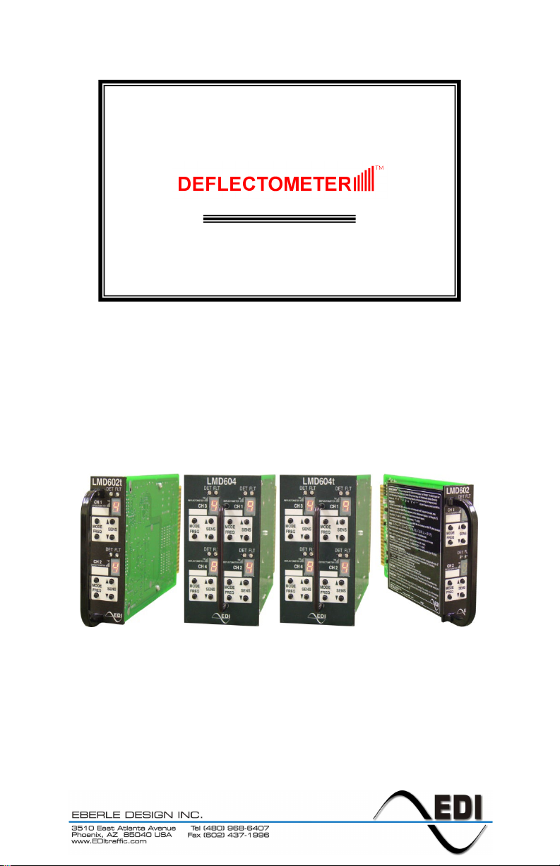
Inductive Loop Monitor
Operations Manual
THIS MANUAL CONTAINS TECHNICAL INFORMATION FOR THE
LMD602, LMD602T, LMD604, and LMD604T SERIES INDUCTIVE LOOP MONITOR.
REVISION: MARCH 2012
pn 888-060X-001

THE LMD602 AND LMD604 SERIES IS DESIGNED AND MANUFACTURED
EDI IS CERTIFIED TO ISO 9001:2008 QUALITY SYSTEMS STANDARDS.
INFORMATION CONTAINED HEREIN IS PROPRIETARY TECHNICAL INFORMATION
OF EBERLE DESIGN INC. PUBLICATION, REPRODUCTION OR USE IN WHOLE OR
PART IS NOT PERMITTED EXCEPT UNDER TERMS AGREED UPON IN WRITING.
DEFLECTOMETER IS A TRADEMARK OF EBERLE DESIGN
IN THE USA BY EBERLE DESIGN INC.
PHOENIX, ARIZONA
U.S. PATENT NO. 7,855,893
© COPYRIGHT 2012 EDI

Table of Contents
Section 1 GENERAL ............................................................................................................... 1
1.1 Description.................................................................................................................... 1
1.2 Overview ....................................................................................................................... 1
1.3 DEFLECTOMETER® Feature ..................................................................................... 1
Section 2 Installation and Adjustments ............................................................................... 3
2.1 Set the Sensitivity Level ............................................................................................... 3
2.1.1 Adjusting Sensitivity Using the DEFLECTOMETER (Recommended) ............ 3
2.1.2 Adjusting Sensitivity Directly .............................................................................. 3
2.1.3 Dynamic DEFLECTOMETER Display Operation .............................................. 4
2.2 Set the Operational Mode ............................................................................................ 4
2.2.1 Output Call Test.................................................................................................. 4
2.2.2 Shor t Presence Mode (S) ................................................................................... 4
2.2.3 L on g Pr es ence Mod e (L) .................................................................................... 4
2.2.4 Pulse Mode (P) ................................................................................................... 4
2.2.5 Call Mode (C) ..................................................................................................... 5
2.2.6 Off Mode (-) ........................................................................................................ 5
2.3 Set the Frequency ........................................................................................................ 5
2.3.1 Dis pl a yi ng the Loop Fr equ ency ......................................................................... 5
2.4 Set the Delay and Extend Timing (LMD602T and LMD604T Only) ........................... 5
2.4.1 Delay Timing ....................................................................................................... 5
2.4.2 Extend Timing ..................................................................................................... 5
2.4.2.1 Extend Always (default) ............................................................................ 6
2.4.2.2 Extend on Green (EOG) ........................................................................... 6
2.4.3 Timer Control Inputs ........................................................................................... 6
2.5 Miscellaneous............................................................................................................... 6
2.5.1 Channel Off......................................................................................................... 6
2.5.2 Retune or Reset a Channel ............................................................................... 6
2.5.3 Factory Default Settings ..................................................................................... 6
2.6 Loop Fault Monitoring .................................................................................................. 6
2.6.1 Current Fault ....................................................................................................... 7
2.6.2 Pr evi ous Fault ..................................................................................................... 7
Section 3 Loop Installation .................................................................................................... 8
Section 4 Specifications ...................................................................................................... 10
4.1 Mechanical ................................................................................................................. 10
4.2 Environmental ............................................................................................................ 10
4.3 Electrical ..................................................................................................................... 10
4.4 Tuning ......................................................................................................................... 10
4.4.1 Loop Inductance (Tu ni ng) R ange .................................................................... 10
4.4.2 Environmental Tracking ................................................................................... 10
4.4.3 Grounded Loop Operation ............................................................................... 10
4.4.4 Lead -in Length.................................................................................................. 10
4.5 Loop Input (Lightning Protection) .............................................................................. 10
4.6 Response Timing ....................................................................................................... 11
4.6.1 LMD 6 02 Series Response Timing ................................................................... 11
4.6.2 LMD604 Series Response Timing ................................................................... 11
4.7 LMD602(t) Co nnector Pin Assignments .................................................................... 11
4.8 LMD604(t) Co nnector Pin Assignments .................................................................... 12

LMD602 and LMD 604 Seri es
Why guess when you can know!
vehicle is in the detection zone. This provides feedback that the unit is
Operati ons M an ual
Section 1
GENERAL
1.1 DESCRIPTION
The LMD602 two ch annel an d LMD604 f our ch annel Nema TS-1 r ack moun ted ind uctive
Loop Mon itor with DEFLECTOMETER® S er i es i s b uil t on th e i nt er n a t i on al card format wit h
double-sided 44 pin edge connectors for connection of power, loop inputs and call outp uts .
The units meet or exceed all requirem ents for d etectors as d ef ined in Nema Standard
TS1-1989 (R2005). Each channel has individual controls for setting up sensitivity,
operati onal mode and frequenc y on the fr ont panel. T wo high inte nsity front panel LEDs
indicate vehicle detect ion, timing operati on and f ault monitor ing status f or each c hannel.
Call out puts ar e available in either r el a y or opt ically-isolated solid-state transistor form.
Model Channels Features
LMD602 Two Channel
LMD602-R Two Channel Relay Outputs
LMD602T Two Channel Delay and Extension Timing
LMD602T-R Two Channel Delay and Extension Timin g, Relay Outputs
LMD604 Four Channel
LMD604T Four Channel Delay and Extension Timin g
1.2 OVERVIEW
A dyna m ic Overvie w of the LMD opera tion which in c ludes an LMD Simulator is availabl e on
the EDI Web Site;
www.EDItraffic.com.
1.3 DEFLECTOMETER® FEATURE
The LMD Series Loop Mon itor introd uc es a c oncept t o th e induc tiv e loop d et ector field that
revoluti onizes the pr ocess of installing and programming a loop det ecto r. Th e new user
int erf ac e of t he LMD Series provides the feedback necessary to the signal technician to
quickly and accurately program the parameters of the detector exactly to the loop plus leadin system characteristics.
The DEFLECTOMETER displ ay sh ows t he r elat ive s tr ength of the c all whil e a
optimal l y tun ed to detect veh ic l es of all sizes.
Settin g t he s ensit ivit y lev el of t h e det ector c an be easil y d one in one step with
a “typical” vehicle parked in the detection zone. The DEFLECTOMETER
display updates dynamicall y as the sensi tivity level is chang ed. See secti on
2.1.1.
The simple push-button interface is intuitive and eliminates many of the
Loop diagnostic capabilities incorporated within the LMD Series Lo op Monitor enable the
detecti on of short or open circuit loops and sudden ch anges of induct ance exceedin g 25
Eberle Design Inc. Page 1
reliability pro blems found with tiny DIP switches of conventional detectors.
Operational mode, Frequency, and Sensitivity are all programmed and
displ ayed using t he push-but ton interf ace. Setti ngs are st ored in n on-volatile
memory.
 Loading...