

Eberle Design LMA-1200-120, LMA-1200 DEFLECTOMETER Series, LMA-1200-LV, LMA-1200-240, LMA-1200S-120 Operating Instructions Manual
...
Operating Instructions
LMA-1200 “
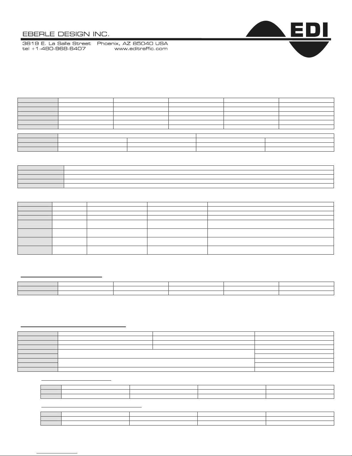
1. Connect to proper source voltage
Verify source voltage before applying power. The “Pin Assignment” side label indicates the input power required for each model and indicates either Fail Safe operation
or Fail Secure operation.
MODELS 12 VDC to 24 VDC or 24 VAC 120 VAC 240 VAC Fail Safe Fail Secure
LMA-1200-LV
LMA-1200-120
LMA-1200-240
LMA-1200S-LV
LMA-1200S-120
LMA-1200S-240
FAIL SAFE OPERATION FAIL SECURE OPERATION
OUTPUT RELAY POWER FAILURE LOOP FAILURE POWER FAILURE LOOP FAILURE
A CALL Output CALL Output No Output No Output
B No Output No Output No Output No Output
2.
DEFLECTOMETER
STATUS
0, 1, 2, 3, 4, 5, 6, 7, 8, 9 Sensitivity Meter (4, 5 & 6 = Optimum Sensitivity Setting for Loop & Lead-in Network)
d 2-Second Delay Timing
E 0, 2, 5 or 10 Second Extension Timing
F Current “Real Time” Loop Failure
●
●
Indications
3. LED Indications
STATUS POWER LED OUTPUT A LED OUTPUT B LED LOOP FAULT LED
OFF No Power Output OFF Output OFF Loop Good
ON Normal Power Output ON Output ON N/A
2 Hz Flash N/A 2-Second Delay Timing 2-Second Delay Timing N/A
4 Hz Flash N/A 0, 2, 5, or 10 Second
1 Flash Insufficient Line
2 Flashes N/A “Real Time” Shorted Loop “Real Time” Shorted Loop “Real Time” Shorted Loop if Outputs A & B are flashing.
3 Flashes N/A “Real Time” 25% Inductance
4. Rear Panel DIP Switches and Rotary Switch
2-Position DIP Switch – Loop Frequency
SWITCH LO MEDIUM – LO MEDIUM – HIGH HIGH FACTORY DEFAULT
1 ON OFF ON OFF OFF
2 ON ON OFF OFF OFF
Loop Frequency (DIPS 1 & 2) is controlled by the rear panel 2-Position DIP switch. On occasion, loops are placed in close proximity; it is necessary to select a different
frequency level for each loop to avoid loop interference (crosstalk). Four (4) frequencies are selectable, HIGH being the factory default. Press reset after changing sensitivity
setting.
8-Position DIP Switch - Detector Parameter Options
SWITCH ON OFF FACTORY DEFAULT
1 Sensitivity Boost No Sensitivity Boost OFF
2 Output A – Limited Presence Output A – Infinite Presence OFF
3 2-Second Delay Timing No 2-Second Delay Timing OFF
4 OFF
5
6 OFF
7
8 Reserved N/A
Extension Timing (Switches 4 & 5)
SWITCH 0-Seconds 2-Seconds 5-Seconds 10-Seconds
Output “B” Relay Configurations (Switches 6 & 7)
SWITCH Pulse On Entry Pulse On Exit Presence (Duplicates Output A) Fault Output
Power
4 0FF ON OFF ON
5 0FF OFF ON ON
6 0FF OFF ON ON
7 0FF ON OFF ON
Single Channel – Dual Output – Inductive Loop Vehicle Detectors
●
●
Extension Timing
“Real Time” Open Loop “Real Time” Open Loop “Real Time” Open Loop if Outputs A & B are flashing.
Change
See “Extension Timing” Table Below (Switches 4 & 5)
See “Output B Relay Configurations” Table Below (Switches 6 & 7)
DEFLECTOMETER
DEFLECTOMETER
0, 2, 5, or 10 Second
Extension Timing
“Real Time” 25% Inductance
Change
” Series
●
● ●
●
“Prior” Open Loop if Outputs A & B are not flashing.
“Prior” Shorted Loop if Outputs A & B are not flashing.
“Real Time” 25% Change In Inductance if Outputs A & B are flashing.
“Prior” 25% Change In Inductance if Outputs A & B are not flashing.
●
N/A
OFF
OFF
●
●
●
Rev. B – 09/18/03

Operating Instructions
LMA-1200 “
4. Rear Panel DIP Switches and Rotary Switch (
Sensitivity Boost (DIP 1): When ON will increase sensitivity only during the CALL Output period without changing the sensitivity of an vacant loop. When a vehicle enters
the loop, the detector sensitivity is boosted to a higher level than the vacant loop setting. The boosted sensitivity remains throughout the CALL Output period. When the
vehicle leaves the loop, the sensitivity returns to the vacant loop setting. This feature helps prevent dropouts during the passage of high bed vehicles and is exceptionally
useful in sliding gate situations.
Output “A” Modes (DIP 2): When ON (Limited Presence Mode), the presence CALL Output hold time is between 5 minutes minimum and 3 hours maximum. When OFF
(Infinite Presence Mode), the presence CALL Output hold time will always be maintained as long as a vehicle is located over the loop zone and power is not removed for more
than approximately 10 seconds (4 seconds on low voltage models). Hold time depends on loop geometry; number of wire turns in the loop, vehicle size, and position of the
vehicle relative to the loop zone.
2-Second Output Delay (DIP 3): When ON outputs A & B will be delayed for a period of 2 seconds after a vehicle has entered the loop zone. If the vehicle does not
remain in the loop zone for the full 2 seconds the delay timer will terminate and no CALL Output will be produced.
0, 2, 5, & 10-Second Output Extension (DIPS 4 & 5): Utilizing the “Extension Timing” DIP switch table on the front page or the table located on the side of the
detector, Output A can be selected to hold a CALL output for either 2, 5 or 10 seconds after the vehicle has left the loop zone. This feature does not affect output B.
Output “B” Modes (DIPS 6 & 7): Utilizing the “Output B Relay Configurations” DIP switch table on the front page or the table located on the side of the detector, four (4)
modes of operation are selectable; Presence (same as Output “A”), Pulse on Entry, Pulse on Exit, or Loop Fault.
In the Presence Mode
enters the loop zone. In the Pulse on Exit Mode
Mode, Output B will output a “Loop Fault” signal only when a loop fault condition exists. If the loop fault self-heals, Output Relay B will assume the “No Fault”
output state.
10-Position Rotary Switch - Sensitivity
Ten (10) levels of sensitivity are selectable (0 through 9). 0 being lowest and 9 being highest, with normal (factory default) being 4.
The front panel DEFLECTOMETER (7-segment LED) aids in setting the detector to the proper sensitivity level to help insure the detection of all vehicles, including motorcycles
and high bed vehicles. This feature is a fantastic aid to all system installers who usually guess what level of sensitivity to set. For typical vehicles (mid-size) utilizing typical
roadway loops, when the number 4, 5, or 6 is displayed on the DEFLECTOMETER during the DETECT (Output) period then the sensitivity is set correctly. DEFLECTOMETER
reading “5” would be most optimum. Examples of utilizing the DEFLECTOMETER are shown below:
If DEFLECTOMETER reading “7” is displayed during the CALL Output state, then lower the sensitivity setting two (2) levels so the DEFLECTOMETER would now
read “5” (DEFLECTOMETER reading “7” – 2 sensitivity levels = DEFLECTOMETER reading “5”.
If DEFLECTOMETER reading “2” is displayed during the CALL Output state, then raise the sensitivity setting three (3) levels so the DEFLECTOMETER would now
read “5” (DEFLECTOMETER reading “2” + 3 sensitivity levels = DEFLECTOMETER reading “5”.
NOTE: THE SENSITIVITY SWITCH DYNAMICALLY UPDATES AFTER EACH SWITCH POSITION CHANGE, ALLOWING YOU TO SWITCH SENSITIVITY SETTINGS
WHILE THE VEHICLE IS IN THE LOOP ZONE.
5. Additional Features & Benefits
Output A & B LED Indicators: Separate relay output LED indicators allow users to verify and confirm that both output relays are correctly working for the configurations
selected.
Reset: The detector can be manually reset by pressing the front panel RESET button or momentarily interrupting power. Note: The detector must be reset after selecting
any new switch parameters.
Loop Fault Memory: Previous loop faults are stored in non-volatile (internal) memory. If power is interrupted, for any length of time, the detector will not loose the last
loop condition status. When power is restored to the detector, the yellow FAULT LED will automatically
Change In Inductance, or No Loop Problem – See Table on the front page). Momentarily pressing the front panel RESET button will reset the loop fault indicator and the
detector. Should you want to review the last loop condition after the detector has been reset, simply PRESS and HOLD the reset button and after 2 seconds the LOOP FAULT
indicator will start to indicate the last loop fault condition.
Output “CALL” Memory: A power loss of 10 seconds or less will not drop the vehicle CALL Output. If power is removed from the detector for 10 seconds or less, the
detector will automatically remember if a vehicle is present over the roadway loop. Note: The LMA-1200-LV or LMA-1200S-LV (low voltage) models will hold the CALL Output
for approximately 4 seconds.
Loop Fault Diagnostics: The Loop Fault LED and 7-Segment DEFLECTOMETER indicate if the detector is within the specified Loop Inductance Range. The detector is able
to detect Open Loops, Shorted Loops, or sudden changes in loop inductance exceeding 25% of the nominal inductance. If a Loop Fault is detected, the OUTPUT and FAULT
LED’s continuously emit a sequence of flashes (See LED Indications table on the front page). Additionally, the 7-Segment DEFLECTOMETER displays the letter “F” indicating a
current loop fault condition.
If an Open or Shorted fault condition self heals, the OUTPUT LED’s and the 7-Segment DEFLECTOMETER will return to normal operation. The FAULT LED will continue to
flash with the sequence signifying the type of loop fault that was last detected. In the case of the excessive inductance change fault, the unit will retune to the new
inductance after a period of two seconds and continue operation. The fault condition will be indicated by the flash sequence of the fault LED. Pressing the “RESET” button
will clear the flash sequence from the LOOP FAULT LED. See “Loop Fault Memory” above for additional information.
Lead-in Lengths: The detector will operate with lead-in lengths up to 5,000 feet with appropriate loops and proper lead-in cable.
Operating Temperature: -30
Pin Assignment (Connections):
Model LMA-1200-LV Model LMA-1200-120 and LMA-1200-240
Pin Function
1 12 VDC to 24 VDC / 24 VAC (+) 1 AC Line
2 DC Ground / 24 VAC (-) 2 AC Neutral
3 Output Relay “B”, Normally Open (Closes for DETECT) 3 Output Relay “B”, Normally Open (Closes for DETECT)
4 No Connection 4 No Connection
5 Output Relay “A”, Common 5 Output Relay “A”, Common
6 Output Relay “A”, Normally Open (Closes for DETECT) 6 Output Relay “A”, Normally Open (Closes for DETECT)
7 Loop Input 7 Loop Input
8 Loop Input 8 Loop Input
9 Output Relay “B”, Common 9 Output Relay “B”, Common
10 Output Relay “A”, Normally Closed (Opens for DETECT) 10 Output Relay “A”, Normally Closed (Opens for DETECT)
11 Output Relay “B”, Normally Closed (Opens for DETECT) 11 Output Relay “B”, Normally Closed (Opens for DETECT)
, Output B duplicates the Output A selection. In the Pulse on Entry Mode, Output B provides a 250-millisecond pulse when a vehicle
o
F to 165oF (-34oC to +74oC).
Single Channel – Dual Output – Inductive Loop Vehicle Detectors
Continued
, Output B provides a 250-millisecond pulse when a vehicle exits the loop zone. When in the Loop Fault
DEFLECTOMETER
” Series
)
indicate the last loop status condition (Open Loop, Shorted Loop, 25%
Pin Function
Rev. B – 09/18/03
 Loading...