

THIS MANUAL CONTAINS TECHNICAL INFORMATION FOR THE AUXILIARY DISPLAY
UNIT FIRMWARE VERSION 0110
MANUAL REVISION: JULY 2010
pn 888-0217-001
Auxiliary Display Unit
(ADU)
Operations Manual

THE AUXILIARY DISPLAY UNIT (ADU) IS DESIGNED AND MANUFACTURED IN THE
USA BY EBERLE DESIGN INC.
PHOENIX, ARIZONA
EDI IS CERTIFIED TO ISO 9001:2008 QUALITY SYSTEMS STANDARDS.
SMARTMONITOR AND MONITORKEY ARE TRADEMARKS OF EB ER LE DESIGN INC.
MANUFACTURED UNDER U.S. PATENT 7,246,037.
INFORMATION CONTAINED HEREIN IS PROPRIETARY TECHNICAL INFORMATION
OF EBERLE DESIGN INC. REPRODUCTION OR USE IN WHOLE OR PART IS NOT
PERMITTED EXCEPT UNDER TERMS AGREED UPON IN WRITING.
© COPYRIGHT 2010 EDI.

Section 1 General.................................................................................................................... 1
Tabl e of Cont ent s
1.1 Overview ....................................................................................................................... 1
1.2 Displays ........................................................................................................................ 1
1.3 Context Sensitive Help System ................................................................................... 1
1.4 SmartMonitor ® Diagnostic Wizard .............................................................................. 1
Section 2 Front Pane l Des cript ion ........................................................................................ 2
2.1 Displays ........................................................................................................................ 2
2.1.1 Channel Status Display ...................................................................................... 2
2.1.2 Main Status Display............................................................................................ 2
2.1.3 SB#3 RxDATA Indicator..................................................................................... 2
2.1.4 Display LED Test ................................................................................................ 2
2.2 Front Panel Buttons ..................................................................................................... 2
2.2.1 Next Button ......................................................................................................... 2
2.2.2 Back Button ........................................................................................................ 2
2.2.3 S el ect But ton ...................................................................................................... 2
2.2.4 Exit Button .......................................................................................................... 3
2.2.5 Help Button ......................................................................................................... 3
2.2.5.1 Invoking the Diagnostic Wizard ................................................................ 3
Section 3 Menu Operation ..................................................................................................... 4
3.1 Main Status Menu Map ................................................................................................ 4
3.2 Top L ev el M en u ........................................................................................................... 4
3.2.1 St at us .................................................................................................................. 5
3.2.2 M en u ................................................................................................................... 5
3.2.2.1 View Logs ................................................................................................. 5
3.2.2.2 View Configuration ................................................................................... 5
3.2.2.3 Clear Logs ................................................................................................. 5
3.2.2.4 View Firmware Level ................................................................................ 5
Section 4 Diagn o st i c Wizard ................................................................................................. 6
4.1 Launching the Diagnostic Wizard ................................................................................ 6
4.2 Diagnostic Wizard Steps .............................................................................................. 6
4.2.1 Concise Display Step ......................................................................................... 6
4.2.2 F aulty Signal Id ent if ication Step ........................................................................ 6
4.2.3 Trouble Shooting Tips Step ............................................................................... 6
Section 5 Trouble Shooting ................................................................................................... 7
5.1 Trouble Check Points ................................................................................................... 7
5.1.1 AC Line Power.................................................................................................... 7
5.1.2 Serial Bus #3 ...................................................................................................... 7
5.2 ADU Error Messages ................................................................................................... 7
5.2.1 Communication Error ......................................................................................... 7
5.3 Technical Support ........................................................................................................ 7
Section 6 SPECIFICATIONS .................................................................................................. 8
6.1 SB #3 Communication Port ......................................................................................... 8
6.2 Mechanical ................................................................................................................... 8
6.3 Environmental .............................................................................................................. 8
6.4 Electrical ....................................................................................................................... 8

Auxiliary Display Unit (ADU)
Operat i ons M an u al
Eberle Des ign Inc. Page 1
Section 1
General
1.1 OVERVIEW
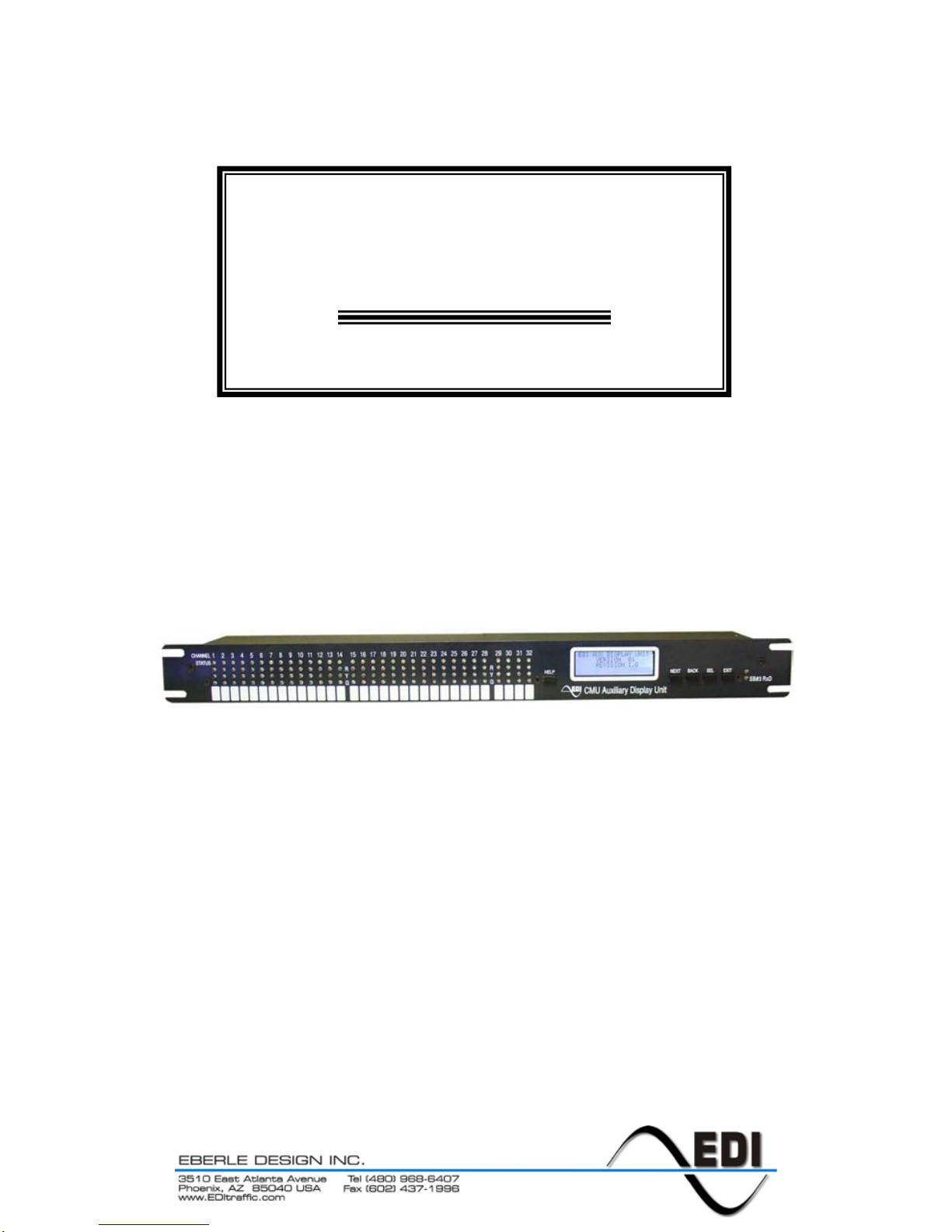
The Eberle Design Auxiliary Display Unit (ADU) is a display module that provides an
enhanced user interfac e for th e ITS C abinet M oni t or U n it ( CMU-212) system. T h e Auxiliary
Dis p lay Unit is i ntend ed to mount int o a 1U sp ac e of th e 19 inch r ack of an ITS C abinet.
The Auxiliary Display Unit meets with or exceeds all specifications outlined in the
ASHTO/ITE/NEMA Intel ligent Tr ansport ation Sy stem (IT S) Standar d Specif ication f or
Roadside Cabinets Version 01.02.17b document.
1.2 DISPLAYS
The Aux iliary Dis play Un it provi des a Red, Yellow, and Green st atus LED indicator along
with a Blu e LED indic ator f or fault st atus, f or each of the thir ty tw o chann els supp orted b y
the CMU-212. This LED Channel Status display provides a full view of the intersection
status.
The Aux ilia ry Disp lay Un it al s o provid es a Liqui d Cr yst al (LCD ) b ase d men u dr iven dis play
that provid es det ailed status inf ormati on fr om the CMU-212 along with an interface to the
EDI SmartMonitor® technology.
For further information on the ITS Cabinet Monitor Unit (CMU-212), CMU-212 monitor
functions, and CMU D ata Key parameters ref er to the E berle Design CMU-212 Cabinet
Monitor Unit Operations Manual (pn 888-0212-001).
1.3 CONTEXT SENSITIVE HELP SYSTEM
The built-in Help s ystem provid es operati onal guidanc e as well as trouble sh ooting advic e
to both the novice and expert technician. The front panel HELP button presents the
requested information on the main LCD depending on the display page and context
currently selected.
1.4 SMARTMONITOR
®
DI AGN OS TIC WI ZAR D
The built-in Di agnostic W izard (s ee S ect ion 4) is an integral part of the Help System th at
provides detailed diagnostic information regarding the fault being analyzed. The Wizard
provides a concise view of the signal states involved in the fault, pinpoints faulty signal
inputs, and provides guidance on how the technician should isolate the cause of the
malfunction.
The CMU-212 monitor must be programmed with a firmware version that
supports the operation of the Auxiliary Display Unit (ADU). Consult the
factory for the firmware version information for the installed CMU-212 model.

Auxiliary Display Unit (ADU)
Operat i ons M an u al
Eberle Des ign Inc. Page 2
Section 2
Front Panel Description
2.1 DISPLAYS
2.1.1 CHANNEL STATUS DISPLAY
Thirt y two Red , Yellow, and Gr een LED indicators are provided by the Auxiliary Display
Unit to display the com plete inters ection st atus of the field signal inputs t o the CMU-212
monitor. If the monitor is oper ating nor mall y without a fault con diti on presen t, the cu rrentl y
active RYG field input signal states will be displayed.
When th e CMU-212 monitor is in the fault mode, all channels that were involved in the fault
will be indicated by the Blue LED indicators.
2.1.2 MAIN S TATUS DISPL AY
The Mai n Stat us Dis play (LCD) of t h e A ux il iar y Dis p la y U n it is us ed t o displa y the cur rent
status of the CMU-212 monit or and n avigate the menu levels (see Section 3). W hen the
CMU-212 monitor is not in the fault mode, the Main Status display will show current monitor
status. When the CMU-212 m onitor is in the fault m ode, the Mai n S tatus dis play wi ll s how
the latched CMU-212 monitor status at the time of the fault.
2.1.3 SB#3 RXDATA INDICATOR
The SB#3 RxDATA LED indicator will be pulsed each time that a SDLC message is
correctly received from the CMU-212 monitor via Serial Bus #3. This indicator pulses
rapidly dur ing n ormal operat ion. If the Aux iliary D isplay Unit is n ot recei ving d ata fr om th e
CMU-212 monitor then the Main Status Display will show an error message “NO SB3
COMM from CMU ” on li n e #4 .
2.1.4 DISP LAY LED TEST
The monit or will illu min ate all f r ont pan el LED and LCD i n dic ators f or 500 ms wh en a R eset
comm and is iss ued by t he fr ont p anel RESE T butt on or EXT ERNAL RE SET in put of t he
CMU-212. This function provides a means to check the operation of all front panel
indicators.
2.2 F R ONT P ANEL BUTTONS
Menu navigation is detailed in Section 3.
2.2.1 NEXT BUTTON
The NEXT navigati on button is used to mov e to the next display window in a le vel of the
menu (down), mov e the cursor, or inc rement th e parameter (chan nel, input, l og number,
etc) of the curr en t dis play f unct i on. S ome d ispl ay mod es will in dic at e that th e NE XT but t on
affects a parameter by displaying a “<n>” symbol. Additional scr eens in a sequenc e are
indicate d by the “↓” symbol displayed in the lower right corner of the Main Status display.
2.2.2 BACK BUTTON
The BACK navi gation butt on is used t o move to t he previous display wi ndow in a level of
the men u (up), move the cursor backwards, or decrement the par ameter (channel , input,
log number, etc) of the current display function.
2.2.3 SELECT B UTT ON
The SEL ECT n avigation button is used onc e the curs or () has been placed next to the
desired parameter to enter or tog gle the selection. Some display mod es will indicate that
the SELECT button affects a parameter by displaying a “<s>” symbol.

Auxiliary Display Unit (ADU)
Operat i ons M an u al
Eberle Des ign Inc. Page 3
2.2.4 EXIT BUTTON
The EXIT navigati on button is us ed to exit fr om a display mod e and sets t he new displ ay
mode on e level b ack up the n avig ation tr ee. Cont inue to pr ess th e EXIT unti l the top l evel
menu item is reached.
2.2.5 HELP BUTTON
The HELP butt on activates the context s ensitive H elp system. W hen the HELP bu tton is
press ed, th e disp lay will t empor aril y ent er th e Hel p syst em mod e an d disp lay a scr een t hat
offers an explanation of the current menu item. Pressing the HELP button or the NEXT
butt on will displ ay addit ional sc reens in the s equenc e if avail able. Addit ional scr eens in a
displ ay s equenc e are i ndic ated by t h e “↓” symbol displayed in the lower right c orner of the
Main St atus dis p lay.
The EXIT button is pressed to exit the Help system mode. The display mode will then
return to the last s el ect ed m enu disp l ay level.
2.2.5.1 INVOKING THE DIAGNOSTIC WIZARD
The HELP button automatically activates the Diagnostic Wizard (see Error! Reference
source not foun d.) wh en the dis pl ay m ode is c urr ently at t h e top level menu AN D t he unit
is in the f ault s tate. W hen the H ELP butt on is pr ess ed, th e dis play will enter t he Di agn ostic
Wizard mode and display a sequence of screens that help diagnose the current fault.
Pressing the HELP button or the NEXT button will display additional screens in the
sequenc e if available. Additional screens in a display sequenc e are indicated by the “↓”
symbol displayed in the lower right corner of the Main Status display.
The HELP button also automatically activates the Diagnostic Wizard when the display
mode is set to the Display Previous Failure (PF) log menu item (see 3.2.2.1).
The E XIT bu tton is pressed to exit the Di ag n ost ic Wiz ard m od e. T h e dis pl ay mode will th en
return to the last s el ect ed displ ay l ev el.

Auxiliary Display Unit (ADU)
Operat i ons M an u al
Eberle Des ign Inc. Page 4
Section 3
Menu Operation
3.1 MAIN STATUS MENU MAP
The m enu dr iven user int erf ace foll ows th e map s hown below. At th e top level, t he NE XT
butt on selects whether C urrent St atus det ails or th e main Men u select ions are d isplayed .
The NEXT b utton is used t o s c roll thr ough the various selec tions t hat each m enu lev el ma y
provi de. Pr ess ing the SE LEC T b utt on wil l i nvok e th e func tion th at th e cur s or () p oint s t o.
At any time the EXIT or BACK button may be pressed to b ac k out of a m enu s el ect i on.
3.2 TOP LEVEL MENU
The Top Level Status menu displays the current monitor status, consisting of the fault state,
time and d at e, and t he f ield s ign al stat es. T his is the d efault d is play foll owin g a Res et. T he
Diagnostic Wizard (see Section 4) is automatically invoked when the HELP button is
pressed at this level if the CMU-212 moni tor is currently in the fault state.
Top Lev el
Status
Status
<Fault>
Signal
Voltages
(FC
Status)
(RP
Status)
Cabinet
Voltages
<No Fault>
Signal
Voltages
Cabinet
Voltages
Menu
View L ogs
Previous
Fail Log
Reset Log
AC Lin e
Log
Clear Logs
All Logs
Previous
Fail Log
Reset Log
AC Lin e
Log
Config
Change
Log
View
Config
Unit
Options
AMU
Config
12V
Monitor
SB1
Address
Datakey
Format
Datatkey
Checksum
ECcom ID
Monitor
ID
User ID
Permissives
Lack of
Signal
(LOS)
LOS Da rk
Maps
Multiple
Enable
GY YR GR
Clearance
Y
Clearance
Y+R
Clearance
Field
Check
Enable
Yellow
Disable
Current
Sense
Virtual
Channels
ECcom
Port
Flashing
Yellow
Arrow
Firmware
Level

Auxiliary Display Unit (ADU)
Operat i ons M an u al
Eberle Des ign Inc. Page 5
3.2.1 STATUS
Pressing the SELECT button from the top level provides further details regarding the
current state including Field Check status (if applicable), Recurrent Pulse Status (if
applicable), Field Voltages, and Cabinet Voltages. This status may be current (no fault
state) or the latched status at the time of the fault (fault state).
3.2.2 MENU
Press ing the N EXT b utton f ollowed by th e SELECT button f rom t he top le vel pr ovides the
main Menu structure for selecting the following functions:
3.2.2.1 VIEW LOGS
This menu category p rovides a review of :
Previous Failure (PF) log
AC Line (AC) event log
Monitor Reset (MR) log
Events are stored with #1 being the newest event in the log. Pressing the NEXT button will
displ ay the event s f rom n ewes t t o old est ( #1 … #n). Pr ess ing t he BACK butt on will disp lay
the event s from oldes t t o n ew es t (#n … #1) .
The Diagnostic Wizard is automatically invoked when the HELP button is pressed while
reviewing any of the Previous Failure (PF) logs.
3.2.2.2 VIEW CO NFIGURAT I ON
This m enu categ ory provid es a means t o review and/or s et configu ration p arameters that
are programmed into the Data Key. Note that to change a programming parameter, the
Data Key must be reprogrammed. Refer to the Eberle Design MonitorKey
®
Data Key
Programming Tool Operations Manual (pn 888-1212-001).
3.2.2.3 CLEAR LOGS
This menu category provides a means to clear the following logs:
Previous Failure (PF) log
AC Line (AC) event log
Monitor Reset (MR) log
Configuration (CF) log
The ALL selection will clear all four event logs.
3.2.2.4 VIEW FIRMWARE LEVEL
This menu item provides the CMU-2 1 2 m oni t or f ir m w ar e l evel .
The Aux iliar y D is play U n it f irmw ar e l ev el can b e ob t ained by oper atin g the Auxiliar y Display
Unit wit hout an SB#3 c on n ection to t he C MU-212 moni tor. When S B#3 c ommun ic ati ons is
not op erati ng, t he Auxilia ry D isp lay Un it wil l def ault to a sc reen on th e M ain St atus D isp lay
the shows the installed firmware level.

Auxiliary Display Unit (ADU)
Operat i ons M an u al
Eberle Des ign Inc. Page 6
Section 4
Diagnostic Wizard
The buil t-in Di agn ostic W izard is an int egr al part of t he H elp S yst em th at pr ovid es d etail ed
diagn ostic inf ormation r egardi ng the faul t being analyzed . The Wizar d provid es a concis e
view of the signals involved in the fault, pinpoints faulty signal inputs, and provides
guidance on is ol at i ng th e c ause of the m alfunct i on .
Note that the full benefit of the Diagnostic W izar d will n ot be obt ai ned un less the C MU-212
has been pr ogr am m ed with the Field C h ec k Enable parameters set. T he ED I Set up Wizard
of the MonitorKey
®
Da ta Key Progra mming Too l c an be used to pr ogram the Fi eld Check
Enable function automatically. Refer to the Eberle Design MonitorKey
®
Data Key
Programming Tool Operations Manual (pn 888-1212-001).
4.1 LAUNCHING THE DIAGNOSTIC WIZARD
The Di agnost ic W izard is aut omatic ally in voked when the CMU-212 monit or is in th e fault
mode and th e H E LP bu tton is press ed w hil e the Main Status dis play is at the top level. It is
also automaticall y i n vok ed wh en th e Auxiliary Display Unit is in the Previous Fail (PF) event
log display mode and the HELP button is pressed.
4.2 DIAGNOSTIC WIZARD STEPS
Press in g the H ELP b utton or t he N E XT b utton w il l sequ ence th e disp l ay thr oug h t hi s seri es
of steps. At any point the EXIT button will return the display back to the normal display
mode.
4.2.1 CONCISE DISPLAY STEP
The first step of the Diagnostic Wizard provides a simple definition of the fault type
detect ed. It als o filters th e Channel St atus dis play to a c oncise vi ew of only th e ch annels
ac tually invo lv ed in the fault.
Press the HELP or NEXT button to proceed to the next Diagnostic Wizard step.
4.2.2 FAULTY SIGNAL IDENTIFICATION STEP
The next step(s) pinpoint known faulty signals. This function relies on the proper
progr am mi ng of t h e Fi eld Ch ec k En able p ar am et er s i n the C MU -2 12 Data K ey. This s tep is
the heart of the Diagnos tic W izard. It identif ies first whether the fault condition was caus ed
by t he Controller Unit or by a malf unction of the load b ay or field wi ring and loads. If th e
malfunction was caus ed by a malfunction of the load bay or field wiring and loads, the
“fault y” in puts of each ch an nel ar e direc tly identified along wit h t h e proper st ate.
Press the HELP or NEXT button to proceed to the next Diagnostic Wizard step.
4.2.3 TROUBLE SHOOTING TIPS STEP
The last step off ers the tech nician s everal sugg estions to investigate f or th e cau se of t he
malfunction.
If Field Check is not enabled f or a signal that is part of the concise display fault
status then the D iagnostic Wizard wil l identify the input(s) as “not Field Checked”.
The f ull benefit of the Diagnostic W izard will not be obtained unless the CMU-212
has been fully progr am m ed w ith the F i eld Ch ec k En able parameters c orrec t l y s et.

Auxiliary Display Unit (ADU)
Operat i ons M an u al
Eberle Des ign Inc. Page 7
Section 5
Trouble Shooting
5.1 TROUBLE CHECK POINTS
5.1.1 AC LINE PO WE R
W hen AC Line p ower is applied t he Aux iliary D isplay Unit LC D display will al ways show a
message. If no message is displayed check that the AC Line cord is plugged in and that the
AC Line fuse is intact.
The AC L ine fus e holder is located on the rear of the unit next t o the AC Line cord and
r equ i res a 1A SB fuse.
5.1.2 SERI AL BUS #3
W hen com munic ations is establis hed b etween t he CMU-21 2 moni tor and A ux iliary D isp lay
Unit, th en the “SB# 3 RxD” indic ator on th e Auxiliary D is pla y U nit front panel will regular ly
flash. If th e Auxiliary D isp lay U n it is not communic ating with the CMU-21 2 m onitor , t h en t h e
Auxiliary Display Unit LCD display will show an error message stating “NO SB3 COMM
from CMU” on line #4.
1) The SB #3 c able mus t b e conn ected betw een th e Auxilia ry D isplay Un it and the
SB#3 RJ-45 c onnect or in the last Outp ut A s sembly of t h e c abi n et . T his cabl e is a
st a n d ar d C at -5 netw ork c abl e and is th e sam e cab le us ed t o conn ec t the O utput
Assemblies to the PDA.
2) The CMU-212 monitor must be programmed with a firmware version that
supports the operation of the Auxilia ry Display Unit. C onsult the f actory for the
firmware version information for the installed CMU model.
3) Ther e is n o s etu p programmi ng requir ed in the CMU-212 monitor to enable the
Auxiliary Display Unit. If the
5.2 ADU ERROR MESSAGES
5.2.1 COMMUNICATION ERROR
If the Auxiliary Display Unit is not communicating with the CMU-212 monitor, then the
Auxiliary Display Unit LCD display will show an error message stating “NO SB3 COMM
from CMU” on line #4.
5.3 TECHNICAL SUPPORT
Additional technical support may be obtained by contacting Eberle Design Inc.
Eberle Des ign Inc.
3510 E Atlanta Avenue
Phoenix, AZ 85040 USA
Telephone: (480) 96 8-6407
Fax: (602) 437-1996
e-mail:
Web Site:
support@EDItraffic.com
www.EDItraffic.com

Auxiliary Display Unit (ADU)
Operat i ons M an u al
Eberle Des ign Inc. Page 8
Section 6
SPECIFICATIONS
6.1 SB #3 COMMUNICATION PORT
This integrated port provides the EIA-485 d ata p ath to t he CMU-212 Cabi net Mon itor U nit
(CMU) us ing S eri al Bus #3. T h e s i gn a l s ar e Neu tr al Gr ound referenced. A s tand ar d CAT -5
network cable with RJ-45 connector is used. The cable connects from this port to an
unoccupied SB#3 RJ-45 port of th e Ou tp ut A s s em bl y.
Pin
Function
1
Reserved
2
Reserved
3 Neutral (AC- Raw)
4
RxDATA +
5
RxDATA -
6 Neutral (AC- Raw)
7
TxDATA +
8
TxDATA -
6.2 MECHANICAL
Height ......................................................................................................... (1U ) 1.7 inches
Width ............................................................................................................... 19.0 inches
Depth (excluding handle) .................................................................................. 1.5 inches
6.3 ENVIRONMENTAL
Storage Temperature Range ...................................................................... -45 to +85
o
C
Operating Temperature Range ................................................................... -34 to +74
o
C
Humidity Range (non-condensing) ....................................................... 0 to 95% Relative
6.4 ELECTRICAL
AC Operati ng Voltage Minimum ........................................................................... 89 Vac
AC Operati ng Voltage Maximum ........................................................................ 270 Vac
AC Operating Frequency ............................................................................... 45 to 65 Hz
 Loading...