


- 0 -
USER MANUAL
- 2 -
Thank you for purchasing the eBeam Touch. To fully utilize this product, please read
the user manual in detail before use. Be sure to keep the manual in a convenient
location to easily access support whenever needed.
SAFETY PRECAUTIONS
Do not expose the unit to direct sunlight for extended period of time. Do not place
the unit under high temperatures. The power supply is AC100V-240V, 50Hz/60Hz.
Please check and ensure AC source is grounded. Please use the antenna isolator
during installation.
WARNING
Do not attempt to open the cabinet to avoid any electrical shock. Consult your
appliance dealer or local service provider if you have a problem with the unit.
Please do not place any liquids on the unit. Be sure to unplug the power supply
before cleaning. The front of the display panel is protected by reinforced glass,
but can still be damaged if the panel is dropped face down or if the panel is striked
with a hard object. If the front glass is cracked, please be cautious of broken glass.
Please check and ensure AC source is grounded. Please ensure the unit is
mounted on a stable surface. Please be aware of the high voltage inside the unit
when the red light is on.
This lightning flash with arrowhead symbol within an equilateral triangle
is intended to alert the user to the presence of non-insulated
“dangerous voltage” within the product’s enclosure that may be of
sufficient magnitude to constitute a risk of electric shock.
The exclamation point within an equilateral triangle is intended to
alert the user to the presence of important operating and
maintenance instructions in the literature accompanying the
appliance.

- 3 -
Table of Contents
SAFETY PRECAUTIONS .................................................................................................................................. 2
WARNING ..................................................................................................................................................... 2
Outlook of Display ........................................................................................................................................ 4
Open the package .................................................................................................................................... 4
I/O on Front Panel ........................................................................................................................................ 5
I/O on Back Panel ......................................................................................................................................... 5
Attention .................................................................................................................................................. 6
Power Supply ........................................................................................................................................... 6
Battery Installation ....................................................................................................................................... 6
Insert Batteries ........................................................................................................................................ 6
Caution ..................................................................................................................................................... 6
Remote Control Instructions ........................................................................................................................ 7
Remote Control Functions ........................................................................................................................... 7
Main Interface ....................................................................................................................................... 10
System Setting Operation .......................................................................................................................... 12
Picture Menu ......................................................................................................................................... 12
APK File Installation ............................................................................................................................... 15
Computer Ports and Connect Operations (Optional) ................................................................................. 17
Computer Terminals .............................................................................................................................. 17
CAUTION ................................................................................................................................................ 17
Command form: [F6][Command][Set ID][Data][CS][6F] ........................................................................ 18
Recycle ................................................................................................................................................... 18
- 4 -
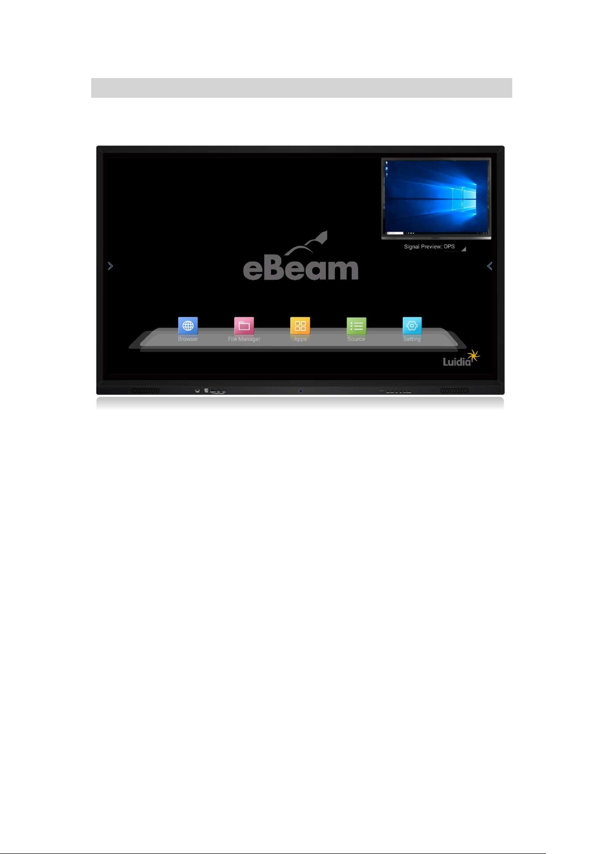
Outlook of Display
Open the package
Front View
Supplied Accessories
⚫ Power cable
⚫ Remote control
⚫ User Manual
⚫ Handwriting pen
⚫ USB cable (Optional)
⚫ HDMI cable (Optional)
⚫ Certificate
⚫ Warranty card
⚫ Tools package
- 5 -
Function Instruction
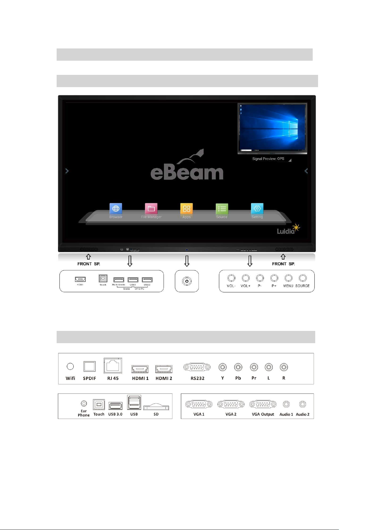
I/O on Front Panel
Function Instruction Power Front Panel Button
I/O on Back Panel
- 6 -
Attention
⚫ Please pay attention to the display terminal function while it is connected to
other equipment.
⚫ Please read this manual carefully if terminal function is not clear.
⚫ Before connecting with other equipment, please power off and make sure the
input and output are connected correctly.
⚫ If the display unit is inactive for a long period of time, please power down, and
disconnect the power plug.
Power Supply
Connect the display’s AC cord to a power outlet (AC110~240V, 50/60HZ). Power on
the panel by pressing the red LED indicator light (standby mode). Press the power
button on the remote control or use the keyboard on the panel. The display unit is
ready to use when the red LED indicator light turns blue. Switch back to standby mode
before powering off.
Battery Installation
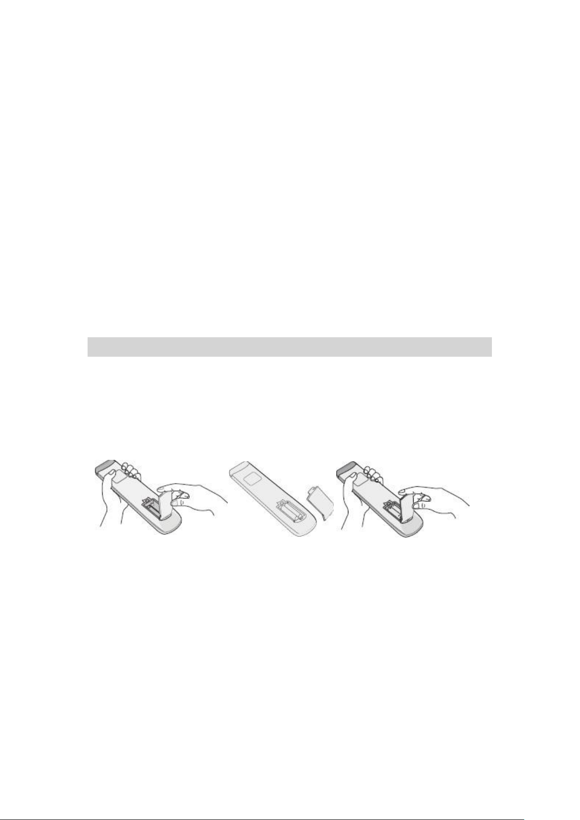
Insert Batteries
1. Remove the cover located on the back of the remote control
2. Insert two “AAA” batteries
3. Place the cover back
Caution
⚫ Do not mix new and old batteries.
⚫ Do not use different types of batteries together (i.e. manganese and alkali ).
⚫ If the barttery is not rechargeable, do not recharge the battery.
⚫ Please remove battery when not in use.
⚫ Please give dead batteries to the recycle department.

- 7 -
Remote Control Instructions
⚫ Do not drop the remote control.
⚫ Avoid applying any physical impact to the remote control.
⚫ Keep the remote control in a cool and dry environment. Any liquid contact may
cause damage or malfunction.
⚫ Replace battery when power is insuffient.
Remote Control Functions

- 8 -
Remote Control Buttons Function Description
1 POWER
Power
2 MUTE
Mute Sound On/Off
3 P-Mode
Change Picture Mode
4 Sound
Change Sound Mode
5 Zoom
Zoom In/Out
6 Sleep
Sleep
7
Reverse
8
Fast forward
9
Previous track
10
Next track
11
Play/Pause
12
Stop the current playback
13 Page ▲
Page Up
14 Page ▼
Page Down
15 HDMI
HDMI Input
16 VGA
VGA Input
17 PC
PC Input
18 Media
Switch to Media Signal
19 Menu
Android Home Page
20 Exit
Exit
21 ▲
Up
22 ◄
Left
23 ▼
Down
24 ►
Right
25 Enter
Enter/Select
26 Back
Previous Page (Android only)
27 Source
Toggle through Input Source
28 VOL+
Increase Volume
29 VOL-
Decrease Volume
30 Windows
OPS Windows
31 Channel+
Channel Up
32 Channel-
Channel Down
33 PC Power
PC Power
34 1
1

- 9 -
35 2
2
36 3
3
37 4
4
38 5
5
39 6
6
40 7
7
41 8
8
42 9
9
43
Freeze Frame
44 0
0
45
Child Lock
NOTE: Functions related to PC will only work if internal PC is installed.
Operating Instruction
Channel Selection
1. Channel up (+) and down (-)
Press (+) to select a higher channel.
Press (-) to select a lower channel.
2. 0-9 keypad
Enter the channel number. Display will change accordingly to channel.
Sound Volume Adjustment
Press the volume +/- to adjust the sound level.The dot will move [ left for Volume
Down ] or move [ right for Volume Up ] .
To mute the sounds, click the mute icon. To close the mute function, click the mute
icon again.

- 10 -
Main Interface
NOTE: Normal display is pictured above.
- 11 -
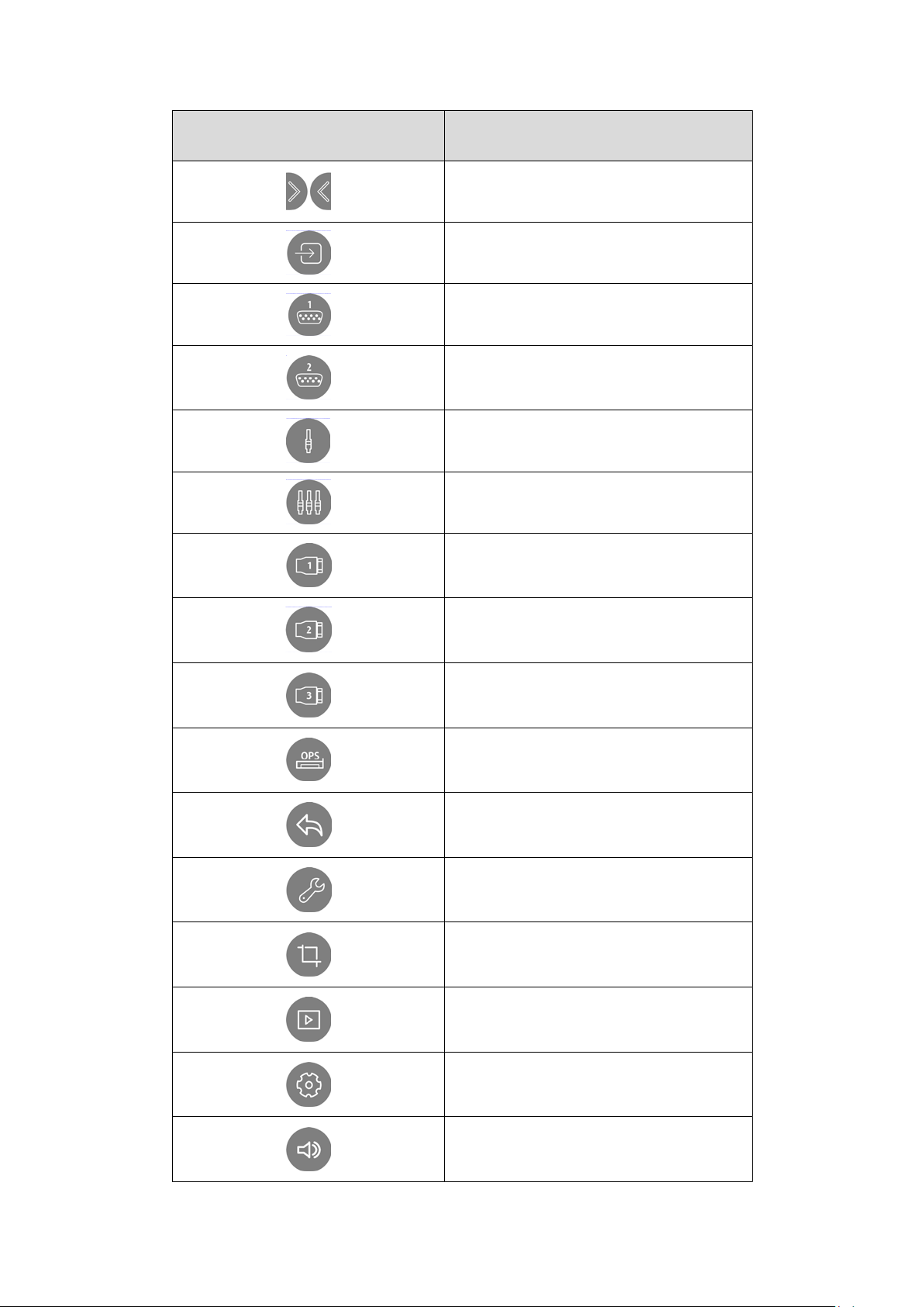
Icon
Function Description
Open / Close Sidebar
Source Selection
VGA 1
VGA 2
CVBS
YPBPR
HDMI 1
HDMI 2
HDMI 3
OPS PC
Back
Toolbar
Screen Shot
Media Browser
System Setting
Volume Adjustment

- 12 -
Open File
Annotation
Recently Opened Apps
Home
System Setting Operation
Press Toolbar to display the System Setting.
Use the “▲/▼” arrows to navigate through the Picture/Sound/Setting/Time menu.
Picture Menu

- 13 -
Sound Menu
Setting Menu

- 14 -
Time Menu
Source Menu

- 15 -
Input Signal Switching Over
Press “Source ” button, showing Source Menu, then use ▲/▼ to navigate each
Source, Press “ENTER” to make your selection.
APK File Installation
1. Insert USB stick or SD card with APK files, open the files in the main page
2. Find SD card or USB external storing disk in the left menu column, open and all files will show
on the right column.

- 16 -
3. Find the APK files in the external saving files, click and install.
Download and Install APK online.
If needed, download and install APK online. Be sure the SD card is inserted into the main board
before downloading APK. You will not be able to download APK files if SD card is not inserted.

- 17 -
Computer Ports and Connect Operations (Optional)
eBeam Touch Panel is equipped with OPS Slot for optional OPS operation. Please
follow the picture below to insert OPS unit into the monitor. Please turn off power
before installing OPS
Computer Terminals
CAUTION
The power and the signals are connected by 80-pin connector.
If removed from the main unit, please check and remove any clogging in
the pin connector before reinserting. It is recommended to keep the
connector clean.
- 18 -
RS232 Com-port Function Setting and Encode Table
RS232 connects with computer or center equipment. Open the RS232 Com-port and
make sure the settings are the same as below.
Port number:COM1(Based on the port number of computer or center control)
Bit rate:
9600
Odd-even verify:
no
Data:
8
Stop bit:
1
The key operation function is the same as the remote control key pad.
Turn on
F6 01 01 01 F9 6F
HDMI1
F6 30 01 0930 6F
Turn off
F6 01 01 00 F9 6F
HDMI2
F6 30 01 0A31 6F
Mute on
F6 02 01 01 FA 6F
CH+
F6 37 01 002E 6F
Mute off
F6 02 01 00 F9 6F
CH-
F6 37 01 012F 6F
display
F6 30 01 0027 6F
S-VIDEO
F6 30 01 052C 6F
AV1
F6 30 01 0128 6F
COMP
ONENT(component)
F6 30 01 062D 6F
AV2
F6 30 01 0229 6F
PC-RGB
F6 30 01 082F 6F
Command form: [F6][Command][Set ID][Data][CS][6F]
1. Command is function encoding.
2. Set ID display (equipment encoding)is 1
3. Date can make the real function data.
4. CS verify code is CS=F6+Command +Set ID+Data,if CS is greater than FF, then get
the lower two number ,for example CS=12A,Then is 2A
5. F6, 6F are beginning code and ending code of command.
The data above and below is hexadecimal (except special explain), the length is 1
byte, ellipsis OX for convenience.
(1) 、Volume adjust :F6 0B 01 DATA CS 6F (DATA 0-64 decimalize volume 0-100)
(2) 、Channel: F6 36 01 DATA CS 6F (DATA 0-63 decimalize channel 0-100)
Recycle
For disposal of unit, please refer to the local management organization about the
display, battery, and pack material.
Please recycle the abandon product or deliver the unit to the apprpopiate garbage
disposal station. It can be reused after cleaning, disassemble, or crushed.
 Loading...