

Page 1
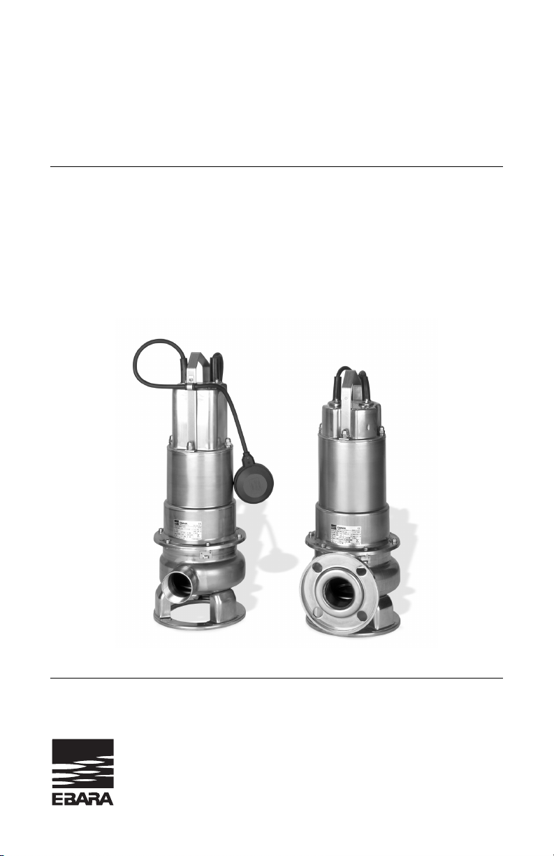
Model DWU, DWXU
Dominator
TM
EBARA Fluid Handling
EBARA International Corporation
Operating Instructions, Installation & Maintenance Manual
Submersible Sewage Pump
Page 2

Thank you for purchasing this Ebara Stainless Steel Pump. We
hope you are pleased with your purchase and that our pumps will
provide you with long service life and exceptional performance.
To ensure satisfactory service life, there are several considerations
regarding proper installation, operation and power source. Please
review the recommendations outlined within the installation and
operation manual.
Please contact your supplier (supplying dealer or contractor) if
service is necessary or if you have any questions or need further
assistance.
Please retain the following information for your records and to
help expedite service:
Purchase Date: ____________________________
Purchased From: ____________________________
____________________________
Serial No: ____________________________
(Located on the pump nameplate)
Note: For assistance locating the serial number and name plate, please
refer to page 4 of your owner’s manual.
EBARA Fluid Handling
www.pumpsebara.com
1651 Cedar Line Drive • Rock Hill, SC 29730 • (t) 803 327 5005 • (f) 803 327 5097
Page 3
EBARA Fluid Handling
www.pumpsebara.com
3
(t) 803 327-5005 • (f) 803 327-5097
DWU, DWXU
Contents
Section Page
Manufacturer Data. . . . . . . . . . . . . . . . . . . . . . . . . . . . . . . . . . . . . . . . . 3
Pump Identification Data . . . . . . . . . . . . . . . . . . . . . . . . . . . . . . . . . . . . 4
Safety Information/Warnings . . . . . . . . . . . . . . . . . . . . . . . . . . . . . . . . . 5
Electrical Information (Single phase) . . . . . . . . . . . . . . . . . . . . . . . . . . . 6
Wiring Diagrams (Single phase) . . . . . . . . . . . . . . . . . . . . . . . . . . . . . . 8
Electrical Information (Three phase) . . . . . . . . . . . . . . . . . . . . . . . . . . 10
Wiring Diagrams (Three phase) . . . . . . . . . . . . . . . . . . . . . . . . . . . . . . 11
Typical Wiring Diagram . . . . . . . . . . . . . . . . . . . . . . . . . . . . . . . . . . . . 12
Installation Instructions. . . . . . . . . . . . . . . . . . . . . . . . . . . . . . . . . . . . . 13
Installation Diagrams . . . . . . . . . . . . . . . . . . . . . . . . . . . . . . . . . . . . . . 14
Float Switch Adjustment . . . . . . . . . . . . . . . . . . . . . . . . . . . . . . . . . . . 15
Troubleshooting . . . . . . . . . . . . . . . . . . . . . . . . . . . . . . . . . . . . . . . . . . 16
Sectional Diagram . . . . . . . . . . . . . . . . . . . . . . . . . . . . . . . . . . . . . . . . 17
Assembly and Disassembly . . . . . . . . . . . . . . . . . . . . . . . . . . . . . . . . . 18
Warranty. . . . . . . . . . . . . . . . . . . . . . . . . . . . . . . . . . . . . . . . . . . . . . . . 19
Manufacturer Data
Manufacturer Data
EBARA International Corporation
1651 Cedar Line Drive
Rock Hill, SC 29730
File #: 105970
Note: All Models are CSA listed except 3HP Dominator.
Page 4
EBARA Fluid Handling
www.pumpsebara.com
4
(t) 803 327-5005 • (f) 803 327-5097
DWU, DWXU
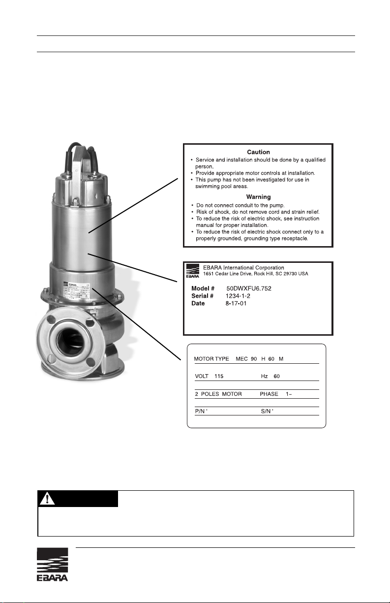
Pump Identification Data
Pump Data
Description: Submersible Sewage Pump
Model: DWU, DWXU
Year of manufacture:
see name plate on the pump (see nameplate
illustration below)
Note: This label shows all of the
electrical data required for proper
installation.
CAUTION
Call an electrician when in doubt. Improper installation can result in harm to people
and/or damage to equipment.
Page 5
EBARA Fluid Handling
www.pumpsebara.com
5
(t) 803 327-5005 • (f) 803 327-5097
DWU, DWXU
Safety Information and Introduction
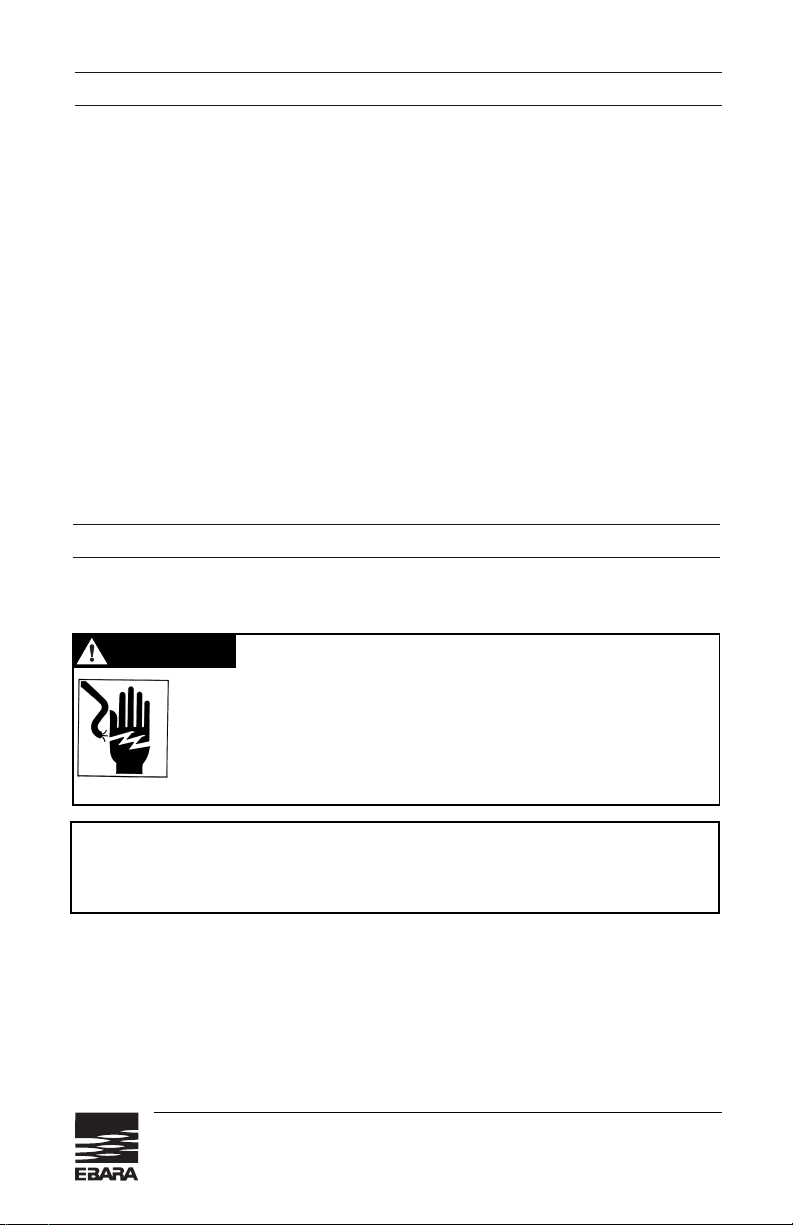
WARNING
Before handling this pump, always disconnect
the power first.
This pump should only be serviced by a qualified person or a
factory trained person.
CAUTION
This instruction manual includes necessary items for installation, operation
and
maintenance.
Read this manual carefully to ensure correct installation,
operation and maintenance.
Be sure to keep this instruction manual on hand for future reference.
EBARA’s Dominator sewage pumps are designed for reliable pumping of waste
water with suspended
solids up to 2" in diameter. Maximum fluid temperature
40°C, 104°F
(possible intermittent duty to 60°C,140°F when totally submersed).
Stainless steel construction is ideal for residential, commercial, and industrial
applications. Dual seals are a standard feature enhancing the rugged, high
service factor motor design.
The EBARA Dominator is superior in dependability and efficiency. High quality
components are stronger, dimensionally consistent, and lighter weight compared
to conventional cast iron parts.
EBARA stainless steel is engineered for the
professional and built for lasting performance and value.
Electrical Installation
Electrical service for any sump pump installation must be grounded and separately
fused or breakered directly from the entrance box with a single grounding type
receptacle. You should never touch a sump pump or discharge piping while the
pump is connected to electrical power and water is present. The pump should
be disconnected from the electrical source before handling in all cases.
Discharge Piping Installation
To assure the maximum performance from your pump, the discharge pipe size
and piping fittings should not be smaller than the discharge port of the pump.
Smaller pipe will add to friction losses and reduce the capacity of the pump.
CAUTION
Call an electrician when in doubt. Improper installation can result in harm to people
and/or damage to equipment.
Page 6
Electrical information – Single Phase
• Use a separate 15 amp circuit breaker or 15 amp fuse block with the pump.
• Do not use an extension cord with the pump.
• Do not cut off the ground pin or use an adapter fitting.
• Do not work on the pump or switch until any or all power cords are
unplugged.
• Failure to follow these guidelines my cause severe damage to the pump and
will void warranty.
IMPORTANT INSTRUCTIONS BEFORE INSTALLATION
Failure to follow these instructions may cause serious bodily injury and/or
property damage.
• Pumps are 115 V, 60Hz or 230V 60Hz.
• Please check the voltage rating on the pump nameplate prior to installation.
WARNING
Risk of electric shock
This pump is supplied with a grounding conductor or a groundingtype attachment plug. To reduce the risk of electric shock, be
certain that it is connected only to a properly grounded, groundingtype receptacle.
EBARA Fluid Handling
www.pumpsebara.com
6
(t) 803 327-5005 • (f) 803 327-5097
DWU, DWXU
Safety Information and Introduction
(continued)
Normally accepted materials are galvanized pipe, rigid plastic pipe or
acceptable
flexible pipe or hose.
Where the discharge pipe is long, a check valve is often
employed to prevent the water from flowing back into the sump when the pump
turns off. If the discharge is directed into a sanitary sewer, a suitable anti-siphon
device or a free flow check valve should be inserted in the line to prevent backflow into the pit.
Pump Installation
When the sump, electrical and discharge plumbing installation is complete and
ready for the pump, clean all solid debris from the pit. Complete the plumbing
connection to the pump and then plug the pump into the electrical outlet. A few
extra minutes to test the sump pump installation are now in order.
Fill the sump with water, note the turn on and turn off level of the pump, and the
pumping cycle. This will allow you to calculate the approximate discharge flow of
the pump system. If everything is operating properly, install the sump cover.
Page 7

EBARA Fluid Handling
www.pumpsebara.com
7
(t) 803 327-5005 • (f) 803 327-5097
DWU, DWXU
Electrical information – Single Phase
(continued)
1. Before installing or servicing your pump, BE CERTAIN pump power source is
disconnected.
2. Installation and electrical wiring must adhere to state and local codes. Check
appropriate community agencies, or contact local electrical and pump
professionals.
3. CALL AN ELECTRICIAN WHEN IN DOUBT. Pump should be connected to
a separate 15 amp circuit breaker or 15 amp fuse block. Plugging into existing
outlets may cause low voltage at motor, causing blown fuses, tripping of
motor overload, or burned out motor.
4. Do not connect pump to a power supply until permanently grounded. For
maximum safety, ground pump to a circuit equipped with a ground fault
interrupter device.
5. Voltage of power supply must match the voltage of the pump.
6. Before installing pump, clear sump basin of any water, debris, or sediment.
WARNING!
Sump basin must be vented in accordance with local plumbing codes.
EBARA DOMINATORS are not designed for and CANNOT be installed in
locations classified as hazardous in the National Electric Code,
ANSI/NFPA 70.
Page 8

EBARA Fluid Handling
www.pumpsebara.com
8
(t) 803 327-5005 • (f) 803 327-5097
DWU, DWXU
Wiring Diagram for Automatic Pumps (Single Phase)
• Output 1/2 to 1 HP (0.4kw to 0.75kw)
115V
230V
• Output 1
1
/2HP (1.1kw)
230V
Page 9

EBARA Fluid Handling
www.pumpsebara.com
9
(t) 803 327-5005 • (f) 803 327-5097
DWU, DWXU
Wiring Diagram for Manual Pumps (Single Phase)
• Output 1/2 to 1 HP (0.4kw to 0.75kw)
115V
• Output
1
/2 to 1 HP (0.4kw to 0.75kw)
230V
• Output 2HP (1.5kw)
230V
• Output 11/2HP (1.1kw)
230V
Page 10

EBARA Fluid Handling
www.pumpsebara.com
10
(t) 803 327-5005 • (f) 803 327-5097
DWU, DWXU
Electrical Information – Three Phase
WARNING
Check that the power is locked off and disconnected before working
on pump. All electric work should be performed by a qualified electrician and all national and local electrical codes must be observed.
(2) Cable
a) Never let the end of the cable contact water.
b) If the cable is extended, do not immerse the splice in water.
c) Fasten the cable to the discharge piping with tape or vinyl strips.
d) Install the cable so that it will not overheat. Overheating is caused by coiling
the cable and exposing it to direct sunlight.
(3) Grounding
As shown in Fig. 5 ground the green/yellow wire (label E). Under no
circumstances should the green/yellow wire be connected to the power supply.
(4) Use short circuit breakers to prevent danger of electrical shock.
NOTE:
Use with approved motor control that matches motor input in full load amperes.
Utiliser un démarreur approuvéconvenant au courant ápleine charge du moteur.
Figure 4
MOTOR WIRING DIAGRAM
U phase: black
V phase: red
W phase: white
E phase: green/yellow
ground
plate
Power Lead
Protector Cable*
*Protection Cable must be
connected or warranty will be void.
(1) Wiring
a) Wire as indicated in Fig. 4
b) Loose connections will stop the pump. Make sure all electrical connections
are secure.
Page 11

EBARA Fluid Handling
www.pumpsebara.com
11
(t) 803 327-5005 • (f) 803 327-5097
DWU, DWXU
Wiring Diagram for Manual Pumps (Three Phase)
230V
460V
Page 12

EBARA Fluid Handling
www.pumpsebara.com
12
(t) 803 327-5005 • (f) 803 327-5097
DWU, DWXU
Wiring Diagram
Typical Wiring Diagram
1. Run
2. Stop
3. Brown
4. Blue
5. Black
6. Red
7. Yellow/Green
8. White
SPECIAL NOTICE
for Cord Connected Pumps
Ebara Dominator pumps are not designed for and CANNOT be installed in any
location classified as
hazardous
by the National Electric Code ANSI/NFPA 70.
• Connection devices shall provide for a watertight connection to the power
supply and provide adequate strain relief for the cord.
• Installation of the box shall be a Listed watertight connection box used with
a Listed, liquid-tight fitting suitable for the cord.
• Connection boxes should be sized in accordance with National Electric
Code specifications and installed as intended for the application.
• All connection devices are to be provided by the installer.
• Only qualified personnel shall service and install the pump.
Page 13

Pump Installation
1. Clean the installation area.
2. Under no circumstances should the cable be pulled while the pump is being
transported or installed. Attach a chain or rope to the grip and install the
pump.
3. This pump is NOT to be installed on its side. Ensure that it is installed upright
and on a secure base.
4. Install the pump at a location in the tank where there is the least turbulence.
5. If there is a flow of liquid inside the tank, support the cable where appropriate.
6. Install piping so that air will not be entrapped. If piping must be installed in
such a way that air pockets are unavoidable, install an air release valve
wherever such air pockets are most likely to develop.
7. Do not permit end of discharge piping to be submerged as backflow will
result when the pump is shut down.
8. Non-automatic pumps do not have an automatic operation system based on
built-in floats. Do not operate the pump for an extended period of time with
the water level near the minimum operation level as the automatic cut-off
switch is incorporated inside the motor will be activated.
EBARA Fluid Handling
www.pumpsebara.com
13
(t) 803 327-5005 • (f) 803 327-5097
DWU, DWXU
Installation Instructions
WARNING
When lifting the pump, attach an appropriate lifting cable or rope
to the lifting handle before installation.
Do not lift the pump by the electrical cables.
Handle the cables very carefully. Excessive bending or pulling
may damage the cable and molded seal, resulting in insulation
failure. Protect cable ends against water intrusion.
CAUTION
Check rotation BEFORE installation. Correct rotation is clockwise when viewed from
top of the motor. Read ELECTRICAL WIRING.
Page 14

EBARA Fluid Handling
www.pumpsebara.com
14
(t) 803 327-5005 • (f) 803 327-5097
DWU, DWXU
Typical Installation with Quick Disconnect
Typical Installation with Pipe
Page 15

EBARA Fluid Handling
www.pumpsebara.com
15
(t) 803 327-5005 • (f) 803 327-5097
DWU, DWXU
Float Switch Adjustment
Float Switch Adjustment
Float switch should be adjusted to ensure unrestricted operation.
• Loosen float adjustment screw.
• Adjust float length by sliding float cord through bracket.
• Minimum cord length from bracket “A” to float “B” shall be 6''.
• Tighten adjustment screw after adjustment.
A
Float adjustment screw
B
Page 16

EBARA Fluid Handling
www.pumpsebara.com
16
(t) 803 327-5005 • (f) 803 327-5097
DWU, DWXU
Troubleshooting Checklist
POSSIBLE CAUSES
• Line circuit breaker is off, or fuse is blown or loose.
• Water level in sump has not reached turn-on level as indicated in
installation drawing.
• Pump cord is not making contact in receptacle.
• Float is stuck. It should operate freely in basin.
• If all of the above are OK, consult your distributor.
• Check valve is installed backwards. Arrow on valve should point in
direction of flow.
• Discharge shut-off valve (if used) may be closed.
• Pump is air-locked. Start and stop several times by plugging and
unplugging cord. Check for clogged vent hole in pump case.
• Impeller or volute openings are fully or partially clogged. Remove
pump and clean.
• Vertical pumping distance is too high. Reduce distance or resize pump.
• Float is stuck in up position. Be sure float operates freely in basin.
• Defective float switch.
• Pump is air-locked. Start and stop several times by plugging and
unplugging cord.
Check for clogged vent hole in pump case.
• Vertical pumping distance is too high. Reduce distance or resize pump.
• Impeller or volute openings is fully or partially clogged. Remove
pump and clean.
• Pump impeller is partially clogged causing motor to run slow and
overload. Remove pump and clean.
• Motor stator may be defective.
• Fuse size or circuit breaker may be too small. Must be 15 amps.
• Volute opening is fully or partially clogged. Remove pump and
clean.
• Pump impeller is partially clogged causing motor to run slow and
overload. Remove pump and clean.
• Motor stator may be defective.
• Volute opening is fully or partially clogged. Remove pump and clean.
PROBLEM
Pump does not run or
hums.
Pump runs but does not
deliver water.
Pump runs and pumps out
sump, but does not stop.
Pump runs but delivers
only a small
amount of water.
Fuse blows or circuit
breaker trips when
pump starts.
Motor runs for a short
time, then stops.
Page 17

EBARA Fluid Handling
www.pumpsebara.com
17
(t) 803 327-5005 • (f) 803 327-5097
DWU, DWXU
Sectional View
Contact your supplier for spare parts availability.
001
016-1
016-2
016-3
021
039
095
107
111
115-1
115-2
115-3
117
125
129
135-1
135-2
135-3
Casing
Casing Cover
Disk
Seal Support
Impeller
Key
Float Switch Stay
Casing Ring
Mechanical Seal
O-ring
O-ring
O-ring
Gasket
Impeller Bolt
Nut
Washer
Washer
Washer
304 SS
304 SS
304 SS
304 SS
304 SS
304 SS
—
Viton
—
Viton
Viton
Viton
Viton
304 SS
304 SS
304 SS
304 SS
304 SS
AISI 304
AISI 304
AISI 304
AISI 304
AISI 304
AISI 304
AISI 304
AISI 304
AISI 304
AISI 304
AISI 304
1
1
1
1
1
1
1
1
1 Set
1
1
3
1
1
4
1
1
4
Part
No.
Part Name Material
ASTM, AISI
Code
No. for
1 Unit
200
262
801
802
†
809
811
814
816
817
830
844
848
849-1
849-2
862-1
862-2
915
932
Lifting Hanger
Float Switch
Rotor
Stator
Capacitor
Submersible Cable
Motor Frame
Bracket
Bracket
Shaft
Motor Protector Bracket
Motor Protector
Ball Bearing
Ball Bearing
Cable Connector
Cable Connector
External Terminal
Capacitor Holder
304 SS
—
—
—
—
—
304 SS
304 SS
304 SS
304 SS
Plastic
—
—
—
Rubber (NBR)
Rubber (NBR)
—
Nylon
AISI 304
AISI 304
AISI 304
AISI 304
AISI 304
1
1
1
1
1
1
1
1
1
1
1
1
1
1
1
1
1
Part
No.
Part Name Material
ASTM, AISI
Code
No. for
1 Unit
DW(F)U, DW(F)AU Single Phase Motor
Three Phase Motor
DWX(F)U, DWX(F)AU
Page 18

EBARA Fluid Handling
www.pumpsebara.com
18
(t) 803 327-5005 • (f) 803 327-5097
DWU, DWXU
Disassembly and Assembly
1. Disassembly
When disassembling pump, have a piece of cardboard or wooden board ready
to place the different parts on as you work. Do not pile parts on top of each
other. They should be laid out neatly in rows. The O-ring and gasket cannot be
used again once they are removed. Have replacement parts ready.
Disassemble in the following order, referring to the sectional view.
Be sure to cut off power source before beginning disassembly.
(1)Loosen casing bolts and remove casing.
(2)Loosen bolt at end of pump shaft and lift impeller off shaft.
(3)Remove pump shaft key and mechanical seal.
(4)Loosen inner casing bolts and remove inner casing.
Note 1:
Contaminated oil should be replaced. Drain the lubricant oil into a
container.
(5)Remove the mechanical seal from the main shaft.
Note 2:
Be careful not to cut your fingers on the shaft key groove when
pulling out the mechanical seal.
Note 3:
Be careful not to scratch or bend the pump shaft during disassembly.
2. Assembly
Re-assemble in reverse order of disassembly.
Be careful of the following points.
(1) During re-assembly, rotate the impeller by hand and check for smooth
rotation.
(2) Replace the O-ring.
(3) Fill oil chamber with clean mineral oil.
(4) Replace all parts that are damaged.
(5) Tighten bolts evenly.
Please obtain O-rings, and other parts from pump dealer.
* All specifications subject to change without notice.
In this catalog, the particulars in { } are in accordance with the International
System of Units (SI) and given for reference only.
Page 19

EBARA Fluid Handling
www.pumpsebara.com
19
(t) 803 327-5005 • (f) 803 327-5097
DWU, DWXU
Warranty
COMMERCIAL PUMP/ PRODUCTS LIMITED WARRANTY
Ebara International Corporation, Rock Hill, SC (“EIC-RH”) warrants to the original purchaser
only (“Customer”) that the EIC-RH Commercial Pump/Product (“Pump”) will be free of
defects in workmanship and material for a period of twelve (12) months from the date of
installation or eighteen (18) months from the date of shipment by EIC-RH, whichever
comes first, provided that notification of any such defect is promptly given in writing to
EIC-RH. Customer may be required at EIC-RH’s request to verify that it is the
Customer of the Pump and that the Pump was installed and operated in accordance
with EIC-RH’s instructions.
EIC-RH’s sole obligation under this warranty will be to repair or replace with a new or
reconditioned Pump, such Pump as has failed or has been found to be defective during
the warranty period, or at EIC-RH’s sole option, to refund to the customer an equitable
part of the purchase price. In no event shall EIC-RH’s cost responsibility exceed the initial
purchase price paid by the Customer for the Pump.
EIC-RH shall be liable only for the cost of the Pump, or the cost of repair or replacement
of any defective Pump. Customer shall be responsible for labor, cost of removal and
installation at Customer’s premises, transportation and insurance costs to EIC-RH and
any other incidental costs.
This warranty is void and does not apply if damage is caused by improper installation,
improper maintenance, accident, alteration, abuse, misuse or if the Pump has been
disassembled prior to warranty evaluation without written authorization from EIC-RH.
Warranty service and information for return procedures will be provided by EIC-RH
upon receipt of written notice describing the defect or problem to:
Ebara International Corporation
Warranty/Claims
1651 Cedar Line Drive
Rock Hill, SC 29730
803-327-5005 (Phone) • 803-327-5097 (Fax)
THE FOREGOING WARRANTY IS THE SOLE AND EXCLUSIVE WARRANTY ON
THIS PUMP, AND ALL OTHER WARRANTIES, EXPRESSED OR IMPLIED, INCLUDING
ANY WARRANTY OF MERCHANTABILITY OR FITNESS FOR A PARTICULAR PURPOSE, ARE DISCLAIMED AND EXCLUDED FROM THE TERMS OF THIS WARRANTY.
EIC-RH'S SOLE OBLIGATION IN CASE OF ANY DEFECT WILL BE TO PROVIDE THE
WARRANTY SERVICE SPECIFIED ABOVE. THE FOREGOING IS CUSTOMER'S
SOLE AND EXCLUSIVE REMEDY, WHETHER IN CONTRACT, TORT OR OTHERWISE
AND EIC-RH SHALL NOT BE LIABLE FOR ANY CONSEQUENTIAL OR INCIDENTAL
DAMAGES OF ANY KIND WHATSOEVER.
Page 20

EBARA Fluid Handling
1651 Cedar Line Drive • Rock Hill, SC 29730
(t) 803 327 5005 • (f) 803 327 5097
www.pumpsebara.com
© 2005 EBARA International Corporation EIC DWU1002 0609
Contact your dealer or supplier
for more information about other Ebara products:
 Loading...