

EBAA Iron 2008PTC Installation Manual
Series 2008PTC
Restraint and Accessories for IPS O.D. PVC Pipe at
Mechanical Joint Fittings
Installation Instructions
1. Identify the pipe. The 2000PV is for use with PVC and HDPE pipe. The 4-inch through 12-inch size may
be used on C900 or IPS PVC pipe as well as C906 HDPE pipe. Check to see if the spacers under the screws
are in place. If the pipe is C900 or is ductile iron O.D., proceed with spacers in place. If the pipe is IPS O.D.,
remove the spacers. Since 3-inch, 14-inch and greater size restraints are only used with one pipe diameter
(C900), no spacers are used. If used on C906 HDPE pipe, a internal pipe wall stiener must be used.
2. Clean the socket and the plain end. Lubrication and additional cleaning should be provided by brushing both
the gasket and the plain end with soapy water or an approved pipe lubrication meeting the requirement of
ANSI/AWWA C111/A21.11 just prior to slipping the gasket onto the plain end for joint assembly. Place the
gland on the plain end with lip extension toward the plain end, followed by the gasket with the narrow edge
of the gasket toward the plain end. [The gasket provided may be the EBAA-SEAL® Improved Mechanical
Joint Gasket, there is no narrow end as the gasket is bi-directional. In certain sizes, use of the EBAA-SEAL is
required to achieve the pressure ratings of the MEGALUG.]
CONTENTS
NOTE: In cold weather it is preferable to warm the gasket to facilitate assembly of the joint.
3. Insert the pipe into the socket and press the gasket rmly and evenly into the gasket recess. Keep the joint
straight during assembly.
4. Push the gland toward the socket and center it around the pipe with the gland lip against the gasket. Insert
bolts and hand tighten nuts. Make deection after joint assembly but before tightening bolts.
5. Tighten the bolts to the normal range of torque as indicated [3-inch 45-60 ft.-lbs., 4 through 24-inch 75-90 ftlbs., 30 and 36-inch 100-120 ft.-lbs., and 42, 48 and 54-inch 120-150 ft.-lbs.] While at all times maintaining
approximately the same distance between the gland and the face of the ange at all points around the socket.
This can be accomplished by partially tightening the bottom bolt rst, then top bolt, next the bolts at either
side, nally the remaining bolts. Repeat the process until all bolts are within the appropriate range of torque.
6. Tighten the torque limiting twist-o nuts in a clockwise direction (direction indicated by arrow on top of nut)
until all wedges are in rm contact with the pipe surface. Continue tightening in an alternating manner until
all of the nuts have been twisted o.
7. If removal is necessary, utilize the ⅝ inch hex heads provided. If reassembly is required, assemble the joint
in the same manner as above; tighten the screws to 60 to 80 ft-lbs. If the Series 2000PV restraint is removed
from the pipe, be sure that all of the screws, spacers (if required), and wedges are in place before the restraint
is reassembled.
Steps 2-5 are requirements of AWWA Standard C600-17
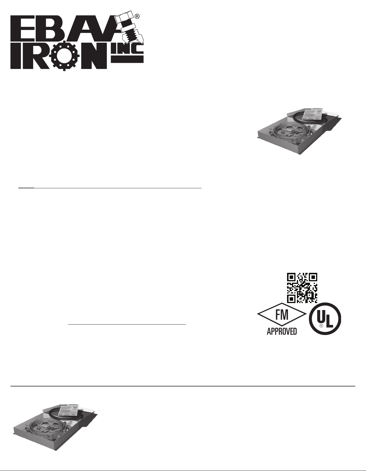
Qty. Description
®
1 8 in. 2000PV MEGALUG
Restraint
1 8 in. Transition Gasket
6 ¾ in. by 4 in. T-Bolts w/ Nuts
1 Gasket Lubrication Packet
Restraints Made in The USA
For use on water or wastewater pipelines subject
to hydrostatic pressure and tested in accordance
with either AWWA C600 or ASTM D2774
0419-AA
APPROXIMATE SHIPPING WEIGHT: 18 lbs.
Copyright 2019 © EBAA IRON, Inc. All Rights Reserved
Series 2008PTC
Restraint and Accessories for IPS O.D. PVC Pipe at
Mechanical Joint Fittings
2008PTC
EBAA IRON SALES, Inc.
P.O. Box 857, Eastland, TX 76448
Tel: (254) 629-1731
Fax: (254) 629-8931
Toll: (800) 433-1716
contact@ebaa.com
www.ebaa.com
Made in the USA
 Loading...