

KF700 SERIES
OWNER’S MANUAL
KF750 | KF755 | SB750


i
KF700 Series Owner’s Manual
TABLE OF CONTENTS
Section 1 Read This First.................................................................................................................................................ii
1.1 Safety Precautions ..............................................................................................................................ii
1.2 General Precautions...........................................................................................................................ii
1.3 Important Information for Professional Riggers ......................................................................ii
Section 2 Unpacking .......................................................................................................................................................iii
2.1 Shipping Damage..............................................................................................................................iii
2.2 Returning Products to EAW ............................................................................................................iii
Section 3 Quick Start .......................................................................................................................................................iv
3.1 Important Safety and Rigging Information ..............................................................................iv
3.2 Audio Signal Connections ..............................................................................................................iv
Section 4 Description ......................................................................................................................................................1
4.1 Overview................................................................................................................................................1
Section 5 Operation..........................................................................................................................................................2
5.1 KF700 Series Products.......................................................................................................................2
5.2 Input Connections..............................................................................................................................3
5.3 Mechanical Characteristics and Accessories .............................................................................3
5.4 Electrical Characteristics and Accessories..................................................................................5
5.5 Array Design .........................................................................................................................................6
5.6 System Truck-Pack..............................................................................................................................7
Section 6 Maintenance and Service ......................................................................................................................8
6.1 Warranty ................................................................................................................................................8
6.2 How to Contact EAW..........................................................................................................................8
6.3 System Maintenance and Repair Tips..........................................................................................9
6.3.1 KF750F..................................................................................................................................9
6.3.2 KF750P...............................................................................................................................12
6.3.3 KF750P-WP.......................................................................................................................14
6.3.4 KF755F...............................................................................................................................16
6.3.5 KF755P...............................................................................................................................19
6.3.6 KF755P-WP.......................................................................................................................21
6.3.7 SB750F...............................................................................................................................22
6.3.8 SB750P...............................................................................................................................23
6.3.9 SB750P-WP.......................................................................................................................24
Section 7 Specifications ..............................................................................................................................................25
Congratulations on purchasing the latest sound reinforcement innovation from Eastern Acoustic Works. The KF700
Series is built upon the same fundamental design principles that EAW has upheld since the introduction of the
KF850 Series of loudspeakers in the 1980’s. This new product line draws elements from Virtual Array Technology™
and PhasedPoint Source Technology™, combining these with new patented advances in transducer design and system
integration. The KF700 Series centers on a design approach that optimizes building arrays in the three dimensions of
physical space while also addressing the key acoustical issues that reside in the fourth dimension of time.

ii
Section 1 Read this first
The terms “Caution,” “Warning” and “Danger” are used throughout this manual to alert
the reader to important safety considerations. If you have any questions about any
aspects of these cautions, contact your local dealer, distributor or EAW.
CAUTION: describes an operating condition or user action that may expose the equipment
or user to potential damage or danger.
WARNING: describes an operating condition or user action that will cause damage to the
equipment or injure the user.
DANGER: describes an operating condition or user action that will immediately damage
the equipment or be extremely dangerous or possibly life-threatening to the user.
1.1 Safety Precautions
Rigging (flying) must be performed only by a professional rigger. See Section 1.3 for
information for professional riggers.
1.2 General Precautions
WARNING: Some aspects of rigging and other related fields for which EAW manufactures,
sells or distributes equipment are potentially hazardous. Any person using this equipment
is personally responsible for his own safety. EAW transactions are made with the assumption
that the purchaser is a qualified individual or will have only qualified individuals perform
work with the equipment. EAW will not be liable for any damages arising from the use of
equipment sold to purchaser.
1.3 Important Information about Rigging
Prior to suspending any EAW loudspeaker enclosures overhead, it is essential that the
user
be familiar with the load ratings, rigging techniques and special safety considera
tions
appropriate to suspending loudspeakers overhead. The user must determine the load
requirements, dynamic loading and any other contributing factors affecting the flown
loudspeakers. The user must determine the proper safety factor for specific applications
and the required load rating of the connection points. EAW strongly recommends that all
rigging be done in accordance with and in compliance with all federal, state and local
regulations, relative to properly securing suspended loads prior to usage. The user
assumes liability for proper design, installation and use of rigging systems.
EAW strongly recommends the following rigging system practices:
1.
Documentation: Thoroughly document the rigging design with detailed drawings
and parts lists.
2.
Analysis: Have a licensed structural engineer, registered architect or other qualified
professional review and approve the rigging design before its implementation.
3. Installation: Have a qualified professional rigger install and inspect the rigging
system.

iii
DANGER: Loudspeakers should be suspended overhead only by persons with a knowledge of the proper hardware and rigging techniques. When stacking or pole-mounting
loudspeakers, be sure they are stabilized and secured from falling over or being accidentally
pushed over. Failure to follow these precautions may result in damage to the equipment,
personal injury, or death.
EAW strongly recommends the following rigging system practices:
1. DOCUMENTATION:
Thoroughly document the rigging system design with
drawings and detailed parts lists.
2. PROFESSIONAL REVIEW:
Have a licensed structural engineer, registered
architect or other qualified professional review and officially approve the
rigging design before its implementation.
3. PROFESSIONAL INSTALLATION:
Have the rigging system installed and
inspected by a qualified professional rigger.
Section 2 Unpacking
2.1 Shipping Damage
You should have already visually inspected the outside of the shipping carton and noted
any damage on the shipping bill you signed. After unpacking, if you find concealed damage
to the loudspeaker, save the packing materials for the carrier’s inspection, notify the carrier
immediately and file a shipping damage claim.
Although EAW will help in any way possible,
it is always the responsibility of the receiving
party to file any shipping damage claim.
The carrier will help prepare and file this claim.
2.2 Returning Products to EAW
If this loudspeaker must be returned to EAW, contact EAW for a Return Authorization. Use
the original shipping carton and packing materials. If the shipping carton is damaged,
contact EAW for a new carton. EAW will not be responsible for damage caused by
inadequate packing.

iv
Section 3 Quick Start
NOTE: This section is intended only for qualified professional installers.
3.1 Important Safety and Rigging Information
CAUTION: Read all of Section 1, "Read This First", for important general, safety and
rigging precautions.
3.2 Audio Signal Connections
The audio signal connections are via Neutrik NL8 connectors or barrier strips. The two
NL8s are wired in parallel.
KF750F - 2 x NL8
LF1: pins 1 (+/-)
LF2: pins 2 (+/-)
MF: pins 3 (+/-)
HF: pins 4 (+/-)
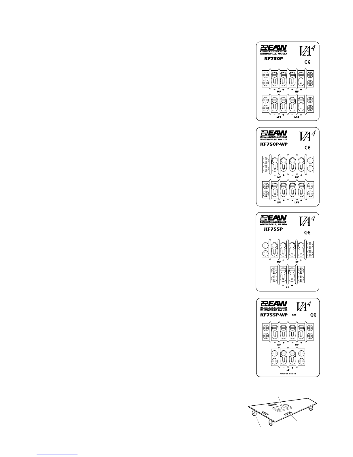
KF750P and KF750P-WP - 2 x 4-terminal Barrier Strips
LF1: bottom strip terminals 1 (-) and 2 (+)
LF2: bottom strip terminals 3 (-) and 4 (+)
MF: top strip terminals 1 (-) and 2 (+)
HF: top strip terminals 3 (-) and 4 (+)
KF755F - 2 x NL8
Pins 1 (+/-) not used
LF: pins 2 (+/-)
MF: pins 3 (+/-)
HF: pins 4 (+/-)
KF755P and KF755P-WP - 1 x 2-terminal + 1 x 4-terminal Barrier Strips:
LF: bottom strip terminals 1 (-) and 2 (+)
MF: top strip terminals 1 (-) and 2 (+)
HF top strip terminals 3 (-) and 4 (+)
SB750 - 2 x NL8
Left driver*: pins 1 (+/1)
Right driver*: pins 2 (+/-)
Not used: pins 3 (+/-)
Not used: pins 4 (+/-)
*Note: Driver position is looking from front.

1
Section 4 Description
4.1 Overview
Professional loudspeaker systems are designed to optimize spectral, spatial, temporal and
usability performance attributes. Quite often optimization in one area compromises
performance in another. Thus, loudspeaker design is the art of balancing these goals while
minimizing compromise. In order to achieve these goals for the KF700 Series, key developments allowed for performance enhancement in each area without compromise in others.
4.1.1 SPECTRAL
The KF700 Series are true three-way designs. The goal was to develop
systems with greater
low frequency extension and greater overall mid frequency bandwidth. Traditionally these
goals required increased physical size. This was not an option. The
KF700 Series loudspeak-
ers were designed as uni-axial enclosures in which all the transducers
(woofer, mid-range,
and high frequency) share a common acoustic axis. This
permitted using larger horns for a
more consistent coverage pattern over a wider frequency
range and provided more available
enclosure volume for deeper bass response while
actually reducing physical size. A new,
patented mid frequency phase plug was also
developed that allows for improved upper
mid frequency response from a cone transducer
through a large format horn.
4.1.2 SPATIAL
The KF700 Series have 35° x 35° coverage patterns. This enhances building arrays and
increases overall system output capability. Conventional phase plugs create beam-width
narrowing in the upper portion of the mid-range. The patented KF700 Series mid
frequency phase plug provides upper mid-range extension without creating this narrowing.
The uni-axial approach minimizes the impact of “apparent apex error”. This occurs when
the separation between physically misaligned transducers changes as the listening point
changes. The KF750 horn designs draw heavily from the SimplePhase™ horns used in the
KF900 Series in order to achieve more seamless coverage between arrayed enclosures.
The low frequency section uses multiple woofers in a dipole configuration to reduce off
axis low frequency energy and thus increase directivity. Research showed that the directivity
of the low frequency section could be smoothly matched to that of the mid frequency section.
This is done by optimizing the ratio between the woofer spacing within the mid frequency
horn and the dimensions of the mid frequency horn mouth. This configuration with its
dimensional ratio is patented.
4.1.3 TEMPORAL
The temporal focus is once again on the mid-range section. A mid frequency cone transducer tends to provide better tonality and lower distortion than standard compression
drivers, but can smear events in the time domain. This was resolved through a redesign of
the mid-range transducer geometry. The multi-axis approach and its subsequent impact
on apparent apex error also serves to minimize temporal inconsistencies from transducer
to transducer within the enclosure.
4.1.4 USABILITY
Usability goals were satisfied by making the enclosures small. The uni-axial approach
met all the performance goals while allowing for a reduction in overall package size. For
the most consistent coverage pattern through the low to mid frequency crossover region,
the optimal spacing of woofers is smaller than the optimal height of the mid frequency
horn. This allows the woofers to reside within the mid frequency horn, once again
resulting in a small overall package size.
In order to provide simple rigging, the standard KF850 flytrack was chosen. The KF750
utilizes these tracks on the front and back of the enclosure, eliminating the need for putting
fingers between cabinets during array assembly or disassembly. Finally, some internal
parts have been molded of lightweight materials in order to meet the desired enclosure
weight of less than 200 pounds.
4.1.5 VA4DEFINED
The system overview illustrates that the KF700 Series development was driven by enhancing
the acoustical performance of the loudspeaker systems as it relates to its arrayability. Each
loudspeaker must therefore array effectively both horizontally and vertically. Consistent
controlled coverage patterns in three dimensions guarantees predictable array results
from venue to venue.
The development goals also dictated that the KF700 Series improve upon the time
domain behavior, particularly in the vocal region. The ability of a loudspeaker to main
tain
the temporal integrity of the original input signal is easily as important as the frequency
response in determining the quality of the sound reproduction. Therefore, if harmonics
lead or lag fundamentals in the reproduction, then the original signal, and perhaps even
the intent of the performer, will be distorted. The ability to maintain the input signal’s
temporal integrity while delivering smooth frequency response to a well-defined coverage
area is ultimately the goal of any loudspeaker.
Consistently achieving the desired coverage from a loudspeaker array for a given venue
is governed by performance in the three dimensions of space. Maintaining temporal
coherence is governed by the fourth dimension of time. Meeting all of these criteria truly
addresses system performance in four dimensions. This four-dimensional design
approach is VA
4
technology.
4.1.6
WEATHER-PROTECTED (WP MODELS)
The KF700P-WP and SB750P-WP models are weather-protected for permanent
install
ations. The exterior of the enclosure is laminated with a water-resistant fiberglass
coating. A 2-layer grille is used to prevent water from entering the front of the enclosure.
The outside layer is powder-coated perforated steel for physical protection. The rear layer
is a 1/8 inch thick foam to break up driven water droplets. Behind the grille assembly, a
layer of 100 x 100 wires per inch stainless steel mesh is affixed to the enclosure to prevent
any water spray from entering the front of the enclosure. The input panel and back
doghouse are weather-sealed with rubber strips to prevent water intrusion.
Section 5 Operation
5.1 KF700 Series Products
5.1.1 KF700 MODELS
Model Name Description Primary Application
KF750F Three-way Concert touring
KF750P Three-way Permanent installation
KF750P-WP Three-way Outdoor installation
KF755F Three-way Concert touring downfill
KF755P Three-way Permanent installation downfill
KF755P-WP Three-way Outdoor installation downfill
SB750F Dual 18-in. Concert touring subwoofer
5.1.2 KF700 SERIES PRODUCT WEIGHTS
System Net (lb / kg) Shipping (lb / kg)
KF750F 198 / 90.0 230 / 104.6
KF750P 187 / 85.0 201 / 91.4
KF750P-WP 205 / 93.2 221 / 100.5
KF755F 198 / 90.0 232 / 105.5
KF755P 180 / 81.8 203 / 92.3
KF755P-WP 205 / 93.2 223 / 101.4
SB750F 193 / 87.7 202 / 91.8
KF750
KF755
2
3
5.1.3
EQUIPMENT SUPPLIED
Each model is shipped individually boxed, two of which fit on one shipping pallet.
Concert touring versions include four cable links, which comprise two fly clips and a
load-rated cable whose length is optimized for creating flown arrays.
5.1.4
ARRAYS
Flying one row of downfill is recommended when more than one row of KF750 loudspeakers is flown. At least one SB750F subwoofer is recommended for every two KF750s
or KF755s.
For more information on building arrays, please refer to the KF700 Touring Usage Guide
available at ftp://ftp.eaw.com/ProductGuides/KF700TouringUsageGuide.pdf. Most of
the basic array building concepts described in the Touring Usage Guide apply equally to
permanent installations.
5.2 Input ConnectIons
KF750F - 2 x NL8
LF1: pins 1 (+/-)
LF2: pins 2 (+/-)
MF: pins 3 (+/-)
HF: pins 4 (+/-)
KF750P and KF750P-WP - 2 x 4-terminal Barrier Strips
LF1: bottom strip terminals 1 (-) and 2 (+)
LF2: bottom strip terminals 3 (-) and 4 (+)
MF: top strip terminals 1 (-) and 2 (+)
HF: top strip terminals 3 (-) and 4 (+)
KF755F - 2 x NL8
Pins 1 (+/-) not used
LF: pins 2 (+/-)
MF: pins 3 (+/-)
HF: pins 4 (+/-)
KF755P and KF755P-WP - 1 x 2-terminal + 1 x 4-terminal Barrier Strips:
LF: bottom strip terminals 1 (-) and 2 (+)
MF: top strip terminals 1 (-) and 2 (+)
HF top strip terminals 3 (-) and 4 (+)
SB750 - 2 x NL8
Left driver*: pins 1 (+/1)
Right driver*: pins 2 (+/-)
Not used: pins 3 (+/-)
Not used: pins 4 (+/-)
*Note: Driver position is looking from front.
Note: All models can be special ordered with AP or EP 4, 6 and 8-conductor connectors.
5.3 Mechanical Characteristics and Accessories
5.3.1 CASTER PALL E T S
The KF700 Series includes an optional rugged caster pallet (EAW P/N 255049) designed
for years of reliable service in concert touring applications. Caster pallets can be
ordered separately in quantities suitable to particular truck packing strategies.
CENTRAL RAISED PLATFORM WITH TWO MAGNETS
THREE HANDLES
FOUR WHEEL CASTERS
4
KF700 Series caster pallets are constructed of 15 mm Baltic birch plywood with four
mounted wheel-casters. The caster pallet shares a common footprint with KF700F
enclosures. The pallet incorporates a central raised platform that keys into a recess on the
bottom of any enclosure. Magnets on the platform register to steel plates in the recess,
attaching the pallet to the enclosure. The caster pallet has three handles for easy transport
when not connected to a KF700 Series enclosure.
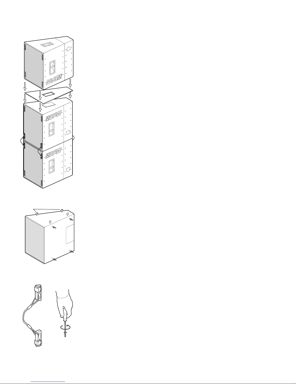
5.3.2 GROUND STACKING
All KF700(F) Series enclosures are equipped with a UHMW (Ultra High Molecular
Weight) plastic stacking pad that keys into the recess in the bottom of another enclosure
when stacked. This pad provides for a more secure stack. EAW recommends that fly hardware be used to provide additional stability. A crossed configuration of the cable links
allows for minimal slack, improving safety and stability. Stacked clusters should
also be strapped together to provide even greater stability.
In many venues, most notably theaters that do not permit flown arrays, inverted KF755s
will be used to provide upfill when stacked. This scenario forces enclosures to touch topto-top and, therefore, pad-to-pad. In order to prevent slippage and provide a more secure
stack, EAW has created a stacking plate (EAW P/N 980031)constructed of painted birch
plywood. The stacking
plate shares the KF700 Series footprint and provides a central
cutout that locks into pads on both adjoining enclosures.
5.3.3 SUSPENSION HARDWARE
WARNING: See Section 1.3 for information regarding rigging and suspending KF700
Series loudspeakers.
KF700(P and P-WP) Series installation versions utilize internal steel angles to provide a
total of sixteen (16) 3/8”-16 threaded mounting points (four each on the top, bottom
and sides). The enclosures ship with undercut 3/8-16 hardware that sits flush with the
enclosure walls. Replacement of factory-installed hardware with Grade 8 forged shoulder
eyebolts provides appropriate suspension points on an enclosure. The eyebolt manufacturer should be consulted for eyebolt working load limit specifications.
CAUTION: All four points on any given side should be utilized when hanging an
enclosure. Failure to use all four points can result in damage to the equipment, personal
injury, or death.
KF700(F) Series touring versions are equipped with two-position industry standard flytracks located in the front and rear corners. The aircraft grade aluminum track is attached
to the Baltic birch enclosure via internal angled steel that runs the full height of the enclosure. This construction is such that the enclosure bears no weight when flown. Each
KF700(F) Series touring version loudspeaker is shipped with four cable links described
above. These can be used for attaching the enclosures to fly bars as well as for attaching
vertically adjacent enclosures to each other. Enclosures should be connected using all
four available points (two front and two back) as depicted in the illustration.
Available fly bar manufacturer information can be obtained by contacting EAW.
FOUR EYE BOLTS INSTALLED INTO
TOP THREADED HANG POINTS
ARROWS INDICATE
SIDE HANG POINTS
FLY
CLIP/CABLE
INTERCONNECT
ASSEMBLIES
3/8-16 HARDWARE
WITH A 7/32 ALLEN WRENCH
REMOVING
THE
UNDERCUT

5
5.4 Electrical Characteristics and Accessories
5.4.1 INPUT SIGNALS: SYSTEM PROCESSING
While KF700 Series processing can be implemented in most commercially available
Digital Signal Processors (DSPs), EAW’s MX8600 and MC8750 DSPs are recommended.
Processor settings for specific array configurations are available in a variety of formats
that can be programmed directly into many DSPs. Formats include text lists of parameters
as well as processor-specific presets. These settings can be found on the EAW web site:
ftp://ftp.eaw.com/Processing/.
Additionally EAW offers the KF7
00 Wizard also available on the EAW web site at
ftp://ftp.eaw.com/KF700Wizard/. This program requires you to enter critical venue
dimensions and your array configuration. It will then provide you with appropriate signal
processing parameters for that venue and array configuration.
Discrete left / right KF700 arrays that do not incorporate KF755 downfills require four
distinct channels of processing per side: one for each passband of the KF750 and an
additional processing channel for SB750.
Integrating KF755 downfills into left / right arrays requires two additional channels per
side with the low frequency drivers utilizing the same processor output as the KF750
low frequency drivers.
Integrating KF755 into left / right arrays as upfills calls for two additional processing channels
per side for each row of upfill KF755s. They require only mid and high frequency
outputs because ample low frequency energy is provided by the KF750s. Each row
requires
individual delay settings to provide a coherent sum of the loudspeaker outputs in
the balcony
. Thus two rows of inverted KF755s require four processing outputs per side.
A more efficient though slightly more complex approach exists. The same upfill processing (crossovers, equalization, delay) is used for each upfill row. Thus, two processing
outputs can be used to tune the mid and high frequency sections of all the upfills. These
outputs would feed the bottom row amplifiers directly with appropriate delay set in the
processing. The ouptuts would also feed two signal delays to provide slightly more delay
for the top row of upfills. The signal delays must be carefully chosen to ensure that their
inherent propagation time plus the delay in the processor does not exceed the desired
delay for the top row of upfills.
A large KF700 Series array comprised of SB750 subwoofers, multiple rows of KF750s,
KF755 downfills, and 2 rows of KF755 upfills normally requires 8 to 10 distinct processor
outputs.
5.4.2 POWER AMPLIFIER REQUIREMENTS
All drivers (transducers) in the KF700 Series are rated based upon the results of a power
handling test procedure that is derived from the AES standard, but with a number of
important differences. Stephen Siegel, VP Engineering, outlines the specifics of the EAW
power testing procedure in the EAW Engineering Application Note ”Understanding
Loudspeaker Power Handling and Selecting the Proper Power Amplifier.” This can be
found on the EAW website.
5.4.3 DRIVER SPECIFICATIONS:
Passband Impedance Power Handling Sensitivity
SUB (each driver) 8 ohms 1000 W 98 dB
LF (each driver) 8 ohms 600 W 97 dB *
MF 8 ohms 400 W 109 dB
HF 8 ohms 200 W 116 dB
* Sensitivity for the KF750 LF section with both drivers operating is 100 dB.

6
The power handling listed for each EAW transducer is a good indicator of the size of the
amplifier that will safely drive it to full output under most conditions. Amplifier selection
is dependent upon the load presented at the amplifier output. Each doubling of loudspeaker quantity doubles the required amplifier power. In other words, two KF750s LF
drivers in parallel require an amplifier channel capable of at least 1200 W into 4 Ohms.
Driving four KF750 LF drivers in parallel (2 ohm impedance) can eliminate one amplifier
per rack. While many amplifiers are capable of driving 2 ohm impedances, low frequency
performance may be compromised. Amplifier manufacturers should be consulted to
determine the power available and distortion present when driving low impedance loads.
5.4.4 LOUDSPEAKER CABLE
The resistance of the loudspeaker cable should be as low as possible to keep cable power
losses low and to maintain an acceptable damping factor, particularly for low frequency
transducers. The loudspeaker load will significantly affect both of these factors. For a
given wire size and length of loudspeaker cable, a greater impedance load will cause a
greater power loss and lower damping factor. This fact must be considered when paralleling multiple loudspeakers on an amplifier channel.
The following are minimum recommended wire sizes for loudspeaker cabling.
(AWG = American Wire Gauge; MWG = Metric Wire Gauge):
Length of Cable Nominal Load Cable Wire Gauge
0 - 50 ft / 0 - 15 m 8 ohms 14 AWG / 16 MWG
50 - 100 ft / 15 - 30 m 8 ohms 12 AWG / 20 MWG
100 - 200 ft / 30 - 60 m 8 ohms 10 AWG / 25 MWG
Over 200 ft / 60 m 8 ohms Not recommended
0 - 50 ft / 0 - 15 m 4 ohms 12 AWG / 20 MWG
50 - 100 ft / 15 - 30 m 4 ohms 10 AWG / 25 MWG
Over 100 ft / 30 m 4 ohms Not recommended
0 - 50 ft / 0 - 15 m 2 ohms 10 AWG / 25 MWG
Over 50 ft / 15 m 2 ohms Not recommended
5.5 Array Design
5.5.1 APPROPRIATE VERTICAL CONFIGURATION
Each KF750 loudspeaker provides well-controlled 35° x 35° coverage. KF755 loudspeakers
provide the same coverage, but are vertically asymmetrical. The vertical pattern lies within
0° and -30° with maximum output at -12.5°. EASE data is available for KF700 Series
loudspeakers to aid designers in creating an appropriate vertical configuration for a fixed
installation.
KF700 (F) Series touring versions require evaluating each venue independently to determine
the most appropriate configuration for a given performance. The first step in designing an
array is designing a column that will vertically address the audience. It is easiest to determine
column requirements by examining a cross-section of the venue with appropriate stage
location and array trim height. It is easy to see that audience members seated at varying
vertical angles are seated in vastly different acoustical environments. These vertical zones
require an integrated array column targeted at seamlessly covering the entire venue from
a single location. The primary key to delivering uniform response and SPL to the entire
venue is appropriate use of different KF700 Series models to address the complex
cross-section of most venues. This topic is covered in detail in the KF700 Series Touring
Usage Guide.
11' 8"
90"
11' 8"
90"

7
5.5.2 APPROPRIATE HORIZONTAL CONFIGURATION
The horizontal coverage angle required for a venue can be readily determined through
examination of the plan view. Once the required horizontal coverage has been determined, it is easy to calculate the number of columns required to thoroughly address the
entire venue. All KF700 Series loudspeakers provide 35° of horizontal coverage. Since the
side angles of KF700 enclosures are constructed at 15° angles, horizontal coverage can be
achieved by simply tight packing as many loudspeakers or columns of loudspeakers as
are needed.The resulting 5° overlap in coverage between enclosures is intentional by
design to provide the smoothest SPL transition between enclosures.
5.6 System Truck-Pack
5.6.1 DIMENSIONAL INFORMATION
KF700 (F) Series touring versions ride on four-wheeled caster pallets with the wider set of
wheels set 23 inches apart so that ramps 30-in wide or wider are easy to negotiate. Two
individuals can quickly and easily load or unload enough loudspeakers to create even the
largest touring arrays. Two offset handles per side provide an inherent tilt when lifting to
facilitate stacking.
KF700F full-range loudspeakers are 31 inches in height. The SB750F subwoofer is 47
inches in height. KF700 Series caster pallets add 4 inches in overall height to any stacked
column. As a result, 3 high columns of KF700 enclosures or 2 high columns of SB750
enclosures can be stacked in most trucks.
CAUTION:
Ensure that you do not exceed the load weighting for the vehicle you are using.
This is especially important to consider when stacking enclosures two or more high.
DANGER: To avoid injury or death to personnel or damage to equipment, only two-high
stacks of enclosures should be rolled up or down ramps with up to a 10° slope. Do not
stack enclosures if the slope of the ramp is greater than 10°.
5.6.2 TRUCK PACKING
Smaller straight trucks typically have 90 to 95 inches of available internal width. KF700
Series enclosures can be packed into a 90-inch truck body in tightly packed rows of four.
Enclosures will stack three high on a single caster pallet. SB750 subwoofers will stack two
high in the same footprint. This configuration provides for a maximum of 48 full-range
loudspeakers within only 12 feet of truck space.
Forty-five inch road cases and decking can be used to create a base upon which two-high
stacks of full-range enclosures will fit.
European trailers can also support a 90-inch configuration. In the event that 96-inches of
internal width is available, an alternate configuration will allow for 54 full-range
enclosures in 12 feet of trailer space. This configuration calls for two alternating rows
along one wall and a single row at 90 degrees along the other wall. It should be noted that
this configuration does not leave much room for protection between rows of enclosures.
In 102-inch wide flat-floor semi-trailers with 100 inches of internal width, KF700 Series
enclosures pack five wide in alternating rows. This allows for 60 enclosures in just 12 feet
of trailer space. This configuration actually occupies 98.25 inches of actual space, so a
small amount of room remains if the trailer width varies slightly.
Regardless of trailer configuration, grilles and flytrack should be prevented from contacting
one another. Enclosures should be secured so that they do not rub up against each other
during transport. Covers or plywood sheets may be used to minimize contact during
transport. KF700 enclosures are protected with a durable finish, however, care taken during
transport will maintain them in superior condition longer .
11' 8"
96"
11' 8"
100"

8
Section 6 Maintenance and Service
6.1 Warranty
Eastern Acoustic Works, Inc. (EAW) guarantees its Loudspeaker Systems (excluding active
electronics) for a period of six years from date of original purchase against malfunction
due to defects in workmanship and materials. WP (weather-protected) product
enclosures are warranted for five years. EAW Professional Active Electronics products are
guaranteed for a period of three years from the date of original purchase against malfunction
due to defects in workmanship and materials. During the warranty period, EAW will
remedy all such defects without charge for parts or labor upon the return of the unit
together with its original sales receipt or other proof of purchase to EAW or to an
Authorized EAW Service Facility.
This warranty does not extend to damage resulting from improper installation, misuse,
neglect or abuse. Defects in, or damage to, the exterior appearance of EAW products are
specifically excluded from this warranty. In no event shall EAW be liable for incidental or
consequential damages. Repairs and/or modifications by other than EAW or its
Authorized Service Facilities automatically voids this warranty. This warranty gives you
specific legal rights and you may also have other rights which vary from state to state.
6.2 How to contact EAW
For warranty information, repair service, accessories, technical assistance, printed literature,
CD ROM information, additional performance, or other specifications, contact EAW or
visit our web site at www.eaw.com.
SERVICE LITERATURE SERVICE LITERATURE
Eastern Acoustic Works Eastern Acoustic Works
EAW Service Department EAW Literature Department
One Main Street One Main Street
Whitinsville, MA 01588 USA Whitinsville, MA 01588 USA
Tel 800-992-5013 (USA only) Tel 800-992-5013 (USA only)
Tel 508-234-6158 Tel 508-234-6158
Tel 508-234-4295 ext 133 or ext 164 Fax 508-234-8251
Fax 508-234-3776 email service@eaw.com
email service@eaw.com

9
6.3 System Maintenance and Repair Tips
OBJECTIVE:
This section illustrates the steps to follow when removing the KF700F Series loudspeaker
components. To replace the components and reassemble the loudspeaker, reverse these
instructions.
TABLE OF CONTENTS:
Section 6.3.1 KF750F .............................9
Section 6.3.2 KF750P...........................12
Section 6.3.3 KF750P-WP....................14
Section 6.3.4 KF755F ...........................16
Section 6.3.5 KF755P...........................19
Section 6.3.6 KF755P-WP ....................21
Section 6.3.7 SB750F ...........................22
Section 6.3.8 SB750P ...........................23
Section 6.3.9 SB750P-WP ....................24
CAUTION: Maintenance should only be done by an experienced technician. Improper
maintenance may cause serious injury, damage to the loudspeaker and/or void the warranty.
6.3.1 KF750F LOUDSPEAKER
PROCEDURE:
6.3.1.1 Accessing the Woofer Chamber:
Remove the grille and grille foam.
• Remove the 4 screws & washers from the center of the grille with a 5/32 allen
wrench. These attach the internal high frequency horn to the grille.
• Remove the 18 grille mounting screws and washers from the outside edge of the
grille with a 5/32 allen wrench. During removal, hold the grille and grille foam in
place. This prevents the grille foam from tearing. Do not discard the mounting
hardware.
GRILLE FOAM 712028
GRILLE 702381-0002
22X HORN & GRILLE SCREWS
1/4-20 X 1 LG BLACK 104023
& WASHERS 1/4 NYLON BLACK
105065 (ONLY 10 SHOWN)
EAW

KF750
HORN
ASSEMBLY
DISCONNECT RED LEAD +
FROM RED PUSHBUTTON
TERMINAL AND BLACK
LEAD – FROM BLACK
PUSHBUTTON TERMINAL
ON REAR OF DRIVER
10
6.3.1.2 Removing the High Frequency Horn Assembly:
This assembly is heavy. It is made up of a metal bracket, a horn and a driver with 2 elec-
trical leads. The leads must be disconnected carefully.
•
While supporting the assembly, remove the mounting screws that hold the assembly
into the cabinet with a 3/16 allen wrench. These 4 socket head screws, lock washers
and flat washers are indicated by the arrows. Do not discard the mounting hardware.
•
Disconnect the red lead + from the red pushbutton terminal and the black lead –
from the black pushbutton terminal. The terminals are on the back of the driver
.
• Lift the horn assembly away from the cabinet.
NOTE:
The high frequency diaphragm is not self aligning. Its replacement requires a
signal/tone generator for alignment. Please contact our factory for further details.
6.3.1.3 Removing the Two Woofers:
The woofer to be removed should rest in the lower half of the cabinet (as shown).
• Remove the 4 woofer mounting screws with a 3/16 allen head wrench. Do not
discard the mounting hardware.
• Lift the woofer enough to access and disconnect the two electrical leads. The top
woofer’s red pushbutton terminal has a blue lead+, and its blue pushbutton terminal has a green lead–. The bottom woofer ‘s red pushbutton terminal has a blue
lead +, and its blue pushbutton terminal has an orange lead –.
TOP 12" WOOFER 804091
DISCONNECT BLUE LEAD + FROM
RED PUSHBUTTON TERMINAL AND
GREEN LEAD – FROM BLUE
PUSHBUTTON TERMINAL
4X SCREWS 1/4-20 SOCKET HEAD
CAP 102017 USE 3/16 ALLEN
BOTTOM 12" WOOFER 804091
DISCONNECT BLUE LEAD + FROM
RED PUSHBUTTON TERMINAL AND
ORANGE LEAD – FROM
BLUE PUSHBUTTON TERMINAL

11
• Lift the woofer from the cabinet.
• Flip the cabinet and repeat the above steps for the second woofer.
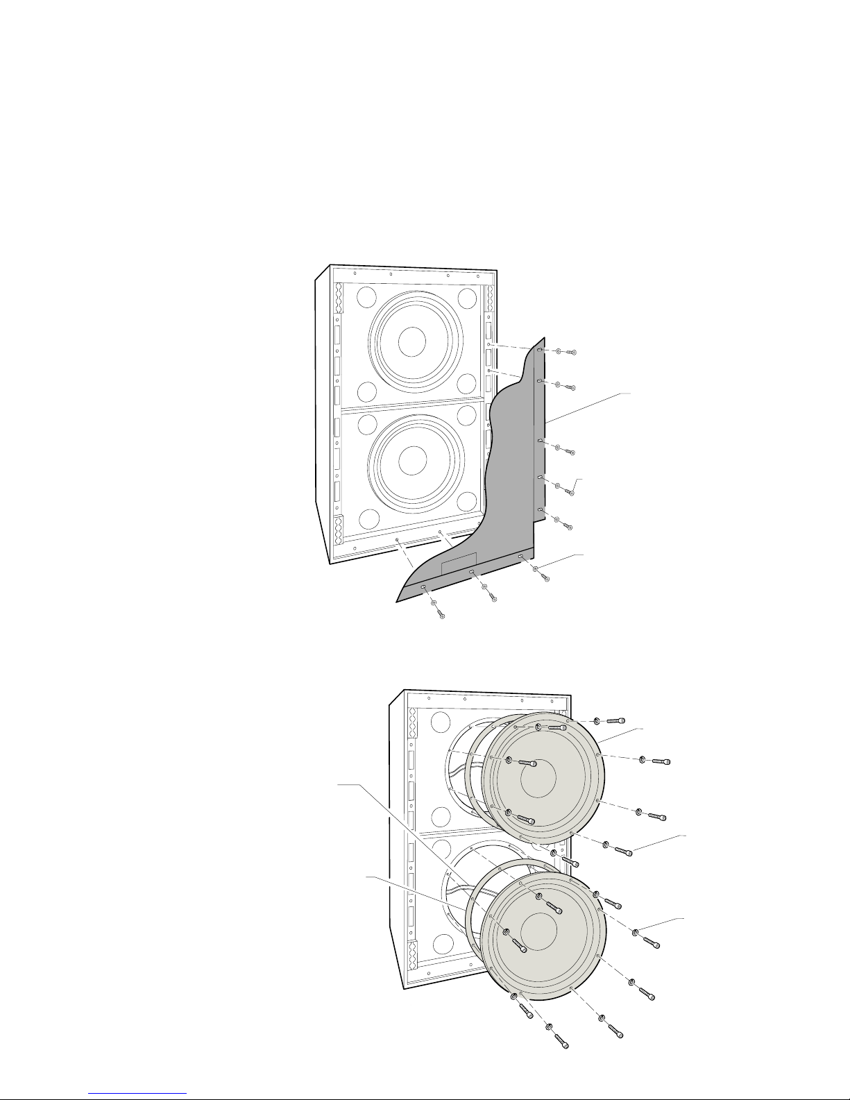
6.3.1.4 Removing the Doghouse:
To access the mid frequency driver/phase plug assembly, remove the doghouse.
• Remove the 10 phillips head screws that attach the doghouse to the loudspeaker
cabinet (5 per side, indicated by the arrows). Do not discard hardware.
After removing the 10 mounting screws, carefully move the doghouse away from the
cabinet. The internal electrical leads that connect the components are short in length
and must be handled carefully.
• Disconnect the two electrical connectors (indicated by the arrows).
• Remove the yellow lead + from the red pushbutton terminal on the phase plug
assembly.
• Remove the violet lead– from the black pushbutton terminal on the phase plug
assembly.
KF750F
DOGHOUSE
508001
4
-
4
-
3
-
2
-
KF750 PHASE PLUG ASSEMBLY 251147

4X SCREW HEX
HEAD 1/4-20 X
6-3/4 LG 102238
NOTE ORIENTATION
OF MID COVER AND
10" CONE DRIVER
10" MID PHASE PLUG 801015
& HOUSING 801019
BRACKET
4X WASHER
1/4 LOCK
105008
4X WASHER
1/4 FLAT
105007
ASSEMBLY/SFP
MID
10" CONE
DRIVER
THROAT MODE
BARRIER 801014
DISCONNECT YELLOW LEAD +
FROM RED PUSHBUTTON
TERMINAL AND BLACK LEAD –
FROM BLACK PUSHBUTTON
TERMINAL ON CONE DRIVER
KF750F CABINET WITH
DOG HOUSE REMOVED
KF750 PHASE PLUG
ASSEMBLY 251147
4X SCREW 1/4-20 X 3/4 LG
PHILIPS PAN HEAD 102039
4X WASHER
1/4 LOCK
105008
4X WASHER 1/4
FLAT 105007
12
6.3.1.5 Removing the Phase Plug Assembly:
• Remove the 4 phillips head screws, lock washers and flat washers. This assembly
is heavy and must be supported during removal. Do not discard the mounting
hardware.
6.3.1.6 Disassembling the Phase Plug Assembly :
• Remove the 4 hex head screws, lock washers and flat washers. Do not discard the
mounting hardware.
• Remove the yellow lead + from the red pushbutton terminal on the cone driver.
• Remove the black lead– from the black pushbutton terminal on the cone driver.
6.3.1.7 Reinstallation of KF750F components:
To reinstall any of the components listed in this section, reverse the appropriate disassembly procedure.
6.3.2 KF750P LOUDSPEAKER
PROCEDURE:
6.3.2.1 Accessing the Woofer Chamber:
Remove the grille and grille foam.

13
• Remove the 4 screws and washers from the center of the grille with a 5/32 allen
wrench. These attach the front of the internal high frequency horn to the grille.
• Remove the16 grille mounting screws and washers from the outside edge with
a phillips head screwdriver. During removal, hold the grille and grille foam in place.
This prevents the grille foam from tearing. Do not discard the mounting hardware.
6.3.2.2 Removing the High Frequency Horn Assembly:
Refer to Section 6.3.1.2.
6.3.2.3 Removing the Two Woofers:
Refer to Section 6.3.1.3.
6.3.2.4 Disconnecting the Doghouse:
To access the mid frequency driver/phase plug assembly, disconnect the doghouse.
• Remove the 22 phillips head screws that attach the doghouse to the cabinet. The 18
side mounting screws (9 per side, indicated by the arrows) are 5/8”long, and the 4
back mounting screws are 1-1/4”long. Do not discard the
mounting hardware.
GRILLE FOAM 712028
GRILLE 702381-0002
EAW
16X GRILLE SCREWS
#8 X 5/8"LG PHILLPS
HEAD BLACK 102102
(ONLY 7 SHOWN)
4X GRILLE WASHERS
1/4 NYLON BLACK 105065
(ONLY 2 SHOWN)
4X HORN MOUNTING
GRILLE SCREWS 1/4-20 X 1
LG BLACK 104023 USE 5/32
ALLEN HEAD WRENCH
(ONLY 2 SHOWN)
ARROWS INDICATE THE 9
DOGHOUSE MOUNTING
SCREWS 10-24 PHILLIPS
HEAD X 5/8 LG 102057
THAT MUST BE REMOVED
FROM EACH SIDE OF THE
CABINET
4X BACK DOGHOUSE
MOUNTING SCREWS
10-24 X 1-1/4 LG
PHILLIPS HEAD
102053

14
After removing the 22 mounting screws, carefully move the doghouse to access the
phase plug assembly. The internal electrical wires that connect the components are
short in length and must be handled carefully.
• Remove the yellow lead + from the red pushbutton terminal on the phase plug
assembly.
• Remove the violet lead – from the black pushbutton terminal on the phase plug
assembly
6.3.2.5 Removing the Phase Plug Assembly:
Refer to Section 6.3.1.5.
6.3.2.6 Disassembling the Phase Plug Assembly:
Refer to Section 6.3.1.6.
6.3.2.7 Reinstallation of KF750P components:
To reinstall any of the components mentioned in this section, reverse the appropriate
disassembly instructions.
6.3.3 KF750P-WP LOUDSPEAKER
PROCEDURE:
6.3.3.1 Accessing the Woofer Chamber:
Remove the grille, grille foam and wire mesh.
• Remove the 4 central screws from the grille with a 5/32 allen wrench. These attach
the front of the internal high frequency horn to the grille.
• Remove the16 grille mounting screws and washers from the outside edge with a
phillips head screwdriver. During removal, hold the grille, grille foam and wire
mesh in place. This prevents the grille foam from tearing. Do not discard the
mounting hardware.
KF750 PHASE PLUG
ASSEMBLY 251147

15
GRILLE FOAM 712028
GRILLE 702381-0002
EAW
WIRE MESH STAINLESS STEEL
16X GRILLE SCREWS #8 X 5/8"LG
PHILLPS HEAD BLACK 102102
(ONLY 7 SHOWN)
4X WASHERS 1/4 NYLON BLACK
105065 (ONLY 2 SHOWN)
4X HORN MOUNTING GRILLE
SCREWS 1/4-20 X 1 LG BLACK
104023 (ONLY 2 SHOWN) USE
5/32 ALLEN HEAD WRENCH
Care must be taken when handling the wire mesh; it can easily cut into the skin.
• The wire mesh is held in place by double sided black foam tape.
• Separate the wire mesh from the cabinet along the bottom seam.
• Keeping a tight roll, roll the mesh upward to the top of the cabinet.
• Leave the rolled mesh fastened to the cabinet by the top strip of tape. This will aid
re-assembly.
ROLLED STAINLESS STEEL
WIRE MESH TO REMAIN
TAPED ALONG TOP
OF CABINET

EAW
GRILLE FOAM 712028
GRILLE 702359-0002
18X GRILLE WASHERS 1/4 NYLON
BLACK 105065 (ONLY 8 SHOWN)
18X GRILLE SCREWS 1/4-20 X 1 LG
5/32 ALLEN HEAD BLACK 104023
(ONLY 8 SHOWN)
16
6.3.3.2 Removing the High Frequency Horn Assembly:
Refer to Section 6.3.1.2.
6.3.3.3 Removing the Two Woofers:
Refer to Section 6.3.1.3.
6.3.3.4 Disconnecting the Doghouse:
Refer to Section 6.3.2.4.
6.3.3.5 Removing the Phase Plug Assembly:
Refer to Section 6.3.1.5.
6.3.3.6 Disassembling the Phase Plug Assembly:
Refer to Section 6.3.1.6.
6.3.3.7 Reinstallation of KF750P-WP Components:
To reinstall any of the components mentioned in this section, reverse the appropriate
disassembly instruction.
6.3.4 KF755F LOUDSPEAKER
PROCEDURE:
6.3.4.1 Accessing the Woofer Chamber:
Remove the grille and grille foam.
• Remove the 18 grille mounting screws and washers with a 5/32 allen wrench.
During removal, hold the grille and grille foam in place. This prevents the grille
foam from tearing. Do not discard the mounting hardware.

17
6.3.4.2 Removing the High Frequency Horn Assembly:
This assembly is heavy, made up of a horn, a metal bracket, 2 metal standoffs, and a
driver with two electrical leads. The leads must be disconnected carefully.
• Remove the phillips head screw and lock washer that attaches the top and bottom
supports to the cabinet.
• While supporting the assembly, remove the bracket mounting screws with a 3/16
allen wrench. These 4 socket head screws, lock washers and flat washers are indicated by the arrows. Do not discard the mounting hardware.
• Disconnect the red lead + from the driver’s red pushbutton connector.
• Disconnect the black lead – from the black pushbutton connector on the back of
the driver.
• Lift the horn assembly away from the cabinet.
6.3.4.3 Removing the Woofer:
The woofer should rest in the lower half of the cabinet (as shown).
• Remove the 4 woofer mounting screws with a 3/16 allen head wrench. Do not
discard the mounting hardware.
• Lift the woofer enough to remove the blue lead + from the red pushbutton
terminal and the orange lead – from the blue pushbutton terminal.
• Lift the woofer from the cabinet.
HORN ASSEMBLY 251121
TOP HORN SUPPORT 606141 & 606142
BOTTOM HORN SUPPORT
606127 & 606128
2X #10 X 3/4 LG PHILLIPS
HEAD SCREW 102039 &
#10 LOCK WASHER 205007
12" WOOFER 804091
DISCONNECT BLUE
LEAD + FROM RED
PUSHBUTTON
DISCONNECT AND
ORANGE LEAD – FROM
BLUE PUSHBUTTON
4X 1/4-20 SOCKET
HEAD CAP SCREW 102017
USE 3/16 ALLEN WRENCH

18
6.3.4.4 Removing the Doghouse:
To access the mid frequency driver/phase plug assembly, remove the doghouse.
• Remove the 10 phillips head screws that attach the doghouse to the back of the
loudspeaker cabinet (5 per side, indicated by the arrows).
After removing the 10 mounting screws, carefully move the doghouse away from the
cabinet. The internal electrical leads that connect the components must be handled
carefully.
• Disconnect the two electrical connectors indicated below by the arrows.
• Remove the 2 leads from the phase plug assembly, the yellow lead + from the red
pushbutton terminal, and the violet lead – from the black pushbutton terminal.
6.3.4.5 Removing the Phase Plug Assembly:
• Remove the 4 phillips head screws, lock washers and flat washers. The assembly is
heavy and must be supported during removal. Do not discard the mounting hardware.
KF755F
DOGHOUSE
508001
KF750 PHASE PLUG
ASSEMBLY 251147
4
1
-
1
+
4
2
+
+
3
3
+
2
-
4
1
+
-
1
-
2
4
+
+
3
+
2
3
-
-

19
6.3.4.6 Disassembling the Phase Plug Assembly:
Refer to Section 6.3.1.6.
6.3.4.7 Reinstallation of KF750F Components:
To reinstall any of the components listed in this section, reverse the appropriate
disassembly procedure.
6.3.5 KF755P LOUDSPEAKER
PROCEDURE:
6.3.5.1 Accessing the Woofer Chamber:
Remove the grille and grille foam.
• Remove the 16 phillips head screws that hold the grille and grille foam to the
cabinet. During removal, hold the grille and grille foam in place. This prevents the
grille foam from tearing. Do not discard the grille screws.
KF755F CABINET WITH
DOG HOUSE REMOVED
KF750 PHASE PLUG
ASSEMBLY 251147
4X WASHER 1/4
FLAT 105007
4X WASHER 1/4
LOCK 105008
4X SCREW 1/4-20 X 3/4 LG
PHILIPS PAN HEAD 102039
GRILLE FOAM 712028
GRILLE 702381-0002
EAW
16X GRILLE SCREWS #8 X 1"LG
PHILLPS HEAD BLACK 102102
(ONLY 7 SHOWN)

KF750 PHASE PLUG
ASSEMBLY 251147
ARROWS INDICATE THE 9
DOGHOUSE MOUNTING
SCREWS 10-24 PHILLIPS
HEAD X 5/8 LG 102057
THAT MUST BE REMOVED
FROM EACH SIDE OF THE
CABINET
4X BACK DOGHOUSE
MOUNTING SCREWS
10-24 X 1-1/4 LG
PHILLIPS HEAD
102053
20
6.3.5.2 Removing the High Frequency Horn Assembly:
Refer to Section 6.3.4.2.
6.3.5.3 Removing the Woofer:
Refer to Section 6.3.4.3
6.3.5.4 Disconnecting the Doghouse:
To access the mid frequency driver/phase plug assembly, remove the doghouse.
• Remove the 22 phillips head screws that attach the doghouse to the loudspeaker
cabinet. The 18 side mounting screws (9 per side) are 5/8”long, and the 4 back
mounting screws are 1-1/4”long.
After removing the 22 mounting screws, carefully move the doghouse to access the
phase plug assembly. The internal electrical leads that connect the components are
short in length and must be handled carefully.
• Remove the red lead + from the phase plug’s red pushbutton terminal.
• Remove the violet lead– from the assembly’s black pushbutton terminal.
6.3.5.5 Removing the Phase Plug Assembly:
Refer to Section 6.3.4.5.
6.3.5.6 Disassembling the Phase Plug Assembly:
Refer to Section 6.3.1.6.

21
6.3.5.7 Reinstallation of KF755P Components:
To reinstall any components mentioned in this section, reverse the appropriate disas-
sembly instruction.
6.3.6 KF755P-WP LOUDSPEAKER
PROCEDURE:
6.3.6.1 Accessing the Woofer Chamber:
Remove the grille, grille foam and wire mesh.
• Remove the 16 grille mounting screws with a phillips head screwdriver. During
removal, hold the grille, grille foam and wire mesh in place. This prevents the grille
foam from tearing. Do not discard the grille screws and washers.
• Rollong up the Wire Mesh:
Refer to Section 6.3.3.1.
6.3.6.2 Removing the High Frequency Horn Assembly:
Refer to Section 6.3.4.2.
6.3.6.3 Removing the Woofers:
Refer to Section 6.3.4.3.
6.3.6.4 Removing the Doghouse:
Refer to Section 6.3.4.4.
6.3.6.5 Removing the Phase Plug Assembly:
Refer to Section 6.3.4.5.
6.3.6.6 Disassembling the Phase Plug Assembly:
Refer to Section 6.3.1.6.
6.3.6.7 Reinstallation of KF755P-WP Components:
To reinstall any of the components mentioned in this section, reverse the appropriate
disassembly instruction.
GRILLE FOAM 712028
GRILLE 702381-0002
EAW
WIRE MESH STAINLESS STEEL
16X GRILLE SCREWS #8 X 5/8"LG
PHILLPS HEAD BLACK 102102
(ONLY 7 SHOWN)
DISCONNECT BLUE LEAD +
FROM RED PUSHBUTTON
TERMINAL AND BLACK
LEAD- FROM BLACK
PUSHBUTTON TERMINAL
ON WOOFER
2X GASKET 555124
2X 18" WOOFER 804104
8X SCREWS
PER WOOFER
1/4-20 X 1-1/2 LG
SOCKET HEAD
CAP102021
8X WASHERS
PER WOOFER
1/4 LOCK 105008
22
EAW
GRILLE 702432-0002
& GRILLE FOAM 712038
GLUED TOGETHER
18X GRILLE SCREWS 1/4-20 X 1 LG
BLACK 104023 (ONLY 8 SHOWN)
USE 5/32 ALLEN HEAD WRENCH
18X GRILLE WASHERS 1/4 NYLON
BLACK 105065 (ONLY 8 SHOWN)
6.3.7 SB750F LOUDSPEAKER
PROCEDURE:
6.3.7.1 Accessing the Woofer Chamber:
Remove the grille/grille foam assembly.
• During removal, hold the grille/grille foam assembly in place. This prevents the
grille foam from tearing.
• Remove the 18 grille mounting screws and washers with a 5/32 allen wrench.
Do not discard the hardware.
6.3.7.2 Removing the Two Woofers:
• Lay the cabinet on its back before removing the woofers.

EAW
GRILLE 702432-0002
& GRILLE FOAM 712038
GLUED TOGETHER
16X GRILLE SCREWS #8 X 5/8"LG
PHILLPS HEAD BLACK 102102
(ONLY 10 SHOWN)
23
• Remove the 8 woofer mounting screws with a 3/16 allen wrench. Do not discard
the mounting hardware.
• Lift the woofer from the cabinet only enough to access and disconnect the blue
lead+ from the red pushbutton terminal, and the black lead– from the black pushbutton terminal. These terminals are located behind the woofer.
• Remove the woofer and repeat the above steps for the second woofer.
6.3.7.3 Reinstallation of the SB750F Components:
To reinstall any of the components mentioned in this section, reverse the appropriate
disassembly instruction.
6.3.8 SB750P LOUDSPEAKER
PROCEDURE:
6.3.8.1 Accessing the Woofer Chamber:
Remove the grille/grille foam assembly. Be careful handling the wire mesh; it can easily
cut into the skin.
• During removal, hold the grille/grille foam assembly in place. This prevents the
grille foam from tearing.
• Remove the 16 grille mounting screws with a phillips head screwdriver. Do not
discard the mounting hardware.
6.3.8.2 Removing the Two Woofers:
Refer to Section 6.3.7.2.
6.3.8.3 Reinstallation of the SB750P Components:
To reinstall any of the components mentioned in this section, reverse the appropriate
disassembly instruction.

24
EAW
6.3.9 SB750P-WP LOUDSPEAKER
PROCEDURE:
6.3.9.1 Accessing the Woofer Chamber:
Remove the grille, grille foam and wire mesh. Be careful handling the wire mesh; it can
easily cut into the skin.
• During removal, hold the grille, grille foam and wire mesh in place. This prevents
the grille foam from tearing.
• Remove the16 grille mounting screws with a phillips head screwdriver. Do not discard the mounting hardware.
• Rolling up the Wire Mesh: Refer to Section 6.3.6.1.
6.3.9.2 Removing the Two Woofers:
Refer to Section 6.3.7.2.
6.3.9.3 Reinstallation of the SB750P-WP Components:
To reinstall any of the components mentioned in this section, reverse the appropriate
disassembly instruction.
GRILLE MESH STAINLESS STEEL
GRILLE 702432-0002 & GRILLE
FOAM 712038 GLUED TOGETHER
16X GRILLE SCREWS #8 X 5/8"LG
PHILLPS HEAD BLACK 102102
(ONLY 10 SHOWN)

25
MODEL KF750 KF755
Configuration 3-way, full range 3-way, full range
Powering triamplified (MX8600 processor) triamplified (MX8600 processor)
Drivers:
LF
(2) 12 in cones, dipolar array, vented 12 in cone, vented
MF 10 in cone, radial phase plug, horn-loaded 10 in cone, radial phase plug, horn-loaded
HF 2 in exit / 100 mm voice coil 2 in exit / 100 mm voice coil
compression driver on CD hornQ horn compression driver on asymmetrical high
Enclosure Shape trapezoidal trapezoidal
Enclosure Materials Baltic birch plywood Baltic birch plywood
Finish black, catalyzed polyurethane black, catalyzed polyurethane
Connectors (2) Neutrik NL8 Speakon (2) Neutrik NL8 Speakon
Suspension Hardware (8) 4-position fly tracks (8) 4-position fly tracks
(4 each front and rear) (4 each front and rear)
Grille powder-coated perforated steel powder-coated perforated steel
foam-backed foam-backed
Dimensions:
Height
31.0 in / 787 mm 31.0 in / 787 mm
Width (Front) 27.0 in / 686 mm 27.0 in / 686 mm
Width (Rear) 8.8 in / 233 mm 8.8 in / 233 mm
Depth 34.0 in / 864 mm 34.0 in / 864 mm
Trapezoid Angle 15 degrees per side 15 degrees per side
Weight See page 2
Companion Systems:
Sub Bass
SB750/SB850R / SB1000e / KF940 SB750/SB850 / SB1000e / KF940
Full Range KF755F downfill KF750F full-range
Accessories:
KF700 Series Caster Pallet
P/N 255049 P/N 255049
Stack Pallet P/N 151047 P/N 151047
Cable Links P/N 179064 P/N 179064
Shoulder Eyebolts P/N 104013 P/N 104013
Frequency Response:
±3 dB
48 Hz to 18 kHz 48 Hz to 18 kHz
-10 dB 30 Hz 30 Hz
Recommended High-Pass Filter
(24 dB/Octave)
35 Hz 35 Hz
Axial Sensitivity (SPL @ 1 W/1 m):
LF
103 dB 99 dB
MF 109 dB 108 dB
HF 116 dB 115 dB
Impedance:
LF
(2) 8 Ω 8 Ω
MF 8 Ω 8 Ω
HF 8 Ω 8 Ω
Power Handling:
LF
1200 W 600 W
MF 400 W 400 W
HF 200 W 200 W
Calculated Maximum Output (SPL @ 1 m, Peak/Long Term):
LF
139 / 133 dB 133 / 127 dB
MF 141 / 135 dB 140 / 134 dB
HF 145 / 139 dB 144 / 138 dB
Beamwidth (-6 dB) 35° H x 35° V35°H x 35° V (0° to -35°)
Section 7 Specifications

2626
PN 425013 (0)
One Main Street, Whitinsville, MA 01588 tel: 800 992 5013 / 508 234 6158 fax: 508 234 8251 web: www.eaw.com
The Laws of Physics | The Art of Listening
EAW is the worldwide technological and market leader in the design and manufacture of high-performance, professional loudspeaker systems.
 Loading...