

Page 1
1
Page 2

2
Congratulations on the purchase of your Redline system.
The Redline series of products is the result of industry-leading innovation in
acoustical and mechanical engineering, executed with meticulous craftsmanship.
Please read these instructions to get the maximum performance
from your new loudspeaker system.
IMPORTANT SAFETY INSTRUCTIONS - READ THIS FIRST
Safety Instructions
Read and heed all warnings and safety instructions in this manual before using this product.
Failure to follow these precautions may result in damage, injury, or death.
1) Read these instructions.
2) Keep these instructions.
3) Heed all warnings.
4) Follow all instructions.
5) Do not use this apparatus near water.
6) Clean only with a dry cloth.
7) Do not block any amplifier ventilation openings. Install in accordance with the
manufacturer's instructions.
8) Do not install near any heat sources such as radiators, heat registers, stoves, or other
apparatus that produce heat.
9) Do not defeat the safety purpose of the polarized or grounding-type plug. A polarized
plug has two blades with one wider than the other. A grounding type plug has two
blades and a third grounding prong. The wide blade or the third prong is provided for
your safety. If the provided plug does not fit into your outlet, consult an electrician for
replacement of the obsolete outlet.
10) Protect the power cord from being walked on or pinched particularly at plugs,
convenience receptacles and the point where they exit from the apparatus.
11) Only use attachments/accessories specified by the manufacturer.
Page 3

3
12) Use only with the Caster Pallets and accessories specified by the manufacturer, or sold
with the apparatus. When a Caster Pallet is used, use caution when moving the
apparatus combination to avoid injury from tip-over.
13) Unplug this apparatus during lightning storms or when unused for long periods of time.
14) Refer all servicing to qualified service personnel. Servicing is required when the
apparatus has been damaged in any way, such as power-supply cord or plug is
damaged, liquid has been spilled or objects have fallen into the apparatus, does not
operate normally, or has been dropped.
15) DO NOT ATTEMPT TO OPEN THE AMPLIFIER ITSELF; IT IS NOT USER-SERVICEABLE.
i. WARNING: The loudspeaker is supplied with an AC mains power cable.
Depending on the voltage model ordered, this cable is configured with the
most common ac mains connector for that voltage. If the connector is not
compatible with the local ac mains receptacle, employ a licensed electrician to
re-configure the cable with the proper connector. Ensure that ac power supply
has a properly grounded safety ground. Failure to follow this warning could
cause equipment damage, injury, or death.
CONSIGNES DE SÉCURITÉ - À LIRE EN PREMIER
Instructions Relative à la Sécurité
Lisez et respectez toutes les consignes de sécurité et les mises en garde fournies dans le
manuel des enceintes EAW avant d'utiliser ce produit. Le non-respect de ces consignes et
mises en garde peut entraîner des dommages aux équipements et des accidents aux personnes
pouvant être fatals.
ATTENTION: L'enceinte est fournie avec un cordon secteur. Selon la tension du modèle
commandé, ce câble est fourni avec la fiche la plus communément utilisée avec cette
tension. Si la fiche n'est pas compatible avec les prises secteur de votre région, faites
appel à un électricien agréé pour modifier le cordon secteur en fonction du format
local. Vérifiez que la fiche secteur dispose d'une mise à la terre. Le non-respect de la
mise à la terre peut entraîner des dommages aux équipements et des accidents aux
personnes pouvant être fatals.
PRECAUZIONI DI SICUREZZA - DA LEGGERE PER PRIMO
Norme di Sicurezza
Prima di procedere con l'utilizzo del prodotto, leggere e rispettare ogni avvertenza e norma di
sicurezza riportata nel "Manuale EAW Loudspeaker". Il mancato rispetto di ogni precauzione
può causare danni all'apparecchiatura, nonché infortuni alle persone o la morte.
Page 4

4
ATTENZIONE: Il diffusore è completo di cavo d'alimentazione ac fornito in dotazione. In base
la voltaggio del modello di diffusore acquistato, il cavo è configurato con il connettore ac più
adeguato. Nel caso in cui il connettore non sia compatibile con le prese di corrente adottate
nell'area d'impiego, rivolgersi ad un elettricista qualificato per ri-configurare il cavo con il
connettore più appropriato. Assicurarsi che la presa di corrente sia adeguatamente collegata a
terra. Il mancato rispetto di tali norme può causare danni all'apparecchiatura, nonché infortuni
alle persone o la morte.
PRECAUCIONES DE SEGURIDAD - LEA EST O PRIMERO
Instrucciones de Securidad
Lea y observe todos los avisos e instrucciones de seguridad que aparecen en el "Manual de
altavoces EAW" adjunto antes de usar este aparato. El no observar esta precaución puede dar
lugar a averías en el aparato, daños en las personas o incluso la muerte.
PRECAUCION: El altavoz viene de fábrica con un cable de corriente. Dependiendo del voltaje
que use el modelo solicitado, este cable estará configurado con el enchufe más habitual para
ese tipo de corriente. Si ese enchufe no es compatible con su salida de corriente, contacte con
un electricista profesional para que cambie el enchufe del cable por el tipo adecuado.
Asegúrese de que la salida de corriente tenga una conexión a tierra adecuada. El no observar
esta advertencia puede dar lugar a averías en el aparato, daños en las personas o incluso la
muerte.
SICHERHEITSHINWEISE - LESEN SIE DIESEN ABSCHNITT ZUERST
Sicherheitsanweisungen
Lesen und beachten Sie alle Warnungen und Sicherheitsanweisungen der mitgelieferten "EAW
Lautsprecher Bedienungsanleitung" vor der Benutzung des Produkts. Nichtbeachtung dieser
Hinweise können möglicherweise zu Schäden am Equipment oder zu Verletzungen bzw. zum
Tod von Personen führen.
WARNUNG: Der Lautsprecher wird mit einem Netzkabel geliefert. Abhängig von der jeweiligen
Netzspannung wird das Kabel mit dem für die jeweilige Netzspannung gängigsten Netzstecker
ausgeliefert. Sollte der Netzstecker nicht in Ihre Netzsteckdose passen, dann lassen Sie von
einem zugelassenen Elektrobetrieb einen passenden Netzstecker montieren. Stellen Sie sicher,
dass der Schutzkontakt der Netzsteckdose einen guten Kontakt zur Erde hat. Nichtbeachtung
dieser Hinweise können möglicherweise zu Schäden am Equipment oder zu Verletzungen bzw.
zum Tod von Personen führen.
Page 5
5
FCC Compliance
This equipment has been tested and found to comply with the limits for a Class A digital device,
pursuant to Part 15 of the FCC Rules (pending). These limits are designed to provide reasonable
protection against harmful interference when the equipment is operated in a commercial
environment. This equipment generates, uses, and can radiate radio frequency energy and, if not
installed and used in accordance with the instruction manual, may cause harmful interference to radio
communications. Operation of this equipment in a residential area is likely to cause harmful
interference in which case the user will be required to correct the interference at his own expense.
CAUTION: Changes or modifications not expressly approved by LOUD Technologies® could void the
user's authority to operate the equipment.
Correct Disposal of this Product
This symbol indicates that this product should not be disposed of with your
household waste, according to the WEEE Directive (2002/96/EC) and your
national law. This product should be handed over to an authorized collection
site for recycling waste electrical and electronic equipment (WEEE). Improper
handling of this type of waste could have a possible negative impact on the
environment and human health due to potentially hazardous substances that
are generally associated with WEEE. At the same time, your cooperation in the
correct disposal of this product will contribute to the effective usage of natural resources. For more
information about where you can drop off your waste equipment for recycling, please contact your
local city office, waste authority, or your household waste disposal service.
Page 6

6
Table of Contents
IMPORTANT SAFETY INSTRUCTIONS - READ THIS FIRST ............................................................................. 2
CONSIGNES DE SÉCURITÉ - À LIRE EN PREMIER .......................................................................................... 3
PRECAUZIONI DI SICUREZZA - DA LEGGERE PER PRIMO ............................................................................. 3
PRECAUCIONES DE SEGURIDAD - LEA EST O PRIMERO .............................................................................. 4
SICHERHEITSHINWEISE - LESEN SIE DIESEN ABSCHNITT ZUERST ............................................................... 4
FCC Compliance .......................................................................................................................................... 5
Correct Disposal of this Product ......................................................................................................... 5
Redline™ System Overview ......................................................................................................................... 9
Unpacking ................................................................................................................................................... 9
Contents .................................................................................................................................................. 9
Functionality and Operation ..................................................................................................................... 10
RL12/RL15 Rear Input Panel Connectors and Controls ........................................................................ 10
RL18S Subwoofer Rear Input Panel Connectors and Control ............................................................... 11
Audio Connections ................................................................................................................................ 12
AC Mains Connection ............................................................................................................................ 12
Linking power ........................................................................................................................................ 12
Operating Indicators ............................................................................................................................. 13
Operating Limits .................................................................................................................................... 14
Adjusting the Output Level ................................................................................................................... 14
LED Dim ................................................................................................................................................. 14
Onboard Processing/Voicing ..................................................................................................................... 15
Voicing Options - RL12, RL15 ................................................................................................................ 15
Main .................................................................................................................................................. 15
Main + Sub ........................................................................................................................................ 15
Monitor ............................................................................................................................................. 15
Voicing - RL18S ...................................................................................................................................... 16
Normal .............................................................................................................................................. 16
Cardioid Front ................................................................................................................................... 16
Cardioid Back .................................................................................................................................... 16
DynO™ ................................................................................................................................................... 17
EAW Focusing™ ..................................................................................................................................... 17
Redline Application Configurations .......................................................................................................... 18
Page 7

7
Removing the Red Strip ........................................................................................................................ 18
Rotating the horn .................................................................................................................................. 18
Creating Symmetrical Monitor Angles (Swapping Amplifier Modules) ................................................ 19
Application Notes ...................................................................................................................................... 20
Flying Redline from threaded mounting points .................................................................................... 20
Arraying RL12 and RL15 ........................................................................................................................ 20
Vertical Array ........................................................................................................................................ 20
Horizontal Array .................................................................................................................................... 20
Recommended Accessories .................................................................................................................. 20
RL18S Standard Cardioid Configurations .............................................................................................. 21
Two RL18S Stacked Horizontal .......................................................................................................... 21
.......................................................................................................................................................... 21
Two RL18S Side-by-Side Horizontal .................................................................................................. 21
Two RL18S Side-by-Side Vertical ....................................................................................................... 21
Other Cardioid Configurations .............................................................................................................. 22
Rigging ....................................................................................................................................................... 22
Warnings ............................................................................................................................................... 23
Reference Material ............................................................................................................................... 23
Firmware Update Procedure .................................................................................................................... 24
Firmware Update on RL12/RL15 ........................................................................................................... 24
Firmware Update - RL18S ..................................................................................................................... 25
Basic Field Troubleshooting and Repair .................................................................................................... 26
No Sound or Low Output ...................................................................................................................... 26
Distorted Sound .................................................................................................................................... 26
Partial Sound (Some Frequency Bands Missing) ................................................................................... 26
Rigging Problems .................................................................................................................................. 27
Enclosure and Integral Hardware ......................................................................................................... 27
Cosmetics .............................................................................................................................................. 27
Driver Service ........................................................................................................................................ 27
Powered Loudspeaker Electronics ........................................................................................................ 28
Internal Electronics and Wiring............................................................................................................. 28
Electrical Warnings ................................................................................................................................... 28
Page 8

8
AC MAINS SUPPLY ................................................................................................................................. 28
Translations ........................................................................................................................................... 28
ALIMENTATION SECTEUR ...................................................................................................................... 28
ALIMENTAZIONE AC .............................................................................................................................. 28
FUENTE DE ALIMENTACIÓN .................................................................................................................. 29
NETZSTROMVERSORGUNG ................................................................................................................... 29
AC Mains Cable ..................................................................................................................................... 29
Translations ........................................................................................................................................... 29
Cordon secteur ...................................................................................................................................... 29
Cavo d'alimentazione AC ...................................................................................................................... 29
Cable de alimentación .......................................................................................................................... 29
Netzkabel .............................................................................................................................................. 30
Operating Temperature ........................................................................................................................ 30
Service, Inspection & Maintenance .......................................................................................................... 30
General Service ..................................................................................................................................... 30
Rigging Service ...................................................................................................................................... 30
Routine Maintenance ........................................................................................................................... 30
Internal Electronics and Wiring............................................................................................................. 31
Contacting EAW ........................................................................................................................................ 31
Operating Questions ............................................................................................................................. 31
Service Information ............................................................................................................................... 31
General .................................................................................................................................................. 31
Page 9

9
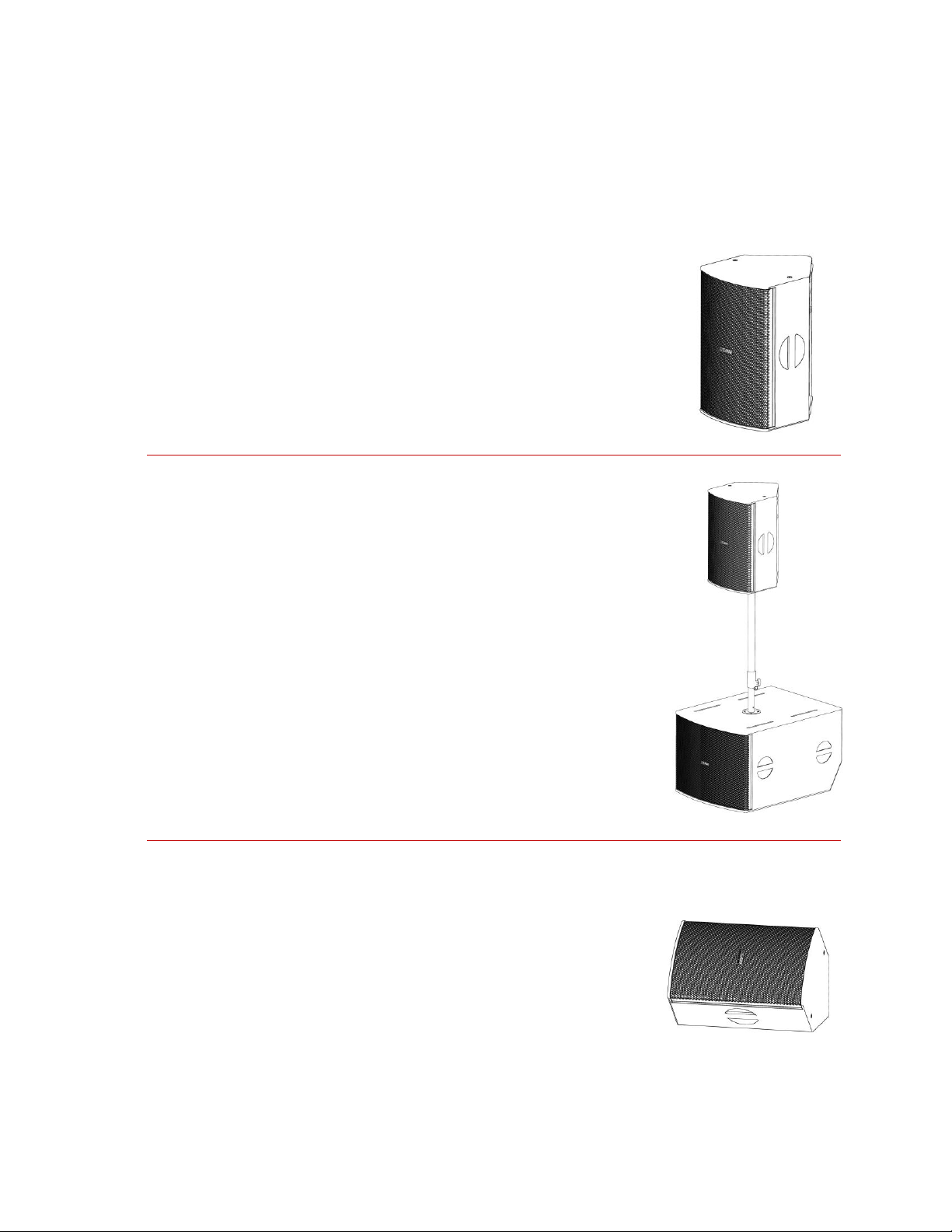
Redline™ System Overview
Qty
Item
1
Redline Series Product
1
Power Cable(dependent on products’ AC mains voltage)
115 V - Neutrik® powerCON® to Nema 15R plug
230 V - Neutrik® powerCON® to male Schuko plug
1
Redline Series Owner's Manual (this document)
1
Warranty Card
Redline is the newest powered point‐source loudspeaker from EAW. Drawing from EAW’s deep legacy
as a manufacturer of high‐end touring loudspeakers, Redline is designed specifically for the
professional audio user in corporate AV, rental & staging, and installation. Every feature is optimized to
make these users’ lives easier.
The Redline family consists of three models – a 12” two‐way, 15” two-way and 18” subwoofer. All
three models incorporate a complete amplifier and processing module, including over 1,250 watts of
Class‐D Power‐Factor‐Corrected bi‐amplified power (1,000 watts for the subwoofer). Our 12” and 15”
mains feature EAW’s signature Focusing™ for a pristine impulse response, and all Redline models
incorporate EAW’s new DynO™ dynamic optimization algorithms to maintain this fidelity at even the
highest output levels.
RL12 and RL15 mains each include three pre‐defined, pre‐tuned voicings for mains, monitor and mains
with sub configurations. Each of these mains features a symmetrical enclosure and swappable
amplifier module to easily form mirror‐image monitor pairs. RL18S subwoofers feature a push‐button
cardioid function that allows you to create perfect cancellation behind the stack with two loudspeakers
(one rotated). All Redline models feature 18‐gauge steel grilles, hyper‐black EAW logos and EAW’s
signature RoadCoat™ finish shared with many other EAW touring products such as Microwedges and
Adaptive Systems.
In short – Redline gives professional users what they need most: rapid setup, spectacular sound with
little fuss, application flexibility, and long‐term reliability, all wrapped in styling that radiates
professionalism.
Unpacking
You should have visually inspected the outside of the shipping carton and noted any damage on the
shipping bill you signed. After unpacking, if you find concealed damage to the loudspeaker, save the
packing materials for the carrier's inspection, notify the carrier immediately and file a shipping damage
claim. Although EAW will help in any way possible, it is always the responsibility of the receiving party
to file any shipping damage claim. The carrier will help prepare and file this claim.
Contents
Page 10
10
Functionality and Operation
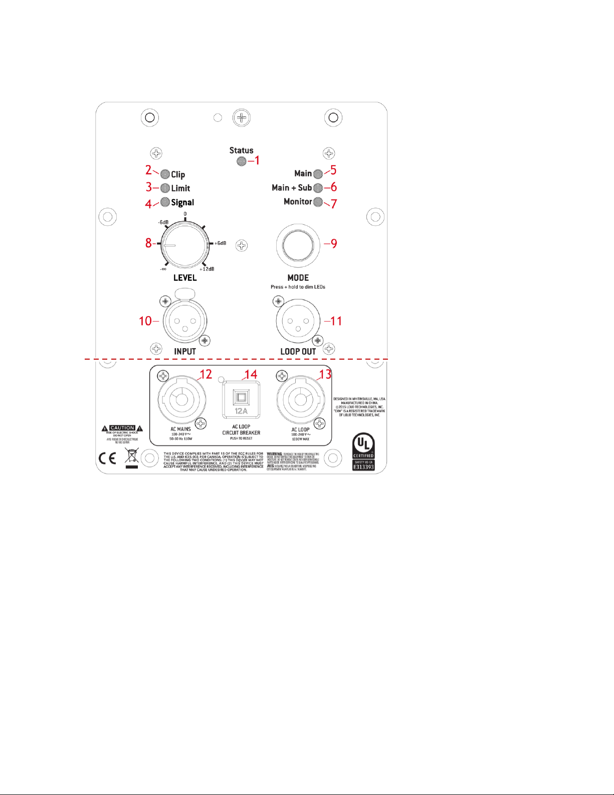
1
Status LED
Indicator for normal and fault status
2
Clip Indicator
Indicator for input signal clipping
3
Limit Indicator
Indicator for limiting of output signal
4
Signal Presence Indicator
Indicator for signal presence
5
‘Main’ voicing selection indicator
Indicates Main voicing is selected
6
‘Main + Sub’ voicing selection indicator
Indicates Main+ Sub voicing is selected
7
‘Monitor’ voicing selection indicator
Indicates Monitor voicing is selected
8
Input level attenuator
Controls the input signal level
9
Mode selection button
Selects between different voicings
10
XLR input
Connect Analog input signals
11
XLR Loop Through
Loop input signal to additional RL products, or other devices
12
AC Mains Input
Connect to AC mains supply as labeled
13
AC Mains Loop Through
Loop AC Mains for up to (4) additional RL products.
14
AC Loop Circuit Breaker
User Resettable, 12A(115 V), 6A(230V)
RL12/RL15 Rear Input Panel Connectors and Controls
Page 11
11
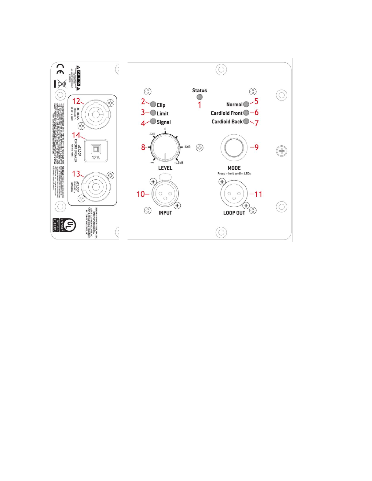
1
Status LED
Indicator for normal and fault status
2
Clip Indicator
Indicator for input signal clipping
3
Limit Indicator
Indicator for limiting of output signal
4
Signal Presence Indicator
Indicator for signal presence
5
‘Normal’ voicing selection indicator
Indicates Normal voicing is selected
6
‘Cardioid’ voicing selection indicator
Indicates Cardioid Front voicing is selected
7
‘Cardioid Back’ voicing selection indicator
Indicates Cardioid Back voicing is selected
8
Input level attenuator
Controls the input level
9
Mode selection button
Selects between different voicings
10
XLR input
Connect Analog input signals
11
XLR Loop Through
Loop input signal to additional RL products, or other devices
12
AC Mains Input
Connect to AC mains supply as labeled
13
AC Mains Loop Through
Loop AC Mains for up to (4) additional RL products.
14
AC Loop Circuit Breaker
User Resettable, 12A(115 V), 6A(230V)
RL18S Subwoofer Rear Input Panel Connectors and Control
Page 12

12
Audio Connections
Analog Audio
Connect the output from your line-level signal source to the XLR-3F INPUT connector on the rear
panel. This is an electronically balanced input. Users must provide their own XLR cables. The two
XLR-type connectors on the rear of each Redline series product, one female and one male, are
designed for professional audio signal levels, nominally 0 dBu (= 0.775 V). Normally, use the female
XLR as the signal input. Use the male XLR as a loop-thru output to connect the same signal input to
additional Redline products.
The wiring convention is as follows:
Pin 1: Shield
Pin 2: +/Hot
Pin 3: -/Cold
AC Mains Connection
Connect the supplied AC mains cord to the Neutrik® powerCON® socket on the rear of the
loudspeaker. Connect the other end to an AC mains supply receptacle, nominally 115 V 60 Hz or
230 V 50 Hz as labeled on the loudspeaker. If necessary, have a qualified electrician change the
cable plug as required for compatibility with the local ac mains receptacle.
WARNING: Before connecting a Redline loudspeaker to the AC mains supply,
completely turn down the input signal to the loudspeaker using the input level attenuator. If not,
there could be excessive and possibly damaging sound levels from the loudspeaker when
energized.
There is no power switch on the loudspeaker. When connected to the AC mains the loudspeaker
will be fully operational, with the output level controlled by the signal source feeding the
loudspeaker and level of the input attenuator.
Linking power
The Neutrik® powerCON® AC mains and AC loop connectors
are wired in parallel to provide an AC mains inlet and outlet
on each Redline product. The blue AC mains inlet mates with
a Neutrik® powerCON® NACFC3A (supplied). The white AC
mains outlet mates with a Neutrik® powerCON® NACFC3B.
Therefore, to loop the AC mains from enclosure to enclosure,
connect an AC mains jumper cable as shown (jumper is not
included with Redline series products).
Page 13

13
Fault Condition
Indication
User’s Next Steps
LED
Light length
Repeat Period
All components working
properly
Green LED
Solid Green LED
None
Amplifier is in protect
mode
Red LED flashing
short
fast
Change program material
(ensures no DC in signal).
Impedance Fault (short,
open)
Red LED flashing
short
slow
Allow speaker to cool
down then test drivers.
Excessive internal
temperature
Red LED flashing
long
slow
Reduce drive level and/or
cool down speaker.
AC Input Voltage out of
acceptable range
Red LED
Solid red LED.
Check AC power voltage.
Up to four additional RL12 or RL15’s can be looped in this fashion. Use an AC loop connector to
daisy-chain AC mains power from one enclosure to another. The maximum, continuous load must
not exceed 12A for the 115V version and 6A for the 230V version.
NOTE: The circuit breaker only protects the AC loop outlet, not the AC mains connector. If the
continuous load connected to the AC loop outlet exceeds the rated load, the circuit breaker will
trip. For this situation, reduce the connected load and then manually reset the circuit breaker.
Operating Indicators
Status
The Status LED is used to indicate the status of Redline series products, please refer to the chart below to
determine the current operating status.
Limit
The limiting parameters set in Redline Products are engineered to provide a high level of
protection for the drivers while maximizing sonic performance and output. The Limit indicator in
the rear input panel illuminates when limiting is occurring. If this is flashing occasionally, meaning
no more than once every 3 seconds or so, then levels are probably OK, but at maximum.
If this indicator is flashing more than once every 3 seconds or so, reduce the input signal level.
Clip
The Clip indicator on the rear panel illuminates if any of the Redline electronics are being driven
into clipping. This includes the entire signal chain from the input stage through the DSP. Clipped
signals can more easily damage drivers as they can raise the average signal level significantly with
a spectrum that differs from the input signal. If the Clip indicator is flashing this indicates an
Page 14

14
unacceptable overdrive in the system, reduce the input signal level or damage to the drivers is
likely to occur.
CAUTION: Electronic limiters cannot provide absolute protection against driver failure. Thus, if
limiting is occurring, it is a warning that excessive signal levels are being approached. It is NOT an
indication that the loudspeaker is successfully protecting itself.
Operating Limits
While the processing for Redline series products includes robust driver and amplifier protection
algorithms and circuits, it is ultimately the responsibility of the audio system operator to operate
the loudspeakers within their capabilities. This is the only way to ensure that loudspeakers are not
stressed beyond their limits to the point of damage or failure. Operation beyond their capabilities
usually includes, but is not limited to, one or more of the following conditions:
Severe amplifier clipping
Noticeable distortion
Mechanical noise (such as cones bottoming out)
The Redline products have both Limiter and signal indicators. It is recommended that the operator
have a meter display calibrated to indicate the level where the Limiting and Clipping point are and
thus be near to exceeding their capabilities
Adjusting the Output Level
Starting with the input level attenuator at -∞ (all the way to the left), turn the input attenuator
up until the desired volume is reached, but below the point where the CLIP and/or LIMITER ACTIVE
lights illuminate.
CAUTION: If there is no sound, turn down the signal source's output level before investigating
the problem. Do this to avoid excessive and possibly damaging sound levels from the loudspeaker.
CAUTION: Excessive clipping and limiting of the input signal should be avoided as it could result
in damage to loudspeaker transducers.
LED Dim
For aesthetically sensitive situations where the LED indicators of the rear of Redline may be
distracting, the LED light level can be reduced. To dim the LEDs, hold the ‘Mode’ button for 2
seconds. To restore the maximum LED brightness, repeat the same process, by holding down the
‘Mode’ button for two seconds. Note that for approximately one second after dimming or
restoring the rear-panel LEDs, the voicing mode cannot be changed. This occurs because the LED
state is being stored to non-volatile memory in order to persist through a power-cycle. This
function has no effect on audio output.
Page 15
15
Onboard Processing/Voicing
Voicing Options - RL12, RL15
RL15 and RL12 feature three distinct voicings to accommodate a wide range of applications. To
select voicings, simply press the ‘Mode’ button on the back panel until the desired voicing is
illuminated.
Main
Select the ‘Main’ voicing when using the RL12/15 without a subwoofer.
The ‘Main’ voicing optimizes internal processing to maximize low
frequency response for stand-alone full-range use.
Main + Sub
Select the ‘Main + Sub’ voicing when using RL12/15 with the RL18S
Subwoofer to create a three-way system. It optimizes overlap
frequencies between the main and the sub to maximize overall output
performance. This mode should also be used with pairing the RL12/15
with other companion subwoofers.
Monitor
Select the ‘Monitor’ voicing to optimize RL12/15 for use when placed on
the ground horizontally. This voicing compensates for acoustical
coupling with the ground, providing optimized performance when using
RL12/15 as a stage monitor.
Page 16

16
Voicing - RL18S
The RL18S subwoofer features three distinct voicings to accommodate a wide range of
applications. To selection voicings, simply press the ‘Mode’ button until the desired voicing is
illuminated. Normal mode provides maximum output performance. Cardioid mode provides low
frequency cancellation behind an array of subwoofers and can reduce greatly unwanted low
frequency energy from spilling onto a stage.
Normal
Select the ‘Normal’ voicing to optimize RL18S for standard
operation when used alone, or with other RL18S subwoofers for
maximum output performance.
Cardioid Front
When using 2 or more RL18S subwoofers in a cardioid
configuration, select the ‘Cardioid Front’ for the RL18S
which is oriented towards the intended coverage area (see
the “Cardioid Configurations” section in this manual for
more information on valid arrangements).
Cardioid Back
When using 2 or more RL18S subwoofers in a cardioid
configuration, select the ‘Cardioid Back’ for the RL18S which
is oriented away the intended coverage area. (See the
“Cardioid Configurations” section in this manual for more
information on valid arrangements)
Page 17

17
DynO™
DynO™ is a revolutionary processing technique
that allows EAW Engineers to maximize output
from a given amplifier – transducer combination.
As opposed to conventional limiting which simply
views amplifier output and driver power handling
in aggregate (i.e. a driver can handle 100 watts or
an amplifier can produce 500 watts), the DynO
process involves much more detail and
complexity. By studying the headroom of all electronic and acoustical devices frequency by
frequency and utilizing frequency‐dependent limiting algorithms in combination with more
traditional band-pass limiting, a system’s broadband headroom can be maximize regardless of the
input signal spectrum.
EAW Focusing™
Even in well-designed professional loudspeakers, inherent
sonic flaws such as phase plug reflections, horn
resonances and cone resonances can cause undesirable
audible artifacts. Implemented through advanced digital
signal processing, EAW Focusing™ generates complex
filters that correct these imperfections and improve the
transient response of a loudspeaker. This is accomplished
by isolating linear, time invariant and spatially consistent
anomalies in a loudspeaker’s response and eliminating
them through advanced processing. The result is a high
output, controlled loudspeaker that provides a pristine
transient response equal to that of a direct radiating
studio monitor.
Page 18

18
Redline Application Configurations
Removing the Red Strip
The red strip alongside the Redline products is adhered magnetically and
can be removed as needed for aesthetically critical situations.
To remove the red strip, carefully peel back the magnetic strip. Place the
red strip in a safe location so that it can be re-applied in for future
applications.
Rotating the horn
RL12 and RL15 feature a user rotatable horn, providing exceptional application flexibility and the
ability to maintain the 90o x 60o coverage pattern when the speaker is mounted horizontally. To
rotate the horn, please follow the steps outlined below.
1. Remove the red strip to access the retaining screws
securing the grill in place.
2. Remove the 10 retaining screws securing the grill in place
using a standard Philips head screwdriver.
3. Remove the HF horn/driver assembly by unscrewing their
retaining screws using a 3/16” hex key.
4. Carefully lift the HF horn/driver assembly from the baffle
5. Rotate the HF horn/driver assembly 90 degrees.*
6. Replace the HF horn/driver assembly back into the
enclosure and re-fasten the retaining screws
7. Replace the grille and re-fasten the retaining screws.
* The orientation of the horn can be determined by the
orientation of the horn throat opening. When the opening
is in the vertical orientation, the horn is in the default 90o x
60o configuration. If the opening is horizontal, the horn is in
the 60o horizontal x 90o vertical orientation.
Page 19

19
Creating Symmetrical Monitor Angles (Swapping Amplifier Modules)
Redline RL12 and RL15 products feature the ability to switch the amplifier to the opposite side of
the enclosure to create symmetrical monitor angles for mirror image pairs. To move an amplifier
to the opposite side of the loudspeaker
1. Disconnect the unit from AC supply and disconnect all analog
audio cabling.
2. Remove the 12 mounting screws using a standard Phillips head
screwdriver. Notice the top center screw indicated in the
diagram, this is not a mounting screw, but a jacking screw
location.
3. After removing the 12 screws, insert one of the standard
longer screws into the jacking screw location. This will help free
the amplifier from the loudspeaker cabinet.
4. Turn the mounting screw clockwise, pushing against the
loudspeaker and forcing the amplifier’s corner out. If the
amplifier remains fixed to the gasket it may be necessary to
use a flat head screwdriver to free the amplifier from the
loudspeaker.
5. Once free, carefully lift the amplifier from the loudspeaker and
disconnect the electrical leads at the coupling. Set the amplifier
module aside.
6. Follow the procedure above for the blank amplifier panel on the
opposite side of the loudspeaker.
7. Connect the electrical leads to the amplifier module.
8. Secure the amplifier by re-installing and tightening the 12
mounting screws.
9. Secure the blank panel by re-installing and tightening the 12
mounting screws remembering to reinsert the shorter jacking
screw in the top center position.
Page 20

20
Application Notes
Flying Redline from threaded mounting points
Redline attachment points are designed to accept M8 hardware. Always use a minimum of two
points to suspend any loudspeaker. See section on “Rigging” later in this manual for more
information.
Arraying RL12 and RL15
Redline loudspeakers can be arrayed in various ways. However, arraying loudspeakers requires
special consideration for the overall array’s mounting angle, projection pattern, rigging/mounting
method, and for system tuning adjustments. These issues can be significantly more complex than
when the loudspeakers are used individually. The recommendations in this section may not be
suitable for particular applications or for the desired sonic results. For assistance in configuring
Redline in an array, contact EAW’s Application Support Group.
Vertical Array
1. Non-Rotated Horn (90° horizontal
coverage): Use a 90° splay between
enclosure sides.
2. Rotated Horn (60° horizontal
coverage): Use a 60° splay between
enclosure sides.
If a different splay angle is needed for proper coverage, we suggest spacing the cabinets several
feet apart, creating an exploded array to reduce comb filtering at critical frequencies.
Horizontal Array
1. Rotated Horn (90° horizontal coverage): Orient
the enclosures so the LF drivers are adjacent
(i.e. enclosure bottom to bottom).
2. Use a 45° splay between the enclosure
bottoms.
As with vertical arrays, if a different splay angle is needed for proper coverage, we suggest spacing
the cabinets several feet apart, creating an exploded array to reduce comb filtering at critical
frequencies.
Recommended Accessories
For a list of recommended accessories, please see the ‘Redline Accessory Guide’ document,
available at www.eaw.com
Page 21

21
RL18S Standard Cardioid Configurations
The RL18S features push-button cardioid functionality, allowing two or more RL18S subwoofers to
be used together in a cardioid configuration. Cardioid functionality is possible in a number of
different physical configurations, demonstrated below. These configurations can be scaled by
adding equal numbers of front, and back facing subwoofers to achieve cardioid patterns with
additional SPL output capabilities.
Two RL18S Stacked Horizontal
Two RL18S subwoofers can be stacked, one on top of
another to achieve a cardioid coverage pattern. The
subwoofer facing towards the audience should be set to
‘Cardioid Front’ with the other subwoofer set to ‘Cardioid
Back’.
Two RL18S Side-by-Side Horizontal
Two RL18S can be placed side-by-side to achieve
cardioid coverage pattern. The subwoofer facing
towards the audience should be set to ‘Cardioid
Front’ with the other subwoofer set to ‘Cardioid
Back’.
Two RL18S Side-by-Side Vertical
Two RL18S can be placed side-by-side to achieve
cardioid coverage pattern. The subwoofer facing
towards the audience should be set to ‘Cardioid Front’
with the other subwoofer set to ‘Cardioid Back’.
Page 22

22
Other Cardioid Configurations
Rear Attenuation*
Rejection Distance
Forward Reduction
Rear Gain Setting
12 – 18 dB
10 ft/ 3 m
-1.5 dB
0 dB (unity)
1 ft / .3m
-6 dB
-6 dB (first line below 0)
It may be beneficial for the user to employ variants on the standard cardioid configurations in the
form of unequal front/rear-facing subwoofers and/or relative front/back subwoofer gain
adjustments. This allows the user to further tailor output and rejection levels to suit the needs of
their application.
Three RL18S – In situations where space permits three RL18S to be assembled in one array, a
cardioid configuration is still possible. Because the amount of forward- and rear-facing enclosures
are no longer even, however, a gain offset must be applied to the rear facing subwoofer to
maintain the same nominal rejection level as with the two-subwoofer configurations.
Maximum Rejection – The included cardioid presets are tailored to provide the optimal balance of
rejection and forward output. In this way, an array of two RL18S subwoofers can provide significant
rear rejection while sacrificing only 1.5 dB of forward gain as compared to two RL18S in an
omnidirectional configuration (both facing forward, on the default preset). The included preset is
also optimized to provide rejection at distances of approximately 10 feet from the stack.
However, the user may desire greater amounts of rejection at distances closer to the array, at the
expense of forward output. This can be easily accomplished by simply reducing the amount of gain
on the rear-facing subwoofer as follows:
* Rear rejection measurement at “Rejection Distance”, averaged across operating range. Rear
attenuation is heavily dependent upon acoustical environment and exact results may vary.
Rigging
Redline RL12 and RL15 are intended to be suspended via integral rigging
points, or ground-stacked. Redline RL18S is intended to be groundstacked only. It is the user’s responsibility to determine the viability and
safety for alternate methods and implement them accordingly.
NOTE: At a minimum, any suspended Redline loudspeaker must be flown
from the two top M8 rigging points. The third point on the rear of the
enclosure may be used to increase the down-tilt. Always observe load
de-rating when applying loads with lateral components to eyebolts. Use
hoist rings where necessary. NEVER SUSPEND ONE REDLINE ENCLOSURE
FROM ANOTHER – ALL FLOWN REDLINE ENCLOSURES MUST BE
SUPPORTED INDEPENDENTLY.
Page 23

23
Warnings
WARNING: Mounting or overhead suspension of any heavy load can result in serious injury and
equipment damage. This work should be done by qualified persons following safe rigging practices
in accordance with all applicable safety and construction standards. Such persons must determine
the required load ratings and design factors. They must determine the mounting or suspension
method that meets static, dynamic, shock, and any other load requirements. All such work must be
done in accordance with and in compliance with all federal, state, and local regulations governing
such work.
WARNING: If there is any question about the integrity or capability of any part to perform its
intended function when used to suspend or mount a loudspeaker, immediately remove it from
service for repair or replacement.
WARNING: Do not under any circumstances use a loudspeaker's handles to support the weight of
the loudspeaker except for their intended use: hand carrying. The handles are not rated to support
the load of the loudspeaker for temporary or permanent installation.
WARNING: Rigging loudspeakers is an extremely serious matter with potentially lethal
consequences should anything go wrong. It is of vital importance that this task is done by persons
qualified to do so and who have a full understanding of all factors involved, with safety as the
number one priority. Only persons with the knowledge of and experience with proper hardware
and safe rigging techniques should attempt to suspend or mount loudspeaker systems overhead.
For all questions involving loudspeaker rigging, consult a licensed, qualified professional Engineer
or Professional Rigger. All rigging work must be done in accordance with and in compliance with all
applicable regulations governing such work.
Reference Material
For detailed information about rigging, the following publications are recommended:
"Entertainment Rigging: A Practical Guide for Riggers, Designers, and Managers"
By Harry Donovan; Harry M. Donovan, 2002
"An Introduction to Rigging in the Entertainment Industry"
By Chris Higgs; Entertainment Technology Press, June 2002
"Rigging for Entertainment: Regulations and Practice"
By Chris Higgs; Entertainment Technology Press, April 2003
Page 24

24
Firmware Update Procedure
Redline series products are equipped with user upgradable firmware to accommodate future voicing
and DSP updates. To update the firmware, please follow the instructions below.
Firmware Update on RL12/RL15
1. Disconnect the unit from AC supply and disconnect all
analog audio cabling.
2. Remove the 12 mounting screws using a standard Phillips
head screwdriver. Notice the top center screw indicated in
the diagram, this is not a mounting screw, but a jacking
screw location.
3. If the amplifier remains fixed to the loudspeaker after
removing the 12 mounting screws, it is because the amplifier
to loudspeaker gasket is binding them together. To free
them, use the center jacking location to free the amplifier
from the loudspeaker.
4. To do so replace the keeper screw from the center location
with one of the mounting screws already removed.
5. Turn the mounting screw clockwise, pushing against the
loudspeaker and forcing the amplifier’s corner out. If the
amplifier remains fixed to the gasket it may be necessary to
jack another corner away from the loudspeaker.
6. Once free, carefully lift the amplifier from the loudspeaker
and disconnect the electrical leads at the coupling. Set the
amplifier module aside.
7. Locate the Micro USB input port at the top of the amplifier
and connect the user supplied micro cable to the amplifier.
8. Connect AC power to the amplifier module and follow the
firmware update quick start guide.
WARNING: Once AC power is applied to the amplifier
module, avoid direct contact with the protective cage
surround the amplifier.
9. When the firmware update is complete, disconnect AC power
from the amplifier, disconnect the USB cable, then re-secure
the amplifier module to the loudspeaker.
Page 25

25
Firmware Update - RL18S
The firmware update and amplifier removal procedure for the RL18S is identical to that of the
RL12/15, with the exception of the Micro USB port, which is located on the side of the amplifier,
rather than the top.
1. Disconnect the unit from AC supply and
disconnect all analog audio cabling.
2. Remove the 12 mounting screws using a
standard Phillips head screwdriver. Notice the
top center screw indicated in the diagram, this is
not a mounting screw, but a jacking screw
location.
3. If the amplifier remains fixed to the loudspeaker
after removing the 12 mounting screws, it is
because the amplifier to loudspeaker gasket is
binding them together. To free them, use the
top center jacking location to free the amplifier
from the loudspeaker.
4. To do so replace the keeper screw from the
center location with one of the mounting screws
already removed
5. Turn the mounting screw clockwise, pushing
against the loudspeaker and forcing the
amplifier’s corner out. If the amplifier remains
fixed to the gasket it may be necessary to jack
another corner away from the loudspeaker.
6. Once free, carefully lift the amplifier from the loudspeaker and disconnect the electrical leads
at the coupling. Set the amplifier module aside.
7. Locate the Micro USB input port at the side of the amplifier and connect the user supplied
micro cable to the amplifier.
8. Connect AC power to the amplifier module and follow the firmware update quick start guide.
WARNING: Once AC power is applied to the amplifier module, avoid direct contact with the
protective cage surround the amplifier.
9. When the firmware update is complete, disconnect AC power from the amplifier, disconnect
the USB cable, and then re-secure the amplifier module to the loudspeaker.
Page 26

26
Basic Field Troubleshooting and Repair
Loudspeaker difficulties usually fall into one of the following categories. The causes for
each problem are listed in the most likely order of probability.
No Sound or Low Output
1. Loudspeaker cables or connectors are miswired or faulty: Check all cabling. Refer to these
instructions for correct loudspeaker cable connections. The best way to check a suspect cable
is to swap it with a known good cable. Read the loudspeaker's input panel to verify correct
cable connections.
2. Electronic equipment is not turned on or level controls are not adjusted properly:
Make sure that all equipment in the signal path is powered up and that all controls are set to
appropriate levels for normal operation.
3. Loudspeaker is not working: Connect the signal cable to a known good loudspeaker
leaving all equipment set to the same levels. If the problem disappears, the loudspeaker is
probably not working. Contact EAW Service for appropriate troubleshooting.
Distorted Sound
1. The input to the internal amplifier is clipping: The input signal level is exceeding the limits of
your system and should be reduced in level.
2. Other electronic equipment is clipping: Ensure that no equipment in the signal chain is being
overdriven. For example: input(s) or summing bus in the mixing console, equalizers, etc.
3. Driver(s) not working properly: Contact EAW Service for appropriate troubleshooting.
Partial Sound (Some Frequency Bands Missing)
1. Incorrect EQ settings in the electronic equipment: Ensure all EQ settings and filters on the
mixing console or preamplifier and on other equipment are set for normal operation. Ensure
level controls on electronic crossovers and associated amplifiers are correctly set and that all
cables and connections for such equipment are working properly.
2. Incorrect processor configuration: Make sure the processor configuration is correct for the
loudspeaker and its intended mode of operation. This includes settings made using software
for powered loudspeakers.
3. Incorrect mode settings on the loudspeaker input panel. Ensure mode settings are correct for
the application.
4. Driver(s) not working properly: Contact EAW Service for appropriate troubleshooting.
Page 27

27
Rigging Problems
Because of the potential serious consequences and liabilities due to faulty rigging, contact
the EAW Service Department to determine the appropriate service solution for any
problems with the rigging hardware integral to the enclosure or EAW rigging accessories.
Enclosure and Integral Hardware
Enclosure problems, such as loose hardware, faulty joints, or other structural problems,
will usually be heard as distinct buzzes, rattles, or other unwanted noises. To test for
enclosure problems, use a sine wave signal manually swept on the loudspeaker. The
input level should be varied, because certain problems can be level as well as frequency
specific. It may be possible to field-repair some enclosure problems.
Cosmetics
While the paint finish and the wood used for the enclosures is of high quality and
durability, scuffs, marks, and other blemishes may appear from normal handling. For paint
touchup, use good quality latex paint. For a more permanent and cosmetically correct appearance,
contact the EAW Service Department for the paint specifications or to purchase small quantities for
touch-up. For cosmetically damaged wood, use common woodworking methods and materials as
appropriate for the damage.
Driver Service
A faulty driver will usually cause readily audible distortions or other unwanted noises. In
other cases, they may stop functioning. Use your ears and test signals or other sound
source to determine which one is at fault. The drivers can be field serviced by replacing the entire
driver or having the driver repaired (such as diaphragm replacement) by a qualified service
technician.
1. Access the drivers by removing the front grille.
2. Remove the LF driver or HF horn/driver assembly by unscrewing their retaining screws.
3. Lift the LF driver or HF horn/driver assembly from the baffle.
4. Disconnect the signal cable from the driver.
5. To reinstall or replace the LF driver and/or the HF horn/driver assembly, reverse the above
steps. Make sure that LF drivers are connected with the blue+ and black- signal wires and that
HF drivers are connected with the red+ and black- signal wires.
IMPORTANT: When reconnecting the signal wires to the driver, connect the colored wire to the
plus (+) terminal and the black wire to the (-) minus terminal.
Page 28

28
Powered Loudspeaker Electronics
Some faults with the electronics will normally be indicated by the ‘Status’ indicator on the
loudspeaker input panel and are described in the section labeled ‘Operating Indicators’. Others
should clearly be indicated by an outright malfunction in the sound output. Such malfunctions can
include:
1. No or very low sound output
2. Highly distorted sound
3. Poor frequency response, such as the loss of low or high frequencies
4. Intermittent sound
5. Excessive electronic noise
In the case of malfunctioning electronics, contact the EAW Service Department for
troubleshooting and repair instructions.
Internal Electronics and Wiring
Faulty electronics are serviced by replacing the entire amplifier module. A replacement module
consists of the power amplifiers, DSP board, power supply, connectors and indicators, all premounted on the amplifier panel. See ‘Swapping Amplifier Modules’ above for amplifier
replacement instructions.
Electrical Warnings
AC MAINS SUPPLY
WARNING: Read all instruction and cautionary notes concerning electrical power in the EAW
Loudspeaker Owner’s Manual.
Translations
ALIMENTATION SECTEUR
ATTENTION: Lisez toutes les instructions et notes de sécurité sur l'alimentation secteur, dans le
mode d'emploi de l'enceinte EAW.
ALIMENTAZIONE AC
ATTENZIONE: Leggere tutte le istruzioni e le avvertene riguardanti l'alimentazione elettrica,
incluse nel Manuale EAW Loudspeaker.
Page 29

29
FUENTE DE ALIMENTACIÓN
PRECAUCION: Lea todas las instrucciones y advertencias relativas a la corriente eléctrica que
aparecen en el manual de altavoces EAW.
NETZSTROMVERSORGUNG
WARNUNG: Lesen Sie alle Anweisungen und Sicherheitshinweise bezüglich der Netzspannung
in der EAW Lautsprecher Bedienungsanleitung.
AC Mains Cable
The AC mains cables supplied with the Redline products mate with the Neutrik® powerCON®
AC MAINS jack on the loudspeaker.
WARNING: Ensure that AC power supply has a properly grounded safety ground. Failure to
follow this warning could cause equipment damage, injury, or death.
Translations
Cordon secteur
ATTENTION : Il se peut que le format de la fiche secteur ne corresponde pas à celui de votre
situation géographique. Dans ce cas, faites appel à un électricien agréé pour qu'il remplace la
fiche par une autre du bon format. Respectez les normes électriques de câblage locales.
ATTENTION: Assurez-vous que la ligne secteur dispose d'une terre. Le non-respect de cette
précaution peut entraîner des dommages aux équipements et des accidents aux ersonnes
pouvant être fatals.
Cavo d'alimentazione AC
CAUTELA: Il connettore del cavo d'alimentazione AC fornto in dotazione potrebbe non essere
adeguato per le prese di corrente impiegate nell'area in cui il diffusore viene utilizzato. In
questo caso, contattare un elettricista qualificato per sostituire la presa di corrente con una
dotata di connessione adeguaa. Per il cablaggio, occorre seguire la codifica corretta utilizzata
nell'area d'utilizzo.
ATTENZIONE: Assicurarsi che la presa d'alimentazione sia correttamente collegata a terra. Il
mancato rispetto di tali avvertenze potrebbe causare danni all'apparechiatura, nonché
infortuni alle persone o la morte.
Cable de alimentación
PRECAUCION: El enchufe que viene en el cable de alimentación incluido puede que no encaje
en las salidas de corriente de su zona. Si ocurre esto, contacte con un electricista profesional
para que sustituya el enchufe problemático y lo cambie por uno adecuado para la salida de
corriente. Compruebe que se sigan todas las normativas de seguridad aplicables.
Page 30

30
PRECAUCION: Asegúrese que la fuente de alimentación tenga una conexión a tierra correcta.
El no cumplir con esta advertencia puede dar lugar a daños en el equipo, en las personas que lo
manejen o inclso la muerte.
Netzkabel
VORSICHT: Das mitgelieferte Netzkabel besitzt möglicherweise einen etzstecker, der nicht in
Ihre Steckdose passt. In diesem Fall können Sie sich von einem zugelassenen Elektrobetrieb
einen passenden Netzstecker unter Berücksichtigung der jeweils gültigen Vorschriften
montieren lassen.
WARNUNG: Stellen Sie sicher, dass er Schutzleiter der Netzsteckdose ein gute Verbindung zur
Erde hat. Nichtbeachtung dieses Hinweises kann zu Schäden am Equipment, zu Verletzungen
oder zum Tod führen.
Operating Temperature
The operating temperature range is 32° F to 113° F / 0°C to 45° C.
NOTE: When in operation and under load, maintain at least 6 in. of clearance below and 36 in.
of clearance behind all fan inlets and outlets.
Service, Inspection & Maintenance
General Service
All components in the Redline systems are designed to withstand the most rigorous and
demanding environments. Through regular operation it may still be necessary to replace
acoustical, electronic and mechanical components. The section below offers guidelines for
user-serviceable parts. If you have any questions about replacing components in Redline series
products, please contact EAW Service immediately and before performing the replacement.
CAUTION: These servicing instructions are for use by qualified service personnel only. To
reduce the risk of electric shock, do not perform any servicing other than that contained in the
operating instructions unless you are qualified to do so.
Rigging Service
Because of the potential serious consequences and liabilities due to faulty rigging, contact EAW
to determine the appropriate service solution for any rigging hardware concerns.
Routine Maintenance
DO NOT ATTEMPT TO OPEN, REPAIR OR SERVICE THE POWER PLANT; IT IS NOT USER-
SERVICEABLE.
Page 31

31
Internal Electronics and Wiring
The Redline Amplifier Module is not user-serviceable and must be sent to EAW for repair. In
the unlikely event of a failure of any amplifier or processing components, simply remove and
replace the entire Amplifier Module with a spare.
DO NOT ATTEMPT TO OPEN, REPAIR OR SERVICE THE AMPLIFIER MODULE.
Contacting EAW
We have attempted to make this manual as thorough as possible. However, feel free to
contact us with any further questions or comments for topics not covered.
Operating Questions
EAW Applications Support Group
Tel 508-234-6158
Tel 800-992-5013 (USA only)
Fax 508-234-6479
e-mail asg@eaw.com
Service Information
EAW® Service Department
Shipping
One Main Street Building 9
Whitinsville, MA 01588 USA
Tel 508-234-6158 x3
Tel 800-992-6158 x3 (USA only)
Fax 508-234-3776
e-mail service@eaw.com
General
Eastern Acoustic Works
One Main Street
Whitinsville, MA 01588 USA
Tel 508-234-6158
Tel 800-992-5013 (USA only)
Fax 508-234-6479
Web http://www.eaw.com
e-mail info@eaw.com
Page 32

32
 Loading...