

Page 1
NT SERIES
OWNER’S MANUAL
FULL- RANGE AND SUBWOOFER
LOUDSPEAKERS
Page 2

Section 1 Safety Precautions - READ THIS FIRST
1.1 Safety Instructions
Read and heed all warnings and safety instructions in the accompanying "EAW Loudspeaker
Manual" before using this product. Failure to follow this precaution may result in
equipment damage, personal injury, or death.
WARNING: The loudspeaker is supplied with an ac mains power cable. Depending on the
voltage model ordered, this cable is configured with the most common ac mains connector
for that voltage. If the connector is not compatible with the local ac mains receptacle,
employ a licensed electrician to re-configure the cable with the proper connector. Ensure
that ac power supply has a properly grounded safety ground. Failure to follow this warning
could cause equipment damage, injury, or death.
1 Consignes de Sécurité - À Lire en Premier
1.1 Instructions Relatives À la Sécurité
Lisez et respectez toutes les consignes de sécurité et les misesen garde fournies dans le
manuel des enceintes EAW avant d'utiliser ce produit. Le non-respect de ces consignes et
mises en garde peut entraîner des dommages aux équipements et des accidents aux
personnes pouvant être fatals.
ATTENTION: L'enceinte est fornie avec un cordon secteur. Selon la tension du modèle
commandé, ce câble est fourni avec la fiche la plus communément utilisée avec cette
tension. Si la fiche n'est pas compatible avec les prises secteur de votre région, faites appel à
un électricien agéé pour modifier le cordon secteur en fonction du format local. Vérifiez que
la fiche secteur dispose d'une mise à la terre. Le non-respect de la mise à la terre peut
entraîner des dommages aux équipements et des accidents aux personnes pouvant être fatal.
1 Precauzioni di Sicurezza - Da Leggere per Primo
1.1 Norme di Sicurezza
Prima di procedere con l'utilizzo del prodotto, leggere e rispettare ogni avvertenza e norma
di sicurezza riportata nel "Manuale EAW Loudspeaker". Il mancato rispetto di ogni
precauzone può causare danni all'apparecchiatura, nonché infortuni alle persone o la morte.
ATTENZIONE: Il diffusore è completo di cavo d'alimentazione AC fornito in dotazione. In
base la voltaggio del modello di diffusore acquistato, il cavo è configurato con l connettore
AC più adeguato. Nel caso in cui il connettore non sia compatibile con le prese di corrente
adottate nell'area d'impiego, rivolgersi ad un elettricista qualificato per ri-configurare il cavo
con il connettore più appropriato. Assicurarsi che a presa di corrente sia adeguatamente
collegata a terra. Il mancato rispetto di tali norme può causare danni all'apparecchiatura,
nonché infortuni alle persone o la morte.
ii
Loudspeaker Owner’s Manual
Congratulations on the purchase of your new EAW loudspeaker. You now own one of the
finest professional audio products available - the result of exceptional engineering and
meticulous craftsmanship. Please read these instructions to get the maximum performance
from your new loudspeaker.
Page 3

1 Precauciones de Seguridad - Lea Esto Primero
1.1 Instrucciones de Seguridad
Lea y oserve todos los avisos e instrucciones de seguridad que aparecen en el "Manual de
altavoces EAW" adjunto antes de usar este aparato. El no observar esta precaución puede dar
lugar a averías en el aparato, daños en las personas o incluso la muerte.
PRECAUION: El altavoz viene de fábrica con un cable de corriente. Dependiendo del
voltaje que use el modelo solicitado, este cable estará configurado con el enchufe más
habitual para ese tipo de corriente. Si ese enchufe no es compatible con su salida de
corriete, contacte con un electricista profesional para que cambie el enchufe del cable por
el tipo adecuado. Asegúrese de que la salida de corriente tenga una conexión a tierra
adecuada. El no observar esta advertencia puede dar lugar a averías en el aparato, años en
las personas o incluso la muerte.
1 Sicherheitshinweise - Lesen Sie Diesen Abschnitt Zuerst
1.1 Sicherheitsanweisungen
Lesen und beachten Sie alle Warnungen und Sicherheitsanweisungen der mitgelieferten
"EAW Lautsprecher Bedienungsanleitung" vor derBenutzung des Produkts. Nichtbeachtung
dieser Hinweise können möglicherweise zu Schäden am Equipment oder zu Verletzungen
bzw. zum Tod von Personen führen.
WARNUNG: Der Lautsprecher wird mit einem Netzkabel geliefert. Abhängig von der
jeweiligen Netzspanung wird das Kabel mit dem für die jeweilige Netzspannung gängigsten
Netzstecker ausgeliefert. Sollte der Netzstecker nicht in Ihre Netzsteckdose passen, dann
lassen Sie von einem zugelassenen Elektrobetrieb einen passenden Netzstecker montieren.
Stellen ie sicher, dass der Schutzkontakt der Netzsteckdose einen guten Kontakt zur Erde
hat. Nichtbeachtung dieser Hinweise können möglicherweise zu Schäden am Equipment
oder zu Verletzungen bzw. zum Tod von Personen führen.
1.2 EC Declaration of Conformity
Eastern Acoustic Works, as the manufacturer, hereby certifies that, in their delivered versions,
Product Models: NT26, NT29, NT56, NT59, and NTS22
Product Description: Self-powered loudspeaker
comply with the provisions of the standards listed below.
European Council Directive on Low Voltage, 73/23/EEC
EN 60065:2002 Audio, video, and similar electronic apparatus - safety requirements
European Council Directive on Electromagnetic Compatibility 89/336/EEC and 93/68/EEC
EN 55103-1:1997 Electromagnetic compatibility. Product family standard for audio, video,
audio-visual and entertainment lighting control apparatus for professional use - Emission
EN 55103-2:1997 Electromagnetic compatibility. Product family standard for audio, video,
audio-visual and entertainment lighting control apparatus for professional use - Immunity
Harmonized Standards:
EN55103-1 emissions The Technical Report/File is maintained at:
EN55103-2 immunity LOUD Technologies Inc. Worldwide Headquarters
EN60065 safety 16220 Wood-Red Road NE
Woodinville, WA 98072 USA
Authorized Representative: Tel: +1 425 892 6500
Kevin Cyrus Tel: +1 866 858 5832
Director of Compliance Fax: +1 425 487 4337
Loud Technologies, Inc. e-mail: info@eaw.com
November, 2005
iii
Page 4

NT Series Owner’s Manual
TABLE OF CONTENTS
Introduction
Section 1 Safety Precautions - READ THIS FIRST
1.1 Safety Instructions . . . . . . . . . . . . . . . . . . . . . . . . . . . . . . . . . . . . . . . . . . . . . . . . . . . . . . . . . . ii
1.2 EC Declaration of Conformity . . . . . . . . . . . . . . . . . . . . . . . . . . . . . . . . . . . . . . . . . . . . . . . . iii
Section 2 Unpacking
2.1 Contents. . . . . . . . . . . . . . . . . . . . . . . . . . . . . . . . . . . . . . . . . . . . . . . . . . . . . . . . . . . . . . . . . . . 2
Section 3 Quick Start
3.1 Initial Control Settings . . . . . . . . . . . . . . . . . . . . . . . . . . . . . . . . . . . . . . . . . . . . . . . . . . . . . . 2
3.2 Audio Connection . . . . . . . . . . . . . . . . . . . . . . . . . . . . . . . . . . . . . . . . . . . . . . . . . . . . . . . . . . 2
3.3 AC Mains Connection. . . . . . . . . . . . . . . . . . . . . . . . . . . . . . . . . . . . . . . . . . . . . . . . . . . . . . . 2
3.4 Adjusting the Output Level . . . . . . . . . . . . . . . . . . . . . . . . . . . . . . . . . . . . . . . . . . . . . . . . . 3
Section 4 Overview
4.1 Using the Loudspeaker . . . . . . . . . . . . . . . . . . . . . . . . . . . . . . . . . . . . . . . . . . . . . . . . . . . . . 7
4.2 Description . . . . . . . . . . . . . . . . . . . . . . . . . . . . . . . . . . . . . . . . . . . . . . . . . . . . . . . . . . . . . . . . 7
4.2.1 Models . . . . . . . . . . . . . . . . . . . . . . . . . . . . . . . . . . . . . . . . . . . . . . . . . . . . . . . . . . . . . . . . . . . . 8
4.2.2 Amplification . . . . . . . . . . . . . . . . . . . . . . . . . . . . . . . . . . . . . . . . . . . . . . . . . . . . . . . . . . . . . . 8
Section 5 Physical Installation
5.1 Mounting/Rigging. . . . . . . . . . . . . . . . . . . . . . . . . . . . . . . . . . . . . . . . . . . . . . . . . . . . . . . . . . 8
5.1.1 Mounting Point Working Load Limits . . . . . . . . . . . . . . . . . . . . . . . . . . . . . . . . . . . . . . . . 9
5.2 Application Configurations. . . . . . . . . . . . . . . . . . . . . . . . . . . . . . . . . . . . . . . . . . . . . . . . . . 9
5.2.1 Full-Range Loudspeaker . . . . . . . . . . . . . . . . . . . . . . . . . . . . . . . . . . . . . . . . . . . . . . . . . . . . 9
5.2.2 Subwoofer. . . . . . . . . . . . . . . . . . . . . . . . . . . . . . . . . . . . . . . . . . . . . . . . . . . . . . . . . . . . . . . . . 10
5.2.3 Stage Monitor. . . . . . . . . . . . . . . . . . . . . . . . . . . . . . . . . . . . . . . . . . . . . . . . . . . . . . . . . . . . . . 10
5.2.4 Moving the Amplifier Module . . . . . . . . . . . . . . . . . . . . . . . . . . . . . . . . . . . . . . . . . . . . . . . 10
5.3 Configuring Arrays . . . . . . . . . . . . . . . . . . . . . . . . . . . . . . . . . . . . . . . . . . . . . . . . . . . . . . . . . 11
5.3.1 Center of Gravity . . . . . . . . . . . . . . . . . . . . . . . . . . . . . . . . . . . . . . . . . . . . . . . . . . . . . . . . . . . 11
5.3.2 Vertical Array. . . . . . . . . . . . . . . . . . . . . . . . . . . . . . . . . . . . . . . . . . . . . . . . . . . . . . . . . . . . . . . 11
5.3.3 Horizontal Array. . . . . . . . . . . . . . . . . . . . . . . . . . . . . . . . . . . . . . . . . . . . . . . . . . . . . . . . . . . . 11
Section 6 Electrical Installation
6.1 Audio Signal Connection. . . . . . . . . . . . . . . . . . . . . . . . . . . . . . . . . . . . . . . . . . . . . . . . . . . . 12
6.1.1 Input Panel . . . . . . . . . . . . . . . . . . . . . . . . . . . . . . . . . . . . . . . . . . . . . . . . . . . . . . . . . . . . . . . . 13
6.1.2 Loop Connector. . . . . . . . . . . . . . . . . . . . . . . . . . . . . . . . . . . . . . . . . . . . . . . . . . . . . . . . . . . . 13
6.2 System Gain . . . . . . . . . . . . . . . . . . . . . . . . . . . . . . . . . . . . . . . . . . . . . . . . . . . . . . . . . . . . . . . 13
6.2.1 Level Control. . . . . . . . . . . . . . . . . . . . . . . . . . . . . . . . . . . . . . . . . . . . . . . . . . . . . . . . . . . . . . . 13
6.3 AC Mains Connection. . . . . . . . . . . . . . . . . . . . . . . . . . . . . . . . . . . . . . . . . . . . . . . . . . . . . . . 14
6.3.1 AC Mains Supply . . . . . . . . . . . . . . . . . . . . . . . . . . . . . . . . . . . . . . . . . . . . . . . . . . . . . . . . . . . 14
6.3.2 AC Mains Cable . . . . . . . . . . . . . . . . . . . . . . . . . . . . . . . . . . . . . . . . . . . . . . . . . . . . . . . . . . . . 15
6.3.3 Power On / Off . . . . . . . . . . . . . . . . . . . . . . . . . . . . . . . . . . . . . . . . . . . . . . . . . . . . . . . . . . . . . 16
6.4 Operating Controls - Full-Range Loudspeakers. . . . . . . . . . . . . . . . . . . . . . . . . . . . . . . . 17
6.4.1 Setting the HPF (High Pass Filter) . . . . . . . . . . . . . . . . . . . . . . . . . . . . . . . . . . . . . . . . . . . . 17
6.4.2 Setting the Operating Mode . . . . . . . . . . . . . . . . . . . . . . . . . . . . . . . . . . . . . . . . . . . . . . . . 17
6.5 Operating Controls-Subwoofer . . . . . . . . . . . . . . . . . . . . . . . . . . . . . . . . . . . . . . . . . . . . . . 18
6.5.1 Setting the Gain Switch . . . . . . . . . . . . . . . . . . . . . . . . . . . . . . . . . . . . . . . . . . . . . . . . . . . . . 18
6.5.2 Setting the Polarity . . . . . . . . . . . . . . . . . . . . . . . . . . . . . . . . . . . . . . . . . . . . . . . . . . . . . . . . . 18
iv
Page 5

v
Section 7 Operation
7.1 Operating Limits . . . . . . . . . . . . . . . . . . . . . . . . . . . . . . . . . . . . . . . . . . . . . . . . . . . . . . . . . . . 19
7.1.1 Operator Responsibility. . . . . . . . . . . . . . . . . . . . . . . . . . . . . . . . . . . . . . . . . . . . . . . . . . . . . 19
7.2 Adjusting the Output Level . . . . . . . . . . . . . . . . . . . . . . . . . . . . . . . . . . . . . . . . . . . . . . . . . 19
7.3 Operating Indicators. . . . . . . . . . . . . . . . . . . . . . . . . . . . . . . . . . . . . . . . . . . . . . . . . . . . . . . . 19
7.3.1 Limiter Active . . . . . . . . . . . . . . . . . . . . . . . . . . . . . . . . . . . . . . . . . . . . . . . . . . . . . . . . . . . . . . 19
7.3.2 Clip. . . . . . . . . . . . . . . . . . . . . . . . . . . . . . . . . . . . . . . . . . . . . . . . . . . . . . . . . . . . . . . . . . . . . . . . 19
7.3.3 IMPORTANT: Operator Response . . . . . . . . . . . . . . . . . . . . . . . . . . . . . . . . . . . . . . . . . . . . . 19
7.3.4 Amplifier Status . . . . . . . . . . . . . . . . . . . . . . . . . . . . . . . . . . . . . . . . . . . . . . . . . . . . . . . . . . . . 20
7.3.5 Signal Present. . . . . . . . . . . . . . . . . . . . . . . . . . . . . . . . . . . . . . . . . . . . . . . . . . . . . . . . . . . . . . 20
7.4 Signal Processing. . . . . . . . . . . . . . . . . . . . . . . . . . . . . . . . . . . . . . . . . . . . . . . . . . . . . . . . . . . 20
7.4.1 Internal Signal Processing . . . . . . . . . . . . . . . . . . . . . . . . . . . . . . . . . . . . . . . . . . . . . . . . . . 20
7.4.2 External Signal Processing . . . . . . . . . . . . . . . . . . . . . . . . . . . . . . . . . . . . . . . . . . . . . . . . . . 20
7.4.3 Limiters. . . . . . . . . . . . . . . . . . . . . . . . . . . . . . . . . . . . . . . . . . . . . . . . . . . . . . . . . . . . . . . . . . . . 20
Section 8 Maintenance and Service
8.1 Maintenance. . . . . . . . . . . . . . . . . . . . . . . . . . . . . . . . . . . . . . . . . . . . . . . . . . . . . . . . . . . . . . . 21
8.2 General Service . . . . . . . . . . . . . . . . . . . . . . . . . . . . . . . . . . . . . . . . . . . . . . . . . . . . . . . . . . . . 21
8.2.1 AC Mains Fuse . . . . . . . . . . . . . . . . . . . . . . . . . . . . . . . . . . . . . . . . . . . . . . . . . . . . . . . . . . . . . 21
8.3 Field Troubleshooting. . . . . . . . . . . . . . . . . . . . . . . . . . . . . . . . . . . . . . . . . . . . . . . . . . . . . . . 24
8.4 Driver Service . . . . . . . . . . . . . . . . . . . . . . . . . . . . . . . . . . . . . . . . . . . . . . . . . . . . . . . . . . . . . . 24
8.5 Amplifier Service . . . . . . . . . . . . . . . . . . . . . . . . . . . . . . . . . . . . . . . . . . . . . . . . . . . . . . . . . . . 25
8.5.1 Amplifier Modules. . . . . . . . . . . . . . . . . . . . . . . . . . . . . . . . . . . . . . . . . . . . . . . . . . . . . . . . . . 25
8.5.2 NT Amplifier Replacement Modules and Dip Switch Settings . . . . . . . . . . . . . . . . . . 25
8.5.3 Replacing the Amplifier Module . . . . . . . . . . . . . . . . . . . . . . . . . . . . . . . . . . . . . . . . . . . . . 25
Section 9 Block Diagram
9.1 Block Diagram . . . . . . . . . . . . . . . . . . . . . . . . . . . . . . . . . . . . . . . . . . . . . . . . . . . . . . . . . . . . . 26
Page 6
Section 2 Unpacking
2.1 Contents
Qty Item
1 NT Series Product
1 Power Cable (dependent on product's ac mains rating)
115 V - Neutrik PowerCon to Nema 15R plug
230 V - Neutrik PowerCon to male Schuko plug
1 Owner's Manual (this document)
1 EAW Loudspeaker Owner's Manual
1 Warranty Card
Section 3 Quick Start
If you are in a hurry or are knowledgeable about using powered loudspeakers, these Quick
Start instructions provide the details particular to the NT Series loudspeakers. For the
instructions in this section, refer to the accompanying Figures.
3.1 Initial Control Settings
Use these nominal settings for the rear panel switches.
Full-Range with no subwoofer
HPF 55 Hz
Mode Normal
Full-Range with subwoofer
HPF 110 Hz
Mode Normal
Subwoofer
Gain 0 dB
Polarity Normal
WARNING: Before connecting an NT loudspeaker to the ac
mains supply, completely turn down the input signal to
the loudspeaker using the signal source's output level
(master volume control or other output level control). If
not, there could be excessive and possibly damaging sound
levels from the loudspeaker when energized.
3.2 Audio Connection
Connect the output from your line-level signal source to
the XLR-3F Input connector on the rear panel. This is an
electronically balanced input.
3.3 AC Mains Connection
Connect the supplied ac mains cord to the Neutrik
PowerCon socket on the rear of the loudspeaker. Connect
the other end to an ac mains supply receptacle, nominal 115
V 60 Hz or 230 V 50 Hz as labeled on the loudspeaker. If
necessary, have a qualified electrician change the cable plug
as required for compatibility with the local ac mains
receptacle.
2
Page 7
CAUTION: There is no power switch on the loudspeaker. When connected to the ac mains
the loudspeaker will be fully operational, with the output level controlled by the signal
source feeding the loudspeaker.
3.4 Adjusting the Output Level
With a source program playing, gradually turn up the level of your signal source until the
desired volume is reached but below the point where the CLIP and/or LIMITER lights
illuminate.
CAUTION: If there is no sound, turn down the signal source's output level before
investigating the problem. Do this to avoid excessive and possibly damaging sound levels
from the loudspeaker.
3 Mise en ŒUVRE
Si vous êtes pressé ou déjàfamiliarisé avec l'utilisation des enceintes actives, ces instructions
de mise en œuvre vous donneront les détails spécifiques aux enceintes de la gamme NT
Series. Pour les instructions de cette section, consultez les figures.
3.1 Réglages Initiaux
Utiliez ces réglages de face arrière.
Large bande sans Subwoofer
HPF 55 Hz
Mode Normal
Large bande avec Subwoofer
HPF 110 Hz
Mode Normal
Subwoofer
Gain 0 dB
Polarité Normale
ATTENTION : Avant de connecter une enceinte NT au secteur,
coupez le signal rrivant en entrée de l'enceinte en réglant le
niveau de sortie de la source au minimum (réglage de niveau
général Master ou tout autre réglage de niveau de sortie).
Dans le cas contraire, le niveau sonore risque d'être excessif,
ce qui peut détruire l'encinte lors de sa mise sous tension.
3.2 Connexions Audio
Connectez la sortie de la source de signal à niveau ligne à
l'entrée XLR femelle 3 broches de la face arrière. Cette entrée
est à symétrie électronique.
3.3 Raccordement au Secteur
Connectez le crdon secteur fourni à l'embase Neutrik
PowerCon, située en face arrière de l'enceinte. Connectez
l'autre extrémité à une prise secteur, avec une tension de 115
V 60 Hz ou 230 V 50 Hz, indiquée sur l'enceinte. Si
nécessaire, faites appel à un électricien aréé pour modifier la
fiche secteur en fonction du format utilisé dans votre région.
3
Page 8
ATTENTION : L'enceinte n'est pas équipée d'un interrupteur secteur. Lorsque l'enceinte est
connectée au secteur, celle-ci est opérationnelle et son niveau est contrôlé pr le signal source
alimentant l'enceinte.
3.4 Référence du Niveau de Sortie
Utilisez un signal source de référence, augmentez progressivement son niveau jusqu'à
obtenir le niveau souhaité en veillant à rester sous le point où la Led d'écrêtage CLIP et/ou
d limitation LIMITER s'allume.
ATTENTION: En absence de son, commencez par diminuer le niveau de sortie de la source
avant de rechercher le problème. Ceci évite la présence de tout niveau sonore excessif et
dangereux dans l'enceinte.
3 Guida Rapida
Se ai già esperienza nell'impiego di diffusori attivi, o se desideri utilizzarlo da subito, questa
Guida Rapida fornisce ogni dettaglio utile per l'impiego dei diffusori NT Series. Per le
istruzioni di questa sezione, fare riferimento alle figure.
3.1 Imposazioni Iniziali dei Controlli
Usa queste regolazioni nominali per gli switches del pannello posteriore.
Full-Range senza subwoofer
HPF 55 Hz
Mode Normal
Full-Range con subwoofer
HPF 110 Hz
Mode Normal
Subwoofer
Gain 0 dB
Polarity Normal
ATTENZIOE: Prima di collegare il diffusore NT alla presa di
alimentazione, abbassa completamente il livello del segnale
in ingresso, agendo sul controllo di livello d'uscita della
sorgente del segnale (controllo Master Volume o altri
controlli di livello d'uscita. In caso contrario, alimentando il
diffusore potrebbero verificarsi livelli di segnale eccessivi e
potenzialmente pericolosi.
3.2 Connessione Audio
Collega l'uscita di linea della sorgente del segnale all'ingresso
XLR-3F presente nel pannello posteriore Questo ingresso è
bilanciato elettronicamente.
3.3 Connessione di Alimentazione AC
Collega il cavo di alimentazione AC fornito in dotazione al
connettore Neutrik PowerCon presente nel pannello
posteriore del diffusore. Collega l'altra estremità del cav ad una
presa di corrente AC (115 V 60 Hz o 230 V 50 Hz, come
4
Page 9
indicato nell'etichetta presente nel diffusore). Se necessario, rivolgersi ad un elettricista
qualificato per cambiare la spina del cavo, in base ai requisiti di compatibilità alle prese
d'alimntazione AC utilizzate nell'area d'impiego.
CAUTELA: Il diffusore non dispone di un interruttore per l'attivazione. Collegando il cavo
di alimentazione alla presa di corrente, il diffusore si attiverà: il livello d'uscita è
controllabile dalla sorgente el segnale.
3.4 Regolare il Livello D’uscita
Con il segnale in esecuzione, aumenta gradualmente il livello della sorgente sonora fino a
raggiungere il volume desiderato, prestando attenzione a non far attivare gli indicatori CLIP
e/o LIMITER.
CAUTELA: S il diffusore non emette alcun suono, assicurati di abbassare il livello d'uscita
della sorgente sonora, prima di investigare sulle cause del problema. In questo modo eviterai
la generazione di eventuali livelli di segnale eccessivi e dannosi da parte deldiffusore.
3 Inicio Rapido
Si quiere empezar a usar la unidad inmediatamente o si ya tiene un cierto conocimiento acerca
del uso de altavoces autoamplificados, en estas instrucciones de Inicio Rápido encontrará los
detalles relativos a estos altavoces N Series. Para comprender las instrucciones de esta sección,
consulte las figuras que se acompañan.
3.1 Ajustes de Control Iniciales
Utilice estos ajustes nominales para los interruptores del
panel trasero.
Rango completo sin subwoofer
HPF 55 Hz
Mode Normal
Rango completo con subwoofer
HPF 110 Hz
Mode Normal
Subwoofer
Gain 0 dB
Polarity Normal
PRECAUCION: Antes de conectar uno de estos altavoces
NT a la salida de corriente, reduzca al mínimo o anule la
señal de entrada que va a estos altavoces usndo el nivel de
salida de la fuente de señal (control de volumen master u
otro control de nivel de salida). En caso contrario, podrían
llegar a producirse niveles de sonido excesivos y
posiblemente dañinos en el momento de encender los
altavoces.
3.2 Conxion Audio
Conecte la salida de su fuente de señal de nivel de línea al
conector de entrada XLR-3F del panel trasero. Esta es una
entrada balanceada electrónicamente.
5
Page 10
3.3 Conxion de Corriente
Conecte el cable de alimentación incluido a la toma Neutrik owerCon de la parte trasera del
altavoz. Conecte el otro extremo a una salida de corriente, con un voltaje nominal de 115 V
60 Hz ó 230 V 50 Hz dependiendo de lo que aparezca indicado en el propio altavoz. Si es
necesario, haga que un electricista profesinal cambie el tipo de enchufe del cable caso de
que no encaje en su salida de corriente.
PRECAUCION: En este altavoz no hay ningún interruptor de encendido. Cuando lo conecte
a la corriente ya quedará totalmente operativo, con el nivel de salida controldo por la fuente
de señal que tenga conectada.
3.4 Ajuste del Nivel de Salida
Mientras se reproduce un programa fuente, suba gradualmente el nivel de su fuente de señal
hasta llegar al nivel de volumen que quiera, pero en un punto antes de que se ilumine los
pilotos CLIP y/o LIMITER.
PRECAUCION: Si no escucha el sonido, reduzca el nivel de salida de la fuente de señal antes
de investigar cual es el problema. El hacer esto evitará la entrada de niveles de sonido
excesivos y posiblemente dañinos al altavo.
3 Schnellanletung
Falls Sie sich in Eile befinden oder bereits mit der Nutzung aktiver Lautsprecher vertraut sind,
können Sie dieser Schnellanleitung produktspezifische Details zu den Lautsprechern der NT
Serie entnehmen. Für die Anweisungen in diese Kapitel finden
Sie entsprechende Abbildungen.
3.1 Anfangseinstellungen
Stellen Sie die Schalter auf der Rückseite auf die folgenden
Positionen (nominale Einstellungen).
Full-Range-Betrieb ohne Subwoofer
HPF 55 Hz
Mode Normal
Full-Range-Betrieb mit ubwoofer
HPF 110 Hz
Mode Normal
Subwoofer
Gain 0 dB
Polarity Normal
WARNUNG: Stellen Sie das Ausgangssignal der Signalquelle
(z.B. Masterregler eines Mischpultes) auf den kleinsten Wert,
bevor Sie den NT Lautsprecher an das Stromnetz anschließen.
Da ieses Signal zum Lautsprecher geschickt wird, könnten bei
starkem Quellsignal extrem bzw. schädliche Ausgangspegel
von der Box produziert werden, wenn diese mit Netzstrom
versorgt wird.
3.2 Audioanschluss
Verbinden Sie die Ausgangsbuchse Ihrer Linepegeluelle mit
der 3-poligen Eingangsbuchse auf der Rückseite der Box.
Dieser Eingang ist elektronisch symmetriert.
6
Page 11

3.3 Anschluss an Das Stromnetz
Stecken Sie das eine Ende des mitgelieferten Netzkabels in die Neutrik PowerCon Buchse auf
der Rückseite des Latsprechers. Stecken Sie den Stecker am anderen Ende in die
Netzsteckdose, die eine nominale Netzspannung von 230 V 50 Hz oder 115 V 50 Hz liefert
(muss mit den Angaben auf der Rückseite des Lautsprechers übereinstimmen). Falls
notwendig, kann ein zugelassner Elektrobetrieb einen anderen Netzstecker anbringen.
VORSICHT: Der Lautsprecher besitzt keinen Netzschalter. Wenn der Lautsprecher an die
Netzspannung angeschlossen ist, ist der Lautsprecher im Betriebszustand und gibt alle an
seiner Eingangsbuchse aliegenden Signale wieder.
3.4 Einstellung des Ausgangspegels
Schicken Sie ein Signal mit normalem Betriebspegel in die Box und drehen Sie den
Pegelregler der Quelle langsam bis zum gewünschten Wert auf, aber nur maximal bis die
CLIP und/oder LIMITER LED ufleuchtet. Nun nehmen Sie den Pegel ein wenig zurück.
VORSICHT: Wenn die Box kein Signal wiedergibt, drehen Sie den Pegelregler der
Signalquelle ganz zu, bevor Sie sich an die Fehlersuche machen. Damit werden extrem laute
und möglicherweise schädliche Lutsprecherausgangspegel vermieden.
Section 4 Overview
This loudspeaker is intended for professional use. The construction, components, and hardware
have been designed to provide robust, reliable performance for its intended application.
Please ensure that you fully understand proper installation and operation before use.
4.1 Using the Loudspeaker
You will need to perform the following general tasks to properly put the loudspeaker into
service. The details for each task are provided in this manual.
1. Design and install a rigging or mounting system to support the loudspeaker in its
intended location and aimed in the desired direction.
2. Connect a line level audio signal to the loudspeaker.
3. Connect the loudspeaker to an ac mains supply as specified for the particular model.
4. Set-up and adjust system gain, signal processing, and limiting, as needed to
maximize the loudspeaker's performance.
5. Provide training to operate the loudspeaker within its limits.
6. Provide regular inspection and maintenance to maintain the integrity of the
installation and the performance of the loudspeaker system.
4.2 Description
The NT Series of loudspeakers represents true breakthrough technology with Gunness
Focusing™. In basic form, NT loudspeakers are compact, self-powered, and extremely
lightweight while providing the exceptionally high output capabilities required for
professional applications. However, to complement these features, new DSP (digital signal
processing) technology corrects inherent problems with compression driver phase plugs and
horns as well as the LF drivers. This processing is called Gunness Focusing™ after its inventor
David Gunness, EAW's Director of R&D. Gunness Focusing™, along with the highest quality
amplification, affords sonic performance comparable to the highest quality, direct radiating,
studio monitors but at much higher output levels.
7
Page 12

NT loudspeakers are designed to meet the requirements and demands of portable
applications as well as permanent installations. The integral electronics are based on proven,
high efficiency amplifier technology, with field-replaceable amplifier modules. The
loudspeakers need to be connected to an ac mains supply and a line level audio signal. The
internal DSP is factory preset to provide correct and consistent performance.
4.2.1 Models
The 2-way NT loudspeakers are available in both 12-inch and 15-inch LF driver formats.
Different beamwidths are offered to meet typical coverage requirements in their intended
applications. The trapezoidal design of the enclosures makes them easy to use as a main PA
loudspeaker or as a floor wedge for stage monitor applications.
A companion NT subwoofer is engineered to complement the NT full-range loudspeakers.
It extends the low frequency response of an NT full-range system and increases the output
capabilities at low frequencies. The drivers are installed so one is facing into the enclosure,
but connected with opposite polarity so both cones move in the same direction. At high
output levels each cone "loads" the other in the opposite direction to smooth out any
mechanical asymmetries. The result is significantly reduced distortion.
NT Models:
4.2.2 Amplification
As is true of all professional loudspeaker systems, the performance of the NT Series
loudspeakers depends on amplifiers delivering an adequate supply of clean power. To
maximize performance, the full-range loudspeakers are bi-amplified, meaning the LF and HF
drivers each have their own signal processing and built-in, high-efficiency amplifier. The
subwoofer is dual-amplified, meaning each driver has its own, built-in, high efficiency
amplifier.
Section 5 Physical Installation
5.1 Mounting/Rigging
Read and heed all warnings and safety instructions in the supplied "EAW Loudspeaker
Manual" before using this product. Failure to follow this precaution may result in
equipment damage, personal injury, or death.
NOTE: The CSA (Canadian Standards Association) approval rating does not include any
evaluation of mounting / rigging capabilities.
8
Loudspeaker
Full-range
Subwoofer
LF Amplifier HF Amplifier
1000 W
2x 1000 W
500 W
N/A
Full-range
NT26
NT29
NT56
NT59
Subwoofer
NTS22
Nominal
Beamwidths H x V
60º x 45º
90º x 45º
60º x 45º
90º x 45º
N/A
LF Driver
12 in cone, 3 in voice coil 3 in / 1.4 in exit compression driver
12 in cone, 3 in voice coil
15 in cone, 4 in voice coil
15 in cone, 4 in voice coil
2x 12 in cone, 4 in voice coil
3 in / 1.4 in exit compression driver
3 in / 1.4 in exit compression driver
3 in / 1.4 in exit compression driver
H F Driver
N/A
Page 13

5.1 Montaqge/Installation
ATTENTION : Lisez et respectez toutes les consignes de sécurité et toutes les mises en garde
dans le manuel de l'enceinte EAW avant d'utilisr ce produit. Le non-respect de ces précautions
peut entraîner des dommages aux équipements et des accidents aux personnes pouvant être
fatals.
5.1 Montaggio/Rigging
ATTENZIONE: Prima di procedere con l'utilizzo del prodotto, è necessario leggere e rispettar
ogni avvertenza e norma di sicurezza riportata nel "Manuale EAW Loudspeaker" fornito in
dotazione. Il mancato rispetto di ogni precauzione può causare danni all'apparecchiatura,
nonché infortuni alle persone o la morte.
5.1 Montaje/Anclaje
PRECAUCION: Lea yobserve todos los avisos e instrucciones de seguridad que aparecen en el
"Manual de altavoces EAW" adjunto antes de usar este aparato. El no observar esta precaución
puede dar lugar a averías en el aparato, daños en las personas o incluso la muerte.
5.1 Montge/Aufhängung(Rigging)
WARNUNG: Lesen und beachten Sie alle Warnungen und Sicherheitshinweise in der
mitgelieferten "EAW Lautsprecher Bedienungsanleitung" bevor Sie das Produkt benutzen.
Nichtbeachtung dieser Hinweise können möglicherweise zu Schäden am quipment oder zu
Verletzungen bzw. zum Tod von Personen führen.
5.1.1 Mounting Point Working Load Limits
Enclosure Oriented Horizontally: NT's integral mounting points and fly tracks are designed
to support only the weight of their own loudspeaker with suitable, external hardware. This
means that each NT loudspeaker must be supported independently of any other NT
loudspeaker and any other loads.
Enclosure Oriented Vertically: NT's integral mounting points and fly tracks are designed to
support two loudspeakers with suitable, external hardware. This means that each NT
loudspeaker can be supported from the fly-tracks of the loudspeaker above it.
5.2 Application Configurations
5.2.1 Full-Range Loudspeaker
The NT loudspeaker is intended for use in several mounting configurations:
Placement in typical loudspeaker locations, such as on
the floor, a stage, a subwoofer stack,
or other stable, solid platform.
9
Page 14

Placement on shelving designed specifically to support the loudspeaker's weight
with a design factor that meets applicable structural codes and regulations.
• Pole-mounted on an NT Subwoofer or a standard, loudspeaker stand using the
integral pole cup. The pole cup is designed to accommodate 1-3/8 in diameter poles.
• Suspension using the integral, fly-track rigging hardware, EAW accessory doublestud fittings, and user-supplied, external, mounting/rigging fittings that are
suitable for supporting the loudspeaker from structure.
• Wall or ceiling mounted using the integral 5/16-18 mounting points on the enclosure
bottom and a user-supplied Omnimount™ 120.0 Series or similar mounting bracket.
5.2.2 Subwoofer
The NT subwoofer is intended for several mounting configurations:
• Placement or stacked on a floor or the ground. This provides an additional 6 dB
output as these locations are acoustically half-space.
• Placement or stacked on shelving designed specifically to support the subwoofer's
weight with a design factor that meets applicable structural codes and regulations.
5.2.3 Stage Monitor
As a stage monitor, the NT full-range loudspeaker is designed to lay on one of its angled
sides on the floor. The enclosure's trapezoidal shape provides an ideal angle for aiming up
toward performers from a stage floor.
Because of the enclosure's symmetrical shape, you can place the
loudspeakers in a matched left/right pair with both HF horns
inward or outward with respect to the performer. For this
configuration, each loudspeaker must lay on its side opposite the
amplifier module. This means the amplifier module with its
panel for one of the loudspeakers must be moved to the opposite
side of the enclosure from the factory installed position.
5.2.4 Moving the Amplifier Module:
WARNING: Disconnect the ac mains cable before doing this procedure.
Displacement du module d'amplification:
ATTENTION: Déconnectez le cordon du secteur avant d'entamer cette procédure.
Spostare il modulo d'amplificazione:
ATTENZIONE: Prima di procedere con questa operazione, disconnettere il cavo
d'alimentazione AC.
Despazamiento del módulo amplificador:
PRECAUCION: Desconecte el cable de alimentación antes de realizar este proceso.
Ausbau des Endstufenmoduls:
WARNUNG: Ziehen Sie den Netzstecker aus der Steckdose, bevor Sie mit dieser Prozedur beginnen.
10
Page 15

1. Remove the back panel from one side of the enclosure by removing its 12 retaining screws.
2. Remove the amplifier module from the other side
of the enclosure by removing its 12 retaining screws.
3. Pass the amplifier module through the openings in
the enclosure and position it in place of the blank
panel. You may also disconnect the quick release
connector and move the amplifier outside the
enclosure, reconnecting it through the other opening.
4. NOTE: To keep the input and power cabling close
to the floor when in use, rotate the panel so that
the input connectors are adjacent to the rear
"spine" of the enclosure.
5. Refasten both the blank panel and amplifier
panels, securely tightening all screws.
5.3 Configuring Arrays
NT loudspeakers can be arrayed in various ways. However, arraying loudspeakers requires
special consideration for the overall array's mounting angle, projection pattern,
rigging/mounting method, and for system tuning adjustments. These issues can be
significantly more complex than when the loudspeakers are used singly. For assistance in
configuring NT arrays, contact EAW's Application Support Group.
5.3.1 Center of Gravity
It might seem intuitive that for the NT full-range models, the side of the enclosure with the
amplifier would be heavier. However, the center of gravity for all models is on the left to
right centerline. Thus, when suspending NT loudspeakers, there is no weight or balance
advantage to moving an amplifier module as described in Section 5.2.4.
5.3.2 Vertical Array
1. Orient the enclosures so the LF drivers are adjacent (i.e. enclosure bottom to bottom).
2. Use a 45° splay between the enclosure "bottoms".
3. Set the MODE switch for each loudspeaker to COUPLED.
5.3.3 Horizontal Array
NOTE: It may be desirable to move an amplifier module as described in section 5.2.4
so the enclosures are symmetrical left to right. This can facilitate running cabling and/or
help hide cabling from audience view.
Enclosures Vertical
1. NT26 and NT56: use a 60° splay between the enclosure sides.
2. NT29 and NT59: use a 90° splay between the enclosure sides.
3. To avoid interference with the input and ac mains connections, move the amplifier
module to the opposite side of one or both of the enclosures. See Section 5.2.4.
4. Set the MODE switch for each loudspeaker to COUPLED.
11
Page 16

Enclosures Horizontal
1.Orient the enclosures so the LF drivers are adjacent
(i.e. enclosure bottom to bottom).
2. Use a 45° splay between the enclosure "bottoms".
3. Set the MODE switch for each loudspeaker to COUPLED.
Section 6 Electrical Installation
For the instructions in this section, refer to the accompanying Figures.
6.1 Audio Signal Connection
Connect the audio signal to the loudspeaker BEFORE connecting the loudspeaker to the ac
mains supply.
WARNING: Before connecting an NT loudspeaker to the ac mains supply, completely turn
down the input signal to the loudspeaker using the signal source's output level (master
volume control or other output level control). If not, there could be excessive and possibly
ear-damaging sound levels from the loudspeaker when energized.
Connecxion du Signal Audio
Connectez le signal audio à l'enceinte AVANT de connecter l'enceinte au secteur.
ATTENTION: Avant de connecter une enceinte NT au secteur, coupez le signl arrivant en
entrée de l'enceinte en réglant le niveau de sortie de la source au minimum (réglage de
niveau général Master ou tout autre réglage de niveau de sortie). Dans le cas contraire, le
niveau sonore risque d'être excessif, ce qui peut causer des ésions auditives irréversibles lors
de la mise sous tension de l'enceinte.
Conneccione del Segnale Audio
Collega il segnale audio al diffusore PRIMA di collegare il diffusore all'alimentazione AC.
ATTENZIONE: Prima di collegare il diffusore NT alla prsa di alimentazione, abbassa
completamente il livello del segnale in ingresso, agendo sul controllo di livello d'uscita
della sorgente del segnale (controllo Master Volume o altri controlli di livello d'uscita). In
caso contrario, alimentando il diffusore potrebbero verificarsi livelli di segnale eccessivi e
potenzialmente pericolosi.
Conexion de la Señal Audio
Conecte la señal audio al altavoz ANTES de conectar el altavoz a la salida de corriente.
PRECAUCION: Antes de conectar uno de estos altavoces N a la salida de corriente, reduzca
al mínimo o anule la señal de entrada que va a estos altavoces usando el nivel de salida de
la fuente de señal (control de volumen master u otro control de nivel de salida). En caso
contrario, podrían llegar a producirseniveles de sonido excesivos y posiblemente dañinos
en el momento de encender los altavoces.
12
Page 17

Audiosignalverbindung
Schließen Sie das Audiosignal am Lautsprecher an, BEVOR Sie den Lautsprecher an das
Stromnetz anschließen.
WARNUNG: Stellen Sie das Ausgagssignal der Signalquelle (z.B. Masterregler eines
Mischpultes) auf den kleinsten Wert, bevor Sie den NT Lautsprecher an das Stromnetz
anschließen. Da dieses Signal zum Lautsprecher geschickt wird, könnten bei starkem
Quellsignal extrem bzw. schädliche Asgangspegel von der Box produziert werden, wenn
diese mit Netzstrom versorgt wird.
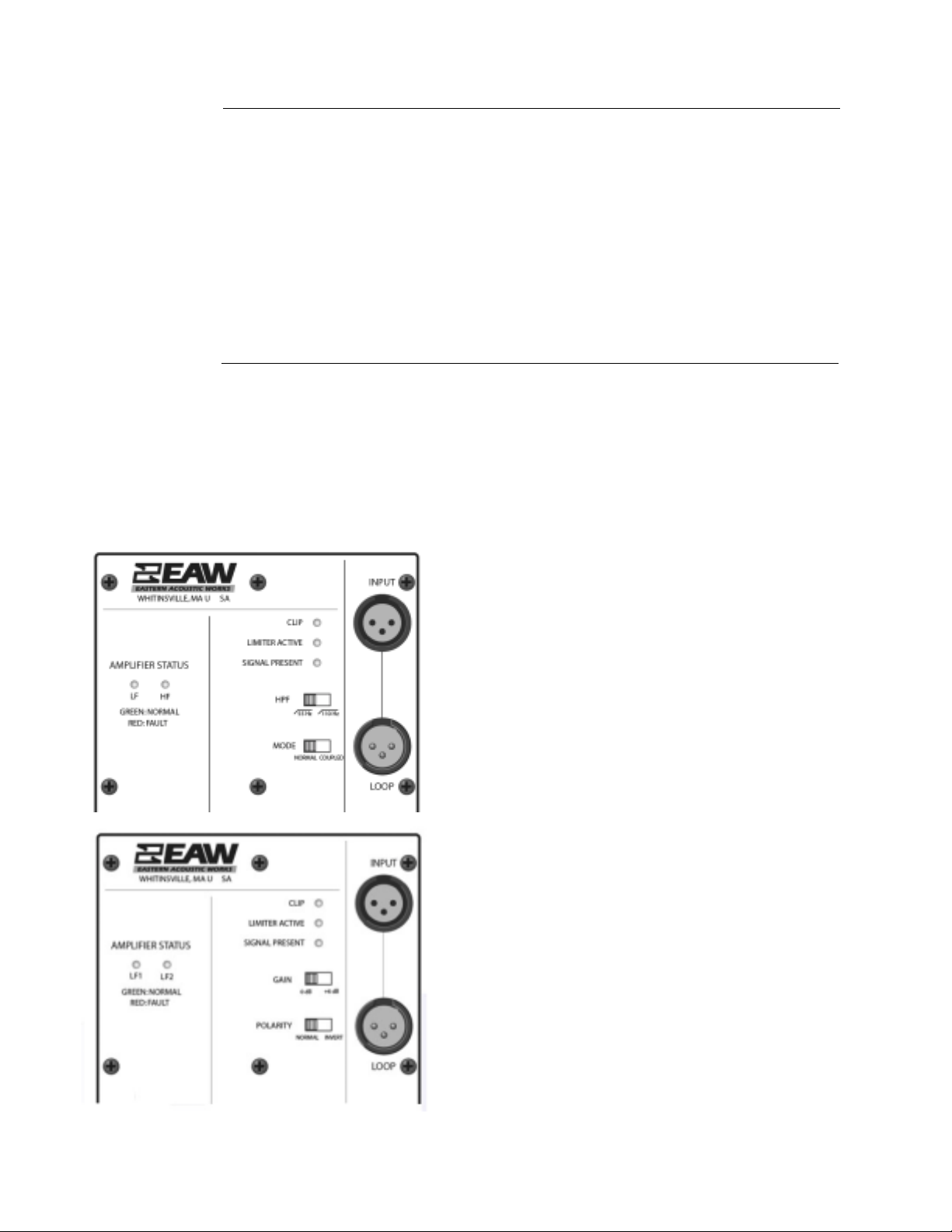
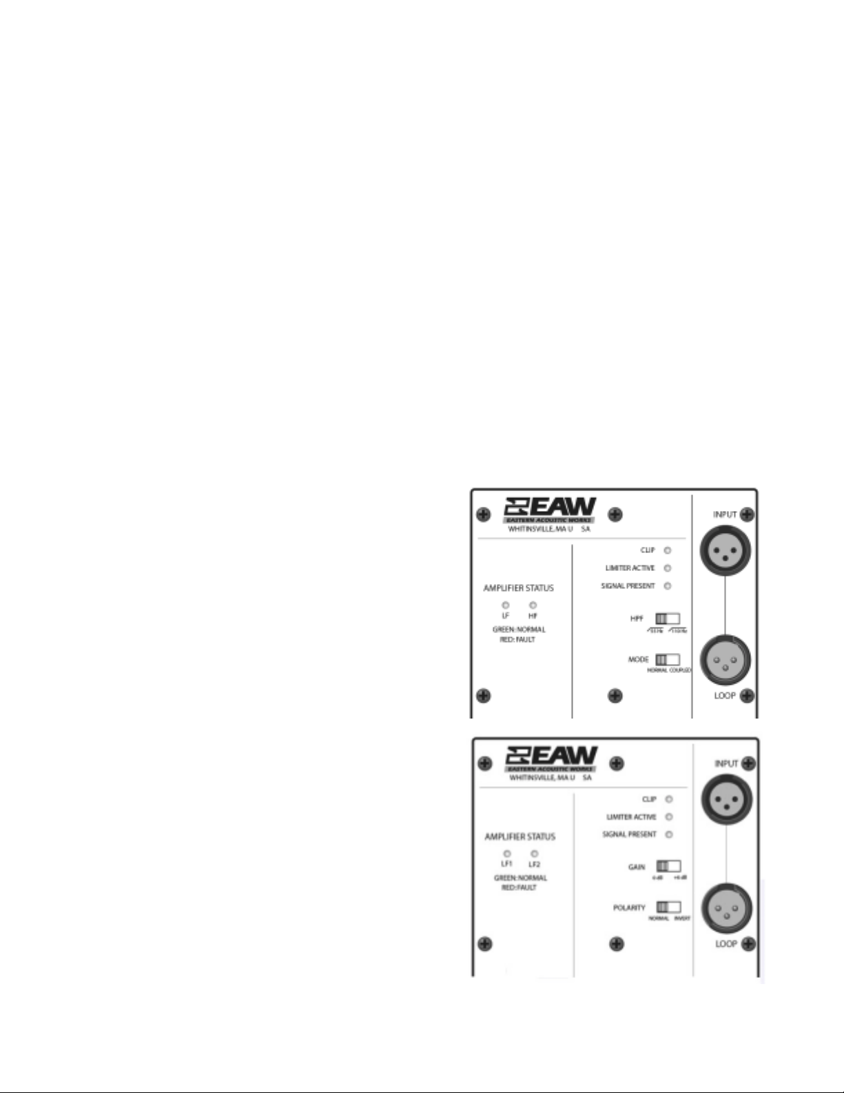
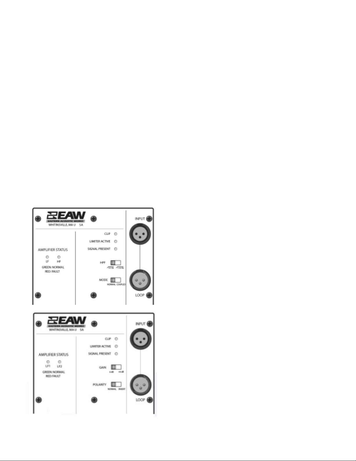
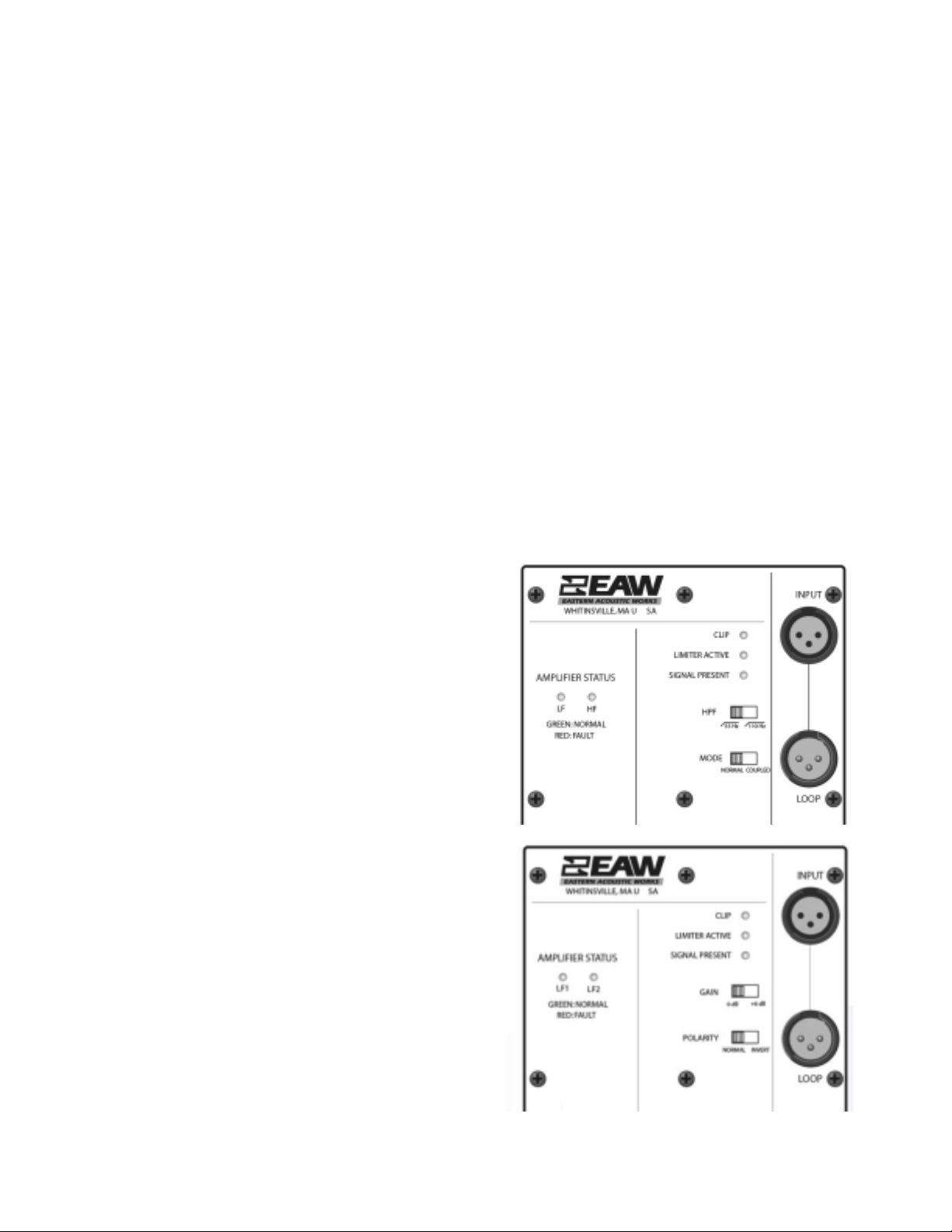
6.1.1 Input Panel
The audio input connection to the loudspeaker can be
made to either the female INPUT or male LOOP
connector on the rear of the loudspeaker. Normaly, the
female connector is used for the input signal. Connect
the output from your signal source (mixing console,
microphone preamp, or other line-level source) to either
XLR-3 connector. This is an electronically balanced input
designed to be connected to a balanced signal source.
Pin Connection
1 shield
2 signal plus or cold
3 signal minus or hot
6.1.2 Loop Connector
The Loop connector is hard-wired to the Input connector and thus carries the identical signal.
This connector is used to "daisy-chain"the input signal to multiple NT loudspeakers and NT
subwoofers. Because the signal processing, including the crossover, is built in, full-range
loudspeakers and subwoofers may be daisy-chained together from a single signal source.
NOTE: To avoid potential interference, do not leave an un-terminated cable attached to
either the Input or the Loop connector.
6.2 System GAIN
6.2.1 Level Control
The electronic sensitivity and gain in all full-range NT models is fixed by design. There are
no adjustable, input level controls. This means that whenever the loudspeaker is connected
to the ac mains and provided with audio signal the output level is always controlled
externally to the loudspeaker. This way, there is no question about a misadjusted level
control on the loudspeaker. This also largely prevents overdriving the equipment directly
upstream of the loudspeakers.
The sensitivity is designed to match with a wide range of professional line level audio
equipment with nominal operating levels of 0 dBu (= 0.775 V). Consumer equipment has
nominal operating levels of 8 dB to 10 dB below 0 dBu. If used with the latter equipment,
it may not be possible to reach full output before clipping upstream equipment. In such
cases, there are 3rd party devices available that can be inserted into the signal path to match
the impedance and level between consumer and professional equipment.
13
1
2
3
1
2
3
Page 18

6.3 AC MAINS Connection
This section details the requirements for the ac mains connection required by each NT
loudspeaker and subwoofer.
6.3.1 AC MAINS Supply
WARNING: Read all instruction and cautionary notes concerning electrical power in the
EAW Loudspeaker Manual.
DANGER: Ensure that the ac mains voltage matches the voltage rating listed on the
loudspeaker next to the AC Mains connector. DO NOT APPLY 230 V MAINS POWER IF THE
VOLTAGE RATING ON THE LOUDSPEAKER IS 115 V. IMMEDIATE AND CATASTROPHIC
DAMAGE TO THE LOUDSPEAKER WILL RESULT AND MAY CAUSE A FIRE HAZARD,
SERIOUS PERSONAL INJURY, OR DEATH.
Alimentation Secteur
ATTENTION: Lisez toutes ls instructions et notes de sécurité sur l'alimentation secteur, dans
le mode d'emploi de l'enceinte EAW.
DANGER: Vérifiez la tension secteur de l'enceinte, sérigraphiée à côté de l'embase secteur de
l'enceinte. NE PAS APPLIQUER UNE TENSION SECTEUR DE 230 V SI L'ENCEINTE EST DE
115 V. LES DOMMAGES À L'ENCEINTE SERAIENT IMMÉDIATS ET IRRÉVERSIBLES - DE
PLUS, CES DOMMAGES PEUVENT ÊTRE SOURCE D'INCENDIE, DE BLESSURES GRAVES
VOIRE FATALES.
Alimentazione AC
ATTENZIONE: Leggere tutte le istruzioni e le avvertene riguardanti l'alimentazione elettrica,
incluse nel Manuale EAW Loudspeaker.
PERICOLO: Assicurarsi che il voltaggio dell'alimentazione utilizzata nell'area in cui si
intende utilizzare il diffusore, corrisponda al voltaggio riportato nel pannello posterore del
diffusore, vicino alla connessione di alimentazione AC. NON UTILIZZARE UN
VOLTAGGIO DI 230 V SE NEL DIFFUSORE VIENE INDICATO UN VOLTAGGIO DI 115 V.
IL DANNO PER IL DIFFUSORE SAREBBE IMMEDIATO E MOLTO SERIO, E POTREBBE
CAUSARE INCENDI, DANNI FISICIALLE PERSONE E LA MORTE.
Fuente de alimentación
PRECAUCION: Lea todas las instrucciones y advertencias relativas a la corriente eléctrica
que aparecen en el manual de altavoces EAW.
PELIGRO: Asegúrese que el voltaje de la salida de corriente coincida co el que aparece
indicado en el propio altavoz al lado del conector de entrada de corriente. NO APLIQUE
UN VOLTAJE DE 230 V SI SU ALTAVOZ FUNCIONA CON UN VOLTAJE DE ENTRADA DE
115 V. EL NO CUMPLIR ESTO PUEDE DAR LUGAR A DAÑOS INMEDIATOS Y
CATASTROFICOS EN E ALTAVOZ, ASI COMO AL RIESGO DE INCENDIOS, DAÑOS
SERIOS O INCLUSO LA MUERTE.
14
AC MAINS
~100 - 120VAC /
50 - 60Hz /10A
Page 19

Netzstromversorgung
WARNUNG: Lesen Sie alle Anweisungen und Sicherheitshinweise bezüglich der
Netzspannung in der EAW Lautsprecher Bedienungsanleitung.
GEFAHR: Versichern Sie sch, dass die zur Verfügung stehende Netzspannung mit der auf der
Rückseite des Lautsprechers angegebenen Spannung übereinstimmt. SCHLIESSEN SIE
KEINE 230 V NETZSPANNUNG AN, WENN DER LAUTSPRECHER FÜR 115 V
KONFIGURIERT IST. SOFORTIGE, KATASTROPHALE SCHÄDENSIND DIE FOLGE. ES
BESTEHT DIE GEFAHR VON FEUER, VERLETZUNG ODER TOD.
Each NT model is manufactured for a particular nominal ac mains voltage, either 115 V or 230 V.
Provide the loudspeaker with
ac mains circuit capable of:
6.3.2 AC Mains Cable
The supplied Neutrik® PowerCon® NAC3FCA plug mates with the Neutrik PowerCon
NAC3MPA AC MAINS jack on the loudspeaker.
CAUTION: The supplied ac mains plug may not be appropriate for local ac mains
receptacles. If not, have a qualified electrician remove the existing ac mains plug and install
a plug appropriate for the ac mains supply receptacle. Follow all local codes for this wiring.
WARNING: Ensure that ac power supply has a properly grounded safety ground. Failure to
follow this warning could cause equipment damage, injury, or death.
Cordon secteur
Le cordon secteur fourni est équipé d'une fiche Neutrik® PowerCon® NAC3FCA adatée à
l'embase secteur Neutrik PowerCon NAC3MPA de l'enceinte.
ATTENTION : Il se peut que le format de la fiche secteur ne corresponde pas à celui de votre
situation géographique. Dans ce cas, faites appel à un électricien agréé pour qu'il remplace
la fche par une autre du bon format. Respectez les normes électriques de câblage locales.
ATTENTION: Assurez-vous que la ligne secteur dispose d'une terre. Le non-respect de cette
précaution peut entraîner des dommages aux équipements et des accidents aux ersonnes
pouvant être fatals.
Cavo d'alimentazione AC
Il cavo Neutrik® PowerCon® NAC3FCA fornito in dotazione è collegabile al connettore
Neutrik PowerCon NAC3MPA AC MAINS presente nel diffusore.
CAUTELA: Il connettore del cavo d'alimentazione AC fornto in dotazione potrebbe non
essere adeguato per le prese di corrente impiegate nell'area in cui il diffusore viene utilizzato.
In questo caso, contattare un elettricista qualificato per sostituire la presa di corrente con
una dotata di connessione adeguaa. Per il cablaggio, occorre seguire la codifica corretta
utilizzata nell'area d'utilizzo.
ATTENZIONE: Assicurarsi che la presa d'alimentazione sia correttamente collegata a terra. Il
mancato rispetto di tali avvertenze potrebbe causare danni all'apparechiatura, nonché
infortuni alle persone o la morte.
15
Full-range
Subwoofer
115 V Model
100 V to 120 V, 50 Hz to 60 Hz
10 A
230 V Model
220 V to 240 V, 50 Hz to 60 Hz
6.3 A10 A
6.3 A
Page 20

Cable de alimentación
El enchufe Neutrik® PowerCon® NAC3FCA incluido en el cable encaja en la toma de entrada
Neutrik PowerCon NAC3MPA AC MAINS del altavoz.
PRECAUCION: El enchufe que viene en el cablede alimentación incluido puede no encajar
en las salidas de corriente de su zona. Si ocurre esto, contacte con un electricista profesional
para que sustituya el enchufe problemático y lo cambie por uno adecuado para la salida de
corriente. Compruebe que s sigan todas las normativas de seguridad aplicables.
PRECAUCION: Asegúrese que la fuente de alimentación tenga una conexión a tierra
correcta. El no cumplir con esta advertencia puede dar lugar a daños en el equipo, en las
personas que lo manejen o inclso la muerte.
Netzkabel
Das mitgelieferte Kabel kann an der Seite mit dem Neutrik® PowerCon® NAC3FCA in die
PowerCon NAC3MPA Buchse auf der Rückseite des Lautsprechers gesteckt werden.
VORSICHT: Das mitgelieferte Netzkabel besitzt möglicherweise einen etzstecker, der nicht
in Ihre Steckdose passt. In diesem Fall können Sie sich von einem zugelassenen
Elektrobetrieb einen passenden Netzstecker unter Berücksichtigung der jeweils gültigen
Vorschriften montieren lassen.
WARNUNG: Stellen Sie sicher, dass er Schutzleiter der Netzsteckdose ein gute Verbindung
zur Erde hat. Nichtbeachtung dieses Hinweises kann zu Schäden am Equipment, zu
Verletzungen oder zum Tod führen.
Power Cable Color Coding:
NOTE: If an extension cord is used for the ac mains, use only a cord rated for at least 1800 VA.
6.3.3 Power On / Off
CAUTION: There is no power switch on the loudspeaker. When connected to the ac mains,
the loudspeaker will be energized and fully operational with the output level controlled by
the signal source feeding the loudspeaker.
Connect the supplied ac mains cord to the PowerCon jack on the rear of the loudspeaker.
The PowerCon system uses a locking connecter. To lock, twist 1/4 turn clockwise after fully
inserting it into the jack. Then, connect the other end of the cable to the ac mains supply
receptacle. This will energize the loudspeaker.
Power On Sequence:
When energized, the loudspeaker's electronics will initialize. The initialization sequence
will last between 1.5 and 2 seconds, during which time the amplifier outputs are muted. The
indications for normal initialization are:
1. The Clip, Limit,and Signal Presence LEDs will flash together.
2. The LEDs will then flash twice in the following sequence:
Clip, Limit, and Signal Presence.
3. The Clip, Limit, and Signal Presence LEDs will go off; the Amplifier Status LEDs will
come on, illuminated green.
16
Conductor
Ungrounded
Grounded or Neutral
Earth or Safety Ground
115 V Models
Black
White
Green
230 V Models
Brown
Blue
Green / Yellow Stripping
Page 21

If it is desired to completely power off (de-energize) the loudspeaker, a conveniently located ac mains
disconnect must be supplied or the power cable must be unplugged from the ac mains supply.
6.4 Operating Controls - Full Range Loudspeakers
For the instructions in this section, refer to the accompanying Figure.
These switches electronically configure the loudspeaker for use with and without a
subwoofer and for different mounting positions.
NOTE: The recommendations given are general guidelines and cannot address all
applications or loudspeaker configurations. Use measurements and listening tests to
determine the best setting for a particular situation.
6.4.1 Setting the HPF (High Pass Filter)
The HPF switch sets the low frequency roll-off frequency or the system. This means that,
below the roll-off frequency, the lower the frequency the more the attenuation is applied to
the input signal.
Recommended Use:
55 Hz (switch to left):
Without Subwoofer:
Provides normal low frequency response for
music or a combination of music and speech.
With Subwoofer:
Not recommended. This will cause excessive
energy between 55 Hz and 110 Hz.
110 Hz (switch to right):
With Subwoofer:
Provides normal acoustic integration with a
subwoofer.
Without a Subwoofer:
Recommended for speech only; not
recommended for music.
6.4.2 Setting the Operating Mode
The Mode switch sets the voicing of the loudspeaker for different applications. It
compensates for differences in performance caused by different mounting conditions with
a LF shelving filter in the coupled position. The filter reduces the LF output in the range of
frequencies affected by 1/2 space loading.
Recommended Usage:
Normal (switch to left):
Use when the loudspeaker is aimed at the audience, typically stacked on stage or
stand/pole mounted.
Coupled (switch to right):
Use when the loudspeaker is coupled to a surface such as the stage floor as a performer
monitor or when mounted on a wall or the ceiling.
Use when arrayed with other NT loudspeakers to attenuate excess energy caused by
mutual coupling.
Use when room acoustics are "live", meaning with higher reverberation times, to improve
intelligibility by reducing the amount of LF reverberant energy excited by the loudspeaker.
17
1
2
3
1
2
3
Page 22

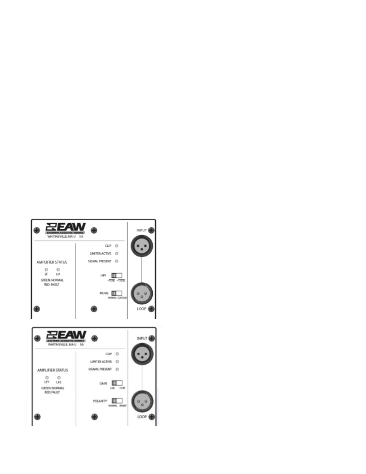
6.5 Operating Controls - Subwoofer
For the instructions in this section, refer to the
accompanying Figure.
These switches electronically configure the
subwoofer for use with a full-range
loudspeaker depending on the subwoofer's
positioning relative to the full-range
loudspeaker.
NOTE: The recommendations given are
general guidelines and cannot address all
applications or loudspeaker configurations.
Use measurements and listening tests to
determine the best setting for a particular
situation.
6.5.1 Setting the Gain Switch
The gain switch adjusts the input to 0 dB or +6 dB gain.
0 dB (switch to left)
Use for the common situation where the subwoofer is floor-mounted and the
full-range loudspeaker is pole or stand mounted above it.
+6 dB (switch to right)
Use when more subwoofer level is needed, such as when both the full-range and
subwoofer are suspended.
For situations where a wider range of gain control is needed, use either of these
recommended methods.
1. Provide a separate signal feeds to the full-range and subwoofer, each feed having its
own level control. This is normally accomplished using separate auxiliary or matrix
outputs on a mixing console
2. Provide an external attenuator to the loudspeaker that needs less gain. This can be
a fixed resistive attenuator, ideal for permanent installations. Where frequent
adjustment may be needed, such as in a portable system, an adjustable level control
may be inserted into the signal line to the loudspeaker needing less gain. A 20k ohm
to 40k ohm potentiometer with an audio or log taper can provide the desired results.
6.5.2 Setting the Polarity
Recommended usage:
Normal (switch to left)
Use to provide normal integration with a full range loudspeaker that is either stacked
on top of or pole mounted to the subwoofer.
Invert (switch to right)
Use when the sound of the subwoofer and full-range loudspeaker do not integrate well,
meaning there is bass loss in the listening area. This is usually caused when the subwoofer
is located at a different distance to the listeners than the full-range loudspeaker or
because of destructive room reflections. Given the unpredictability of low frequency
response in a room, the Polarity setting may or may not improve the results. In some
cases, there may be a difference in the results, but not a better or worse result.
18
Page 23

Section 7 Operation
7.1 Operating Limits
7.1.1 Operator Responsibility
It is the responsibility of the audio system operator to operate the loudspeaker within its
capabilities. This is the only way to ensure that the loudspeaker is not stressed beyond its
limits to the point of damage or failure. Refer to the EAW Loudspeaker Manual for detailed
Operating instructions and suggestions. NT's LED status indicators will show when the
loudspeaker is operating at or beyond its maximum capabilities.
7.2 Adjusting the Output Level
With a source program playing, gradually turn up the level of your signal source until the desired
volume is reached or until the CLIP light flashes only occasionally, whichever comes first.
7.3 Operating Indicators
For the instructions in this section, refer to the
accompanying Figures.
7.3.1 Limiter Active
The limiting parameters set in NT's DSP are
engineered to provide a high level of protection for
the transducers while maximizing sonic
performance and output. A Limiter Active indicator
in the rear input panel illuminates when limiting is
occurring. If this is flashing occasionally, meaning
no more than once every 3 seconds or so, then
levels are probably OK, but at maximum. If this
indicator is flashing more than once every 3
seconds or so, reduce the input signal level.
7.3.2 Clip
A Clip indicator on the rear panel illuminates if any
of NT's electronics are being driven into clipping.
This includes the entire signal chain from the input
stage through the DSP. Clipped signals can more
easily damage transducers as they can raise the
average signal level significantly with a spectrum
that differs significantly from the input signal.
7.3.3 IMPORTANT: Operator Response
If either or both of the Limiter Active and Clip indicators are flashing occasionally, meaning
no more than once every 3 seconds or so, then the signal level may not be excessive.
However, this is a CLEAR indication the loudspeaker is being operated near or at its
maximum limits. If either or both of these indicators are flashing more than once every 3
seconds or so, or are on steadily, reduce the input signal level or damage to the drivers is
likely to occur.
CAUTION: Electronic limiters cannot provide absolute protection against driver failure.
Thus, if limiting is occurring, it is a warning that excessive signal levels are being
approached. It is NOT an indication that the loudspeaker is successfully protecting itself.
19
Page 24

7.3.4 Amplifier Status
An Amplifier Status indicator monitors the status of each of the two amplifiers in the fullrange and subwoofer models. If illuminated Green, the amplifier status is Normal. If
illuminated Red, a protection circuit has activated and the amplifier is in Fault status.
The causes for a Fault indication can be:
• Amplifier overheating
• Power supply overheating
• Excessive amplifier output current
• Excessive power supply current
• Low ac mains voltage
• Low amplifier output voltage
• Electronic failure
To minimize audio downtime or operation at reduced levels, the protection circuits will
automatically reset after the fault condition is lowered to an acceptable level or removed.
The only exception is protective shut-down due to electronic failure.
7.3.5 Signal Present
The Signal Present indicator illuminates when an audio signal greater than 30 dBu (25 mV)
is present at the input connector.
7.4 Signal Processing
7.4.1 Internal Signal Processing
The NT Series incorporates sophisticated, digital signal processing to optimize performance
and reliability. Normally, no external signal processing is required. The internal processing
will provide excellent results in a variety of venues. The processing was determined from
extensive laboratory measurements and field testing to provide the maximum performance
in terms of frequency response, phase response, power handling, and audio quality. It affects
many aspects of the loudspeaker's performance including frequency response, beamwidth
consistency, output level capability, and wavefront coherency.
7.4.2 External Signal Processing
In some applications, external signal processing may be used because of room acoustics,
audio program content, or personal taste. In such cases, use standard analog or digital
equalizers. Avoid radical settings as these can alter the performance in adverse ways not
readily apparent, such as reducing power handling or altering the beamwidth.
7.4.3 Limiters
NT loudspeakers have built-in, factory set limiting. The limiter characteristics and settings
were determined to provide the maximum protection possible, to minimize the sonic effects,
and to integrate closely with the amplifier capabilities. Defeating such limiting by using an
external limiter could expose the drivers or amplifiers to operation beyond their limits.
External limiting should only be used to limit the maximum output to some level below that
allowed by the factory limiting. In this case, choose limiter settings that minimize the sonic
effects when the limiting is active.
20
Page 25

Section 8 Maintenance and Service
8.1 Maintenance
Your EAW loudspeaker may require little to no regular attention for normal use. However,
performing regular inspections and maintenance can ensure your loudspeaker remains in
optimum operating and cosmetic condition. Refer to the EAW Loudspeaker Manual for
periodic inspection and maintenance recommendations and procedures.
8.2 General Service
CAUTION: THESE SERVICING INSTRUCTIONS ARE FOR USE BY QUALIFIED SERVICE
PERSONNEL ONLY. TO REDUCE THE RISK OF ELECTRIC SHOCK DO NOT PERFORM
ANY SERVICING OTHER THAN THAT CONTAINED IN THE OPERATING
INSTRUCTIONS UNLESS YOU ARE QUALIFIED TO DO SO.
WARNING:
Disconnect the ac mains cable before performing any servicing.
Entretien Général
ATTENTION: Déconnectez le cordon secteur avant tout entretien.
Assistenza Tecnica
ATTENZIONE: Disconnettere l'alimentzione AC prima di effettuare qualsiasi intervento tecnico.
Mantenimiento General
PRECAUCION: Desconecte el cable de alimentación antes de realizar ningún tipo de
mantenimiento o reparación.
Service
WARNUNG: Ziehen Sie das Netzkabel aus der Steckdose, evor an der Box gearbeitet wird.
Certain NT loudspeaker components are field replaceable. These include the drivers and
amplifier module. All other service and repair information must be obtained by contacting
the EAW Service Department or the service department of the EAW Distributor for your
country. See the EAW Loudspeaker Manual for contact information. This applies to both
warranty and non-warranty faults.
8.2.1 AC Mains Fuse
CAUTION: To maintain safety approval certifications, use a fuse that meets the specific time
delay, pulse current capability/melting integral (I2t / A2s), and breaking capability listed.
DANGER: Note and be sure to replace the fuse in the same physical orientation as when it
was removed. Double check the circuit board labeling to ensure the orientation is correct for
the proper ac mains input voltage. Failure to follow this warning could result in the incorrect
voltage being applied to the loudspeaker. IF 230 V IS APPLIED TO A 115 V LOUDSPEAKER,
IMMEDIATE AND CATASTROPHIC DAMAGE TO THE LOUDSPEAKER WILL RESULT AND
MAY CAUSE A FIRE HAZARD, SERIOUS PERSONAL INJURY, OR DEATH.
21
Page 26

Fuse Type:
115 V models
T10A H 125 V: I2t >= 180 A2s, T = time lag (slo-blow), H = high-breaking (1500 A)
Vendor: Wickmann, part #181 2100 002 (= qty 10)
230V models
T6.3A H 125 V, I2t >= 110 A2s, T = time lag (slo-blow), H = high-breaking (1500 A)
Vendor: Wickmann, part #181 1630 002 (= qty 10)
Fusible secteur
ATTENTION: Pour que l'enceinte respecte les normes de sécurité imposées, utilisez un
fusible ofrant les mêmes caractéristiques de temporisation, de capacité en courant/fusion
(I2t/A2s), et de capacité de rupture que celles données.
DANGER: Notez l'orientation du fusible lors de son retrait et respectez cette orientation lors
du montage du nouveaufusible. Vérifiez à nouveau les indications sur le circuit imprimé
pour garantir l'orientation correcte en fonction de la tension secteur. Le non- respect de ces
instructions peut entraîner l'application d'une mauvaise tension secteur à l'enceinte. SI VOU
APPLIQUEZ UNE TENSION SECTEUR DE 230 V À UNE ENCEINTE DE 115 V, LES
DOMMAGES À L'ENCEINTE SERONT IMMÉDIATS ET IRRÉVERSIBLES - DE PLUS, CES
DOMMAGES PEUVENT ÊTRE SOURCE D'INCENDIE, DE BLESSURES GRAVES VOIRE
FATALES
Type de fusible :
Modèles en 115 Vca
T10A H 125 V : I2t >= 180 A2s, T = temporisation (fusion lente), H = haute rupture
(1500 A)
Revendeur : Wickmann, pièce référence 181 2100 002 (= par 10)
Modèles en 230 Vca
T6.3A H 125 V, I2t >= 110 A2s, T = temporisation (fusion lente), H = haute rupture
(1500 A)
Revendeur : Wickmann, pièce référence 181 1630 002 (= par 10)
Fusibile AC
CAUTELA: Per essere conformi alle certificazioni di sicurezza approvate, utilizzare fusibili
che soddisfino le specifiche relative ai tempi di ritardo, alla capacità d'ipulso di
corrente/fusione integrale (I2t / A2s) e il potere d'interruzione riportati.
PERICOLO: Assicurarsi di sostituire il fusibile inserendolo nella medesima posizione del
fusibile originale. Controlla attentamente le indicazioni del circuito stampato assicurandoti
che la posizione sia corretta per il voltaggio dell'alimentazione AC. In caso contrario, si
rischia che un voltaggio non corretto venga applicato al diffusore. APPLICANDO UN
VOLTAGGIO DI 230 V AD UN DIFFUSORE DA 115 V, IL DANNO PER IL DIFFUORE
SAREBBE IMMEDIATO E MOLTO SERIO, E POTREBBE CAUSARE INCENDI, DANNI FISICI
ALLE PERSONE E LA MORTE.
Tipo di fusibile:
Modelli a 115 V
T10A H 125 V: I2t >= 180 A2s, T = Time Lag (Slo-Blow), H = High-Breaking (1500 A)
Prodotto da: Wickmann, parte #181 100 002 (= qtà 10)
Modelli a 230 V
T6.3A H 125 V, I2t >= 110 A2s, T = Time Lag (slo-blow), H = High-Breaking (1500 A)
Prodotto da: Wickmann, parte #181 1630 002 (= qtà 10)
22
Page 27

Fusible de corriente
ATENCION: Para mantener los niveles de seguridad adecuado, use un fusible que cumpla
con los valores específicos de tiempo de retardo, capacidad de corriente de pulsos / integral
de corriente (I2t / A2s) y punto de ruptura que aparezcan indicados.
PELIGRO: Asegúrese de sustituir el fusible colocando el de recabio en la misma orientación
física que el original. Compruebe la indicación de la placa de circuitos para asegurarse de
que la orientación sea la correcta para el voltaje de entrada que corresponda. El no cumplir
con esta advertencia puede hacer que se apicado un voltaje de entrada incorrecto al altavoz.
EL APLICAR UN VOLTAJE DE 230 V A UN ALTAVOZ QUE FUNCIONE CON UN VOLTAJE
DE ENTRADA DE 115 V PUEDE DAR LUGAR A DAÑOS INMEDIATOS Y CATASTROFICOS
EN EL ALTAVOZ, ASI COMO AL RIESGO DE INCENDIOS, DAÑOS SERIOS OINCLUSO LA
MUERTE.
Tipos de fusible:
modelos de 115 V
T10A H 125 V: I2t >= 180 A2s, T = retardo (ruptura lenta), H = corriente elevada
(1500 A)
Distribuidor: Wickmann, nº referencia 181 2100 002 (cantidad mínima 10)
modelos de 230 V
T6.3A H 125 V, I2t > 110 A2s, T = retardo (ruptura lenta), H = corriente elevada
(1500 A)
Distribuidor: Wickmann, nº referencia 181 1630 002 (cantidad mínima 10)
Netzsicherung
VORSICHT: Um die Sicherheitsbestimmungen zu erfüllen, verwenden Sie ausschließlich
Sicherungen ie die korrekte Charakteristik, Spitzenstrombelastbarkeit und Auslösezeit (I2t /
A2s) sowie Auslösestrom besitzen.
GEFAHR: Beachten Sie, dass die Sicherung in der gleichen Position eingesetzt wird, wie sie
herausgenommen wurde. Überprüfen Sie abschließen, ob der Sicherungseinsatz so
eingesetzt wurde, dass die korrekte Netzspannung eingestellt ist. Durch fehlerhaften Einbau
gelangt die falsche Netzspannung zum Lautsprecher. SCHLIESSEN SIE KEINE 230 V
NETZSPANNUNG AN, WENN DER LAUTSPRECHER FÜR 115 V KONFIGRIERT IST.
SOFORTIGE, KATASTROPHALE SCHÄDEN SIND DIE FOLGE. ES BESTEHT DIE GEFAHR
VON FEUER, VERLETZUNG ODER TOD.
Sicherungstyp:
115 V Modelle
T10A H 125 V: I2t >= 180 A2s, T = Zeitcharakteristik (Träge), H =
Auslösespitzenstrom (1500 A), Anbieter: Wickmann, Teilenummer: 181 2100 002
(= VPE 10)
230 V Modelle
T6.3A H 125 V, I2t >= 110 A2s, T = Zeitcharakteristik (Träge), H =
Auslösespitzenstrom (1500 A), Anbieter: Wicmann, Teilenummer 181 1630 002
(= VPE 10)
23
Page 28

If excessive ac mains input current is detected, an internal fuse will blow. This can occur for
a variety of reasons, such as internal failure, excessive ac mains voltage, or excessive
amplifier output levels. If the fuse blows, have a technician replace it with the identical type
of fuse.
In the unlikely event the fuse blows again, internal failure is indicated, requiring
troubleshooting and repair by a qualified service technician. Do not attempt further use of
the loudspeaker until such repairs are made.
8.3 Field Troubleshooting
See the EAW Loudspeaker Manual for field troubleshooting procedures.
8.4 Driver Service
For the instructions in this section, refer to the accompanying Figures.
Full-Range
The drivers can be field serviced by replacing the entire driver or having the driver repaired
(such as diaphragm replacement) by a qualified service technician.
1. Access the drivers by removing the front grille.
2. Remove the LF driver or HF horn/driver
assembly by unscrewing their retaining screws.
3. Lift the LF driver or HF horn/driver assembly
from the baffle.
4. Disconnect the signal cable from the driver
(not shown).
To reinstall or replace the component, reverse the
above steps.
IMPORTANT: When reconnecting the signal wires
to the transducer, connect the colored wire to the
plus (+) terminal and the black wire to the (-)
minus terminal.
Subwoofer
The drivers can be field serviced by replacing the entire driver or having the driver repaired
(such as diaphragm replacement) by a qualified service technician.
1. Access the drivers by removing the front grille.
2. Remove the LF driver(s) by unscrewing their
retaining screws.
3. Lift the driver(s) from the baffle.
4. Disconnect the signal cable from the driver.
To reinstall or replace the driver, reverse the above
steps. Make sure the reversed transducer is installed
reversed and is connected with the blue and black
signal wires.
IMPORTANT: When reconnecting the signal wires to
the transducer, connect the colored wire to the plus (+)
terminal and the black wire to the (-) minus terminal.
24
Page 29

25
8.5 Amplifier Service
WARNING: Disconnect the ac mains cable before doing this procedure.
ATTENTION: Déconnectez le cordon du secteur avant d'entamer cette procédure.
ATTENZIONE: Prima di procedere con questa operazione, disconnettere il cavo
d'alimentazione AC.
PRECAUCION: Desconecte el cable de alimentación antes de realizar este proceso.
WARNUNG: Ziehen Sie den Netzstecker aus der Steckdose, bevor Sie mit dieser Prozedur beginnen.
Faulty electronics are serviced by replacing the entire amplifier module.
8.5.1 Amplifier Modules
There are two types of NT amplifier modules:
one for the NT full-range models and one for the subwoofer.
1. Full-range: Input, DSP, 1000 W @ 4 ohm LF amplifier, 500 W @ 4 ohm
HF amplifier, and power supply.
2. Subwoofer: Input, DSP, two 1000 W @ 4 ohm amplifiers, and power supply.
For the NT full-range models (NT2x & NT5x), each amplifier module has the DSP settings
for all models stored in on-board memory. The active settings are determined by on-board
dip switch settings. Thus,amplifier modules for the full-range models are interchangeable
by simply resetting the dip switches for that particular model.
8.5.2 NT Amplifier Replacement Modules and Dip Switch Settings
An amplifier replacement module consists of the power amplifiers, DSP board, power
supply, connectors, and indicators; all pre-mounted on the amplifier panel.
Amplifier Module Replacement Part Numbers & Dip Switch Settings
NOTE: If the incorrect DIP switch position is used, poor/incorrect performance will result,
at best sounding bad, at worst causing equipment failure.
8.5.3 Replacing the Amplifier Module
1. Remove the amplifier module from the other side of the enclosure by removing its12
retaining screws.
2. Disconnect the quick release connector for the transducer cabling.
3. Configure the replacement amplifier for the NT model by setting the dip switch. See
the chart in Section 8.5.2 for the correct settings. The dip switch is located behind the
input receptacles on the backside of the amplifier module.
4. Once the dip switch is programmed, connect the transducer cabling to the
replacement module.
NT Model # 115 V Module
NT26
NT29
NT56
NT59
NTS22
#0016088
#0016088
#0016088
#0016088
#0016090
230 V Module
#0016584
#0016584
#0016584
#0016584
#0016585
Dip Switch Settings
123
Off
Off
Off
Off
Off
Off
Off
Off
Off
On
NOTE: Off is up, On is down.
Off
Off
On
On
Off
4
Off
On
Off
On
Off
Page 30
26
5. Install and refasten the amplifier panel, securely
tightening all screws.
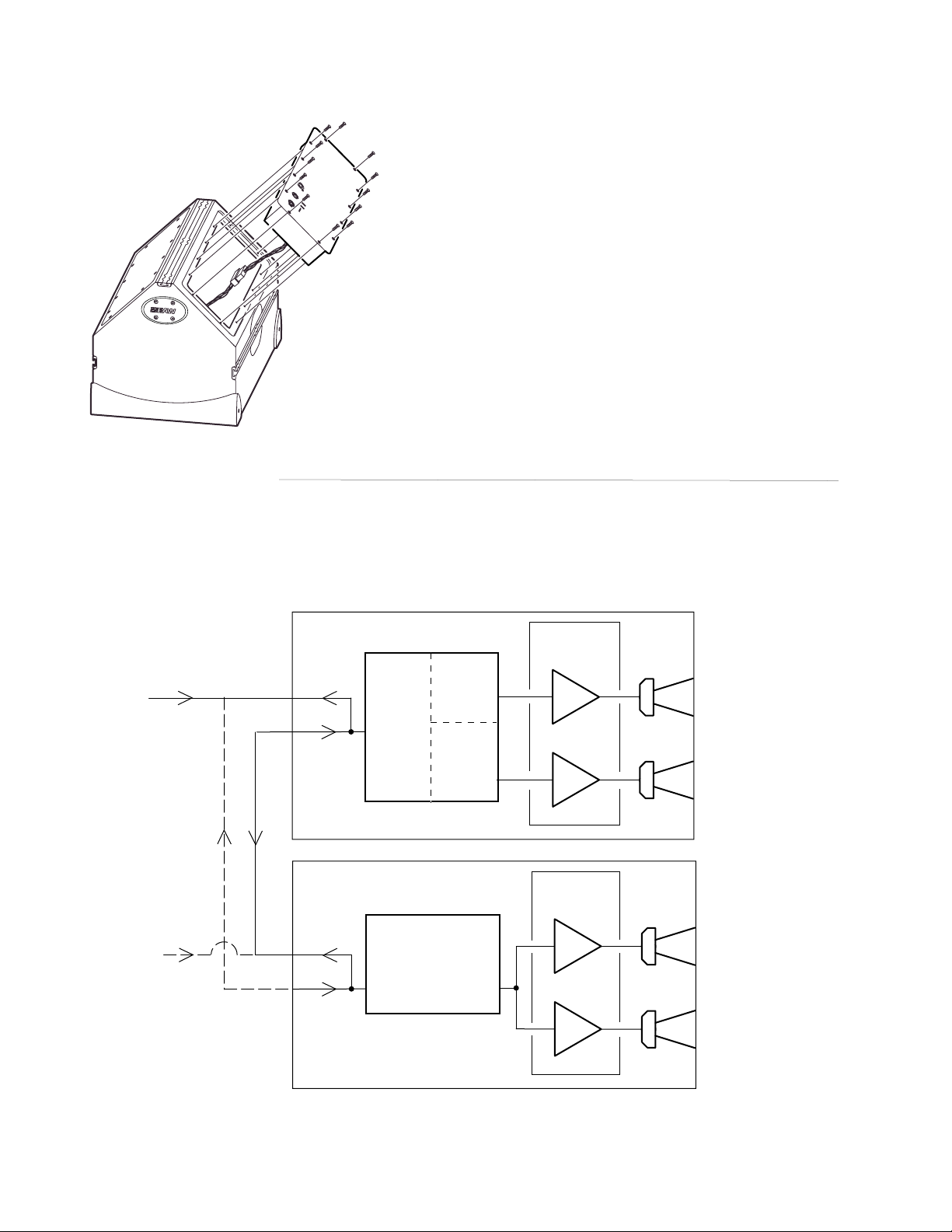
Section 9 Block Diagram
This is a block diagram of an NT Full-Range with an NT subwoofer. A full-range
input signal is connected to the full-range loudspeaker and looped through to the
subwoofer (solid lines). Alternately, the full-range input can be connected to the
subwoofer and looped through to the full-range loudspeaker (dotted lines).
FULL-RANGE
INPUT SIGNAL
(FULL-RANGE
INPUT SIGNAL)
THRU
IN
NT FULL-RANGE
THRU
IN
NT SUBWOOFER
DSP PC
BOARD
INPUT A/D
DSP PC
BOARD
INPUT A/D
HPF
EQ
LIMIT
DELAY
LPF
EQ
LIMIT
DELAY
EQ
DELAY
LPF
LIMIT
D/A
D/A
D/A
AMPLIFIER &
POWER SUPPLY
ASS'Y
AMP
500 W @ 4 OHM
AMP
1000 W @ 4 OHM
AMPLIFIER &
POWER SUPPLY
ASS'Y
AMP
1000 W @ 4 OHM
AMP
1000 W @ 4 OHM
HF
LF
LF
LF
Page 31

27
Page 32

One Main Street, Whitinsville, MA 01588 tel: 800 992 5013 / 508 234 6158 fax: 508 234 8251 web: www.eaw.com
The Laws of Physics | The Art of Listening
EAW is the worldwide technological and market leader in the design and manufacture of high-performance professional loudspeaker systems.
RD0385 (D) JAN06
 Loading...