

Page 1
M
R
A
N
O
F
C
R
E
E
P
L
A
C
I
T
S
U
O
C
A
PRELIMINARY PRODUCT INFORMATION
P
A
R
T
N
E
R
S
H
I
P
Technical Specifications MX8000
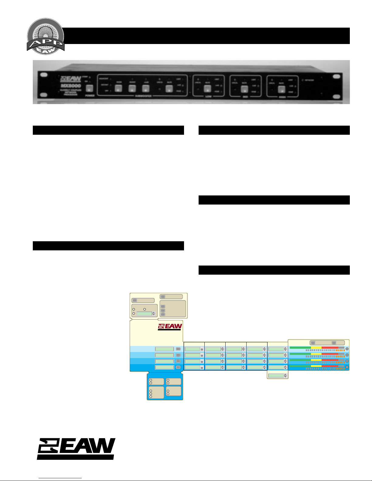
MX8000 Close Coupled Network Processor
CLOSER COUPLING OF ACTIVE ELECTRONICS
The concept of Close Coupling™ developed by EAW Executive Vice President,
Engineering Kenton G. Forsythe is unique. EAW engineers integrate active
signal processing into the total loudspeaker system – which may often
include internal passive electrical networks and even acoustical filters that
operate simultaneously with the external processor – in order to optimize the
system’s acoustic transfer function. EAW processors do not rely on dynamic
effects to disguise limitations in the electromechanical and acoustical aspects
of the system. Therefore they do not change the loudspeaker’s tonal balance
or power response at high output levels.
The MX8000 maintains this approach, which has been proven on concert
tours and installations worldwide. It includes all the functions of previous
MX Series CCEP™ units, and adds new dimensions of signal processing
power and a new, more powerful interface that gives the system designer
and operator more information, control and flexibility. EAW engineers will
be able to acheive even better acoustic performance by integrating these
new capabilities into existing EAW loudspeaker systems as well as new
systems under development.
HYBRID ANALOG/DIGITAL TECHNOLOGY
Live sound reinforcement demands the highest available dyanmic range
and signal-to-noise performance. In order to achieve the highest possible
dynamic range, the MX8000 design team has opted to implement most
signal processing functions in the analog domain. The MX8000’s analog
functions include:
• A four-way crossover using asymmetrical
fourth-order filters
• RMS limiting on each frequency band to
protect drivers against thermal failure
• Peak limiting on each band to prevent
amplifier clipping
• Six bands of parametric equalization
provide for flexible system optimization
• Subwoofer cone excursion limiting
• Phase compensation for coherent
acoustic summing at crossover points
• Subwoofer OFF (three-way), ADJacent
(true four-way) and DIStant (three-way
plus subwoofer) modes.
Digital technology has been used wherever
it would not compromise the audio signal
path. Thus all of the above functions are controlled
digitally via the front panel or the two types of remote
control interface. In addition, the MX8000 includes:
• Digital delay lines on each frequency band
• Minimum delay resolution of 5.208 microseconds
allows drivers or adjacent loudspeaker systems to be time aligned
within fractions of an inch
• Maximum delay time of 341 milliseconds per band allows control of
arrival times over a wide range.
• Provide coherent signal arrival time from multiple speaker systems.
UNIT CONTROLS
POWER
AMPLIFIER GAIN
+ 32
+ 26
Unit Controls
Calibration
Gain Set
RMS Set
Peak Limit Set
Signal Delay
Metering
Subwoofer Controls
HIGH FREQUENCY
MID FREQUENCY
LOW FREQUENCY
SUBWOOFER
PANEL LOCK
SAVE/RECALL SETTING
SAVE TO MX8000
SAVE TO DISC
RECALL
MX8000
Close Coupled
Network Processor
NAME MUTE
SUBWOOFER CONTROLS
+ 0 dB
NORMAL
+ 6 dB
SUB MODE
180°
SOURCE
ADJ
MAIN
DIST
DIRECT
OFF
TWO REMOTE CONTROL OPTIONS
The MX8000 extends the emerging audio control network to the loudspeaker system. Close Coupled signal processing functions as well as
output gain and other setup parameters can be controlled via the front
and rear panels, or remotely from any personal computer. The first remote
control option is an RS232 serial port. The second is a proprietary
implementation of the MediaLink network interface. The remote control
is the only user access to the digital delay settings, the individual band
gain settings and the limiter settings. This system allows a systems
engineer centralized control of multiple loudspeaker arrays.
A UNIQUELY POWERFUL MEDIALINK INTERFACE
Previous MediaLink implementations have used Lone Wolf Corporation’s
MediaLink chip for all communications and control functions. In the
MX8000, the same standard MediaLink chip handles network communications and housekeeping chores, while a second internal microprocessor translates the network messages into control vectors for the MX8000’s
parameter settings. The internal microprocessor also relays system and
operating status messages to the network chip. This gives the MX8000
much greater flexibility as well as signficantly enhanced data throughput
capacity.
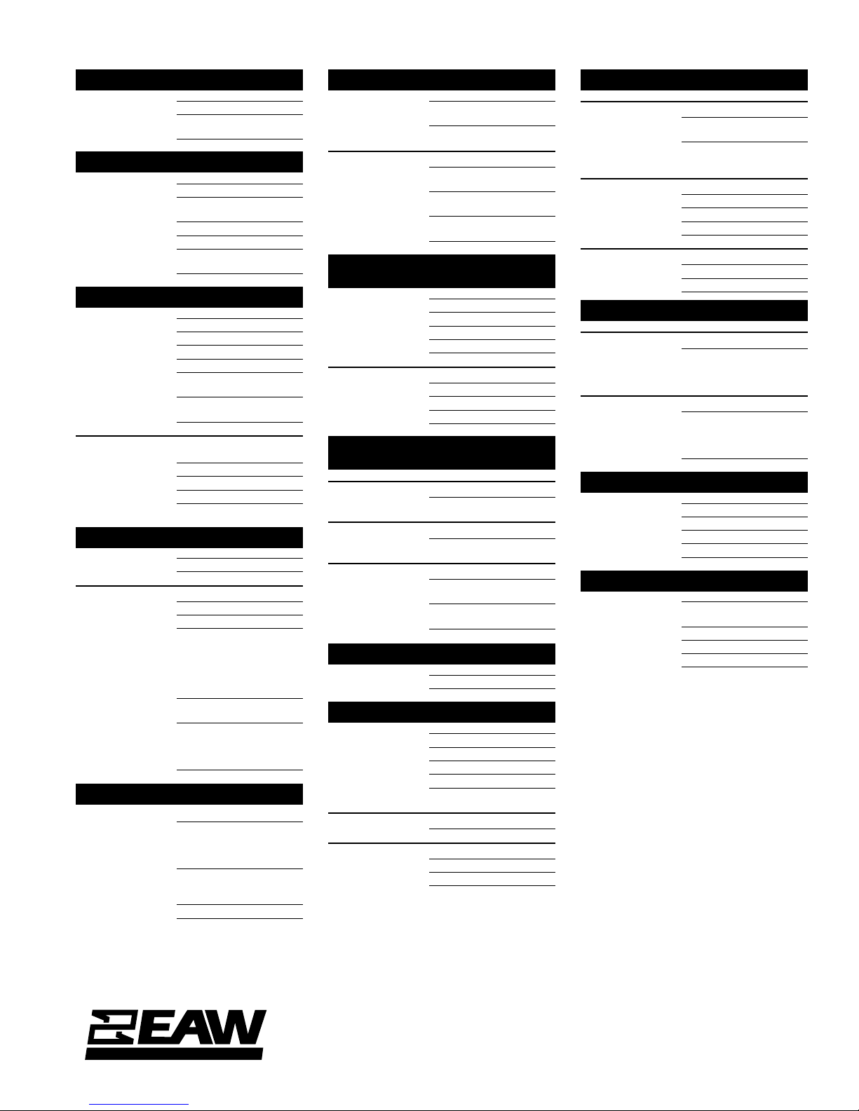
AN ADVANCED GRAPHIC USER INTERFACE
The prerelease version of the MX8000’s graphic user interface is shown
below. The control surface can be collapsed or expanded by the user
depending on the needs of the particular application. Password protection will allow any level of access from zero (remote and front panel
controls disabled) to full adjustment of all remote addressable MX8000
parameters. Thus the interface accomodates the requirements of every
user from the minimally competent operator to the expert sound system
designer. EAW is developing this interface and the accompanying screens
as a prototype of the virtual control surface of the future.
CALIBRATION GAIN SET RMS LIMIT SET PEAK LIMIT SET SIGNAL DELAY
UNC
UNC
UNC
UNC
ADDED DELAY
METERING
RMS LIMITING
RMS LIMITING
RMS LIMITING
RMS LIMITING
SHOW PEAKS RESET
EASTERN ACOUSTIC WORKS
One Main Street, Whitinsville, MA 01588 • (508) 234 - 6158 • FAX (508) 234 - 8251 • BBS (800) 889-2540
EAW products are continually improved. All specifications are therefore subject to change without notice. • PUB# MX8000/11/4/94 • Printed In USA
Page 2
MX8000 PRELIMINARY PRODUCT INFORMATION
AUDIO PERFORMANCE
Dynamic Range 105 dB
THD+N (0 dBu
20 Hz -20 kHz) 0.03% (≤0.08%)
INPUT
Connectors Female XLR (Locking)
Type Electronically Balanced
Differential
Differential 20 kΩ Input Impedance
Common-Mode 10 kΩ Input Impedance
Input Overload
20 Hz -20 kHz 21.8 dBu
OUTPUT
Connectors Male XLR (Locking)
Type Single-Ended
Impedance 10 Ω
Max Voltage +21.2 dBu
Minimum
Resistive Load 200 Ω
Maximum 22 nF (Outputs are stable
Capacitive Load with any capacitive load.)
Offset Voltage ±1.5 mV (±10 mV limit)
Output Noise (20 Hz -20 kHz, Rs = 600 Ω,
Amp Gain = 32 dB, All Bands Unity Gain)
SUB, LF -97.5 dBu (<-96.5 dBu)
MF -96.0 dBu (<-95.0 dBu)
HF -90.0 dBu (<-89.0 dBu)
ELECTRICAL/ENVIRONMENTAL
Dimensions 19” W x 1.75” H x 12.2” D
Line Input Power 55 Watts
Line Voltage Requirements
110 VAC Setting 90-135 VAC, 50-60 Hz
220 VAC Setting 195-270 VAC, 50-60 Hz
Line Input/
Fuse Holder IEC 320 block with
5x20 mm Fuseholder,
Line Voltage Selector
and Line Cord Socket,
UL/CSA/VDE
Operating
Temperature 0 - 50° Celsius
Accessories
Included UL/CSA Line Cord
Spare Line Fuse
(in fuseholder)
DIGITAL CONTROL OPTIONS
Observe/Control Signal Delay, Gain,
Threshold Settings, Mute
Status, Subwoofer Mode
Status, Power Status
Observe Only Level Metering, Calibra-
tion Status, Amp Gain
Status, Limiter Status
Current Platforms RS232, MediaLink
CROSSOVER FILTER TYPE
HF,MF High Pass 4th Order Linkwitz-Riley,
MF,LF, SUB Low Pass 4th Order Linkwitz-Riley,
LF Highpass Modes
Technical Specifications MX8000
Variable F
Variable F
ADJacent 4th Order Linkwitz-Riley,
Variable F
DISTant 2nd Order,Variable Q,
Variable F
SUB OFF 2nd Order, Variable Q,
Variable F
0
0
0
0
0
CROSSOVER CUTOFF
FREQUENCIES
HF High Pass 800 Hz - 10 kHz
MF Low Pass 800 Hz - 10 kHz
MF High Pass 80 Hz - 1 kHz
LF Low Pass 80 Hz - 1 kHz
SUB Low Pass 50 Hz - 800 Hz
LF Highpass Modes
ADJacent 50 Hz - 800 Hz
DISTant 12.5 Hz - 225 Hz
SUB OFF 12.5 Hz - 225 Hz
SYSTEM HIGHPASS
AND LOWPASS
Subwoofer High Pass
All Modes 2nd Order Butterworth,
Fixed LF High Pass
All Modes 2nd Order Butterworth,
Fixed System Low Pass
Variable F
-3 dB @ 25 Hz
#1 2nd Order Butterworth
-3 dB @ 44 kHz
#2 5th Order Chebishev
-3 dB @ 25 kHz
0
PASS BAND GAIN
HF/MF/LF/SUB -9 dB to +19 dB
DELAY
Time Base 12.288 MHz ±10 ppm
Maximum Delay 341.3 ms
Minimum Delay 5.2 µs
Delay Resolution 5.2 µs, 0.054 in.
Freq. Response 20 Hz – 15 kHz ±0.25 dB
THD+N @ Max Input Level
20 Hz – 20 kHz 0.006% (<0.01%)
Delay Type
Electrical Digital, 1 input, 4 output
Mechanical Plug-in Module
15 kHz – 20 kHz ±0.5 dB
LIMITER FUNCTIONS
Limiter Type
Short Term Instantaneous Peak
Long Term True RMS Above
Limiter Time Constant
HF RMS 4 ms
MF RMS 13 ms
LF RMS 38 ms
SUB RMS 180 ms
HF/MF/LF/SUB Limiter Threshold
PEAK Limiter 0.5 V
RMS Limiter 0.1 V
Limiter
Threshold Infinite
Compressor
– 12.5 V
PEAK
– 8.9 V
RMS
PEAK
RMS
LF/SUB PROTECTION
Subwoofer Protection
Circuit Type 2nd Order Variable Q
LF Protection (SUB Off Mode Only)
Circuit Type 2nd Order Variable Q
Highpass Filter (Q
changes with energy in
SUB Pass Band)
Highpass Filter (Q
changes with energy in
LF Pass Band)
PHASE ADJUSTMENT
Network Type 1st Order Allpass
MF/HF Adjust 0°-180°
LF/MF Adjust 0°-180°
SW/LF Adjust 0°-180°
PARAMETRIC EQ
Available Bands Band 1, Band 2, HF, MF,
Bandwidth Up to Q = 5.0
Boost/Cut Range ±12 dB
EQ Out Flat
LF, SUB
EASTERN ACOUSTIC WORKS
One Main Street, Whitinsville, MA 01588 • (508) 234 - 6158 • FAX (508) 234 - 8251 • BBS (800) 889-2540
EAW products are continually improved. All specifications are therefore subject to change without notice. • PUB# MX8000/11/4/94 • Printed In USA
 Loading...