

Frequency Response (1 Watt @ 1m)
±3 dB 58 Hz to 500 Hz
-10 dB 48 Hz
Axial Sensitivity (dB SPL, 1 Watt @ 1m)
12-in 101
8-in 101
Impedance (Ohms)
12-in 2x 8
8-in 2x 12
Power Handling, AES Standard (Watts)
12-in 1000
8-in 400
Calculated Maximum Output (dB SPL)
12-in Peak 137.0
8-in Peak 133.0
12-in Long Term 131.0
8-in Long Term 127.0
90 Degreee Off -Axis Rejection
Vertical 10-12dB Attenuation 160-
500 Hz
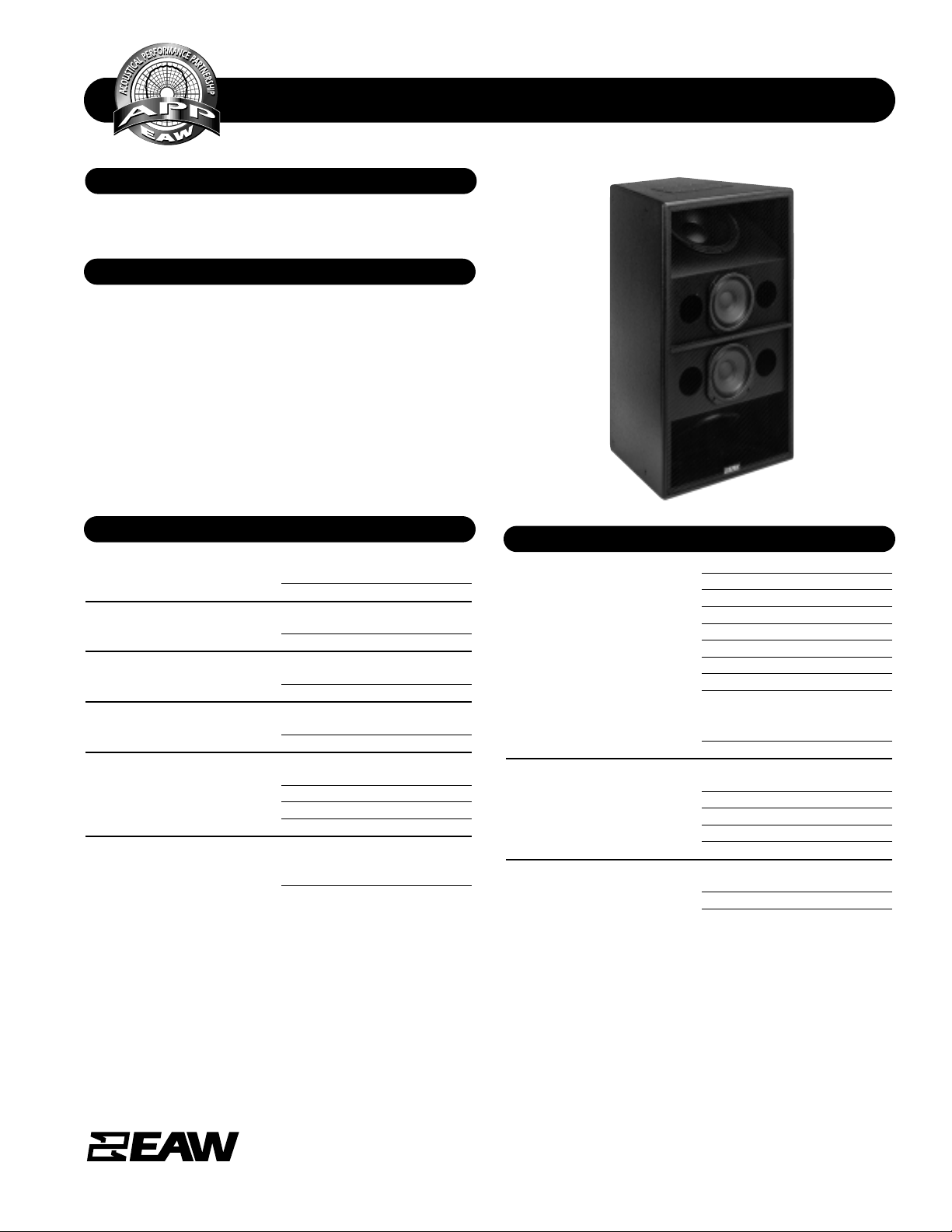
A unique 2 way bass system employing Tuned Dipolar Array
Technology. Includes 2x 12" Woofers (vented) and 2x 8"
woofers (sealed) in a trapezoidal enclosure.
The MQTD412 uses patented Tuned Dipolar Array (TDA)
Technology to achieve unprecedented LF directivity in the
vertical plane without enormous horns or baffles. The compact, high output LF system works with MQ Series mid/high
modules to create true 3-way arrays in large format installations. A powerful tool wh ere LF dir ectivity is requir ed. Six year
warranty.
Applications include:
Stadiums Arenas
Dance Clubs Large Theaters
Large Houses of Worship
SPECIFICATIONS MQTD412
DESCRIPTION
PERFORMANCE
One Main Street, Whitinsville, MA 01588 508 234 6158 Toll Free 800 992 5013 FAX 508 234 8251 info@eaw.com www.eaw.com
EAW products are continually improved. All specifications are therefore subject to change without notice. MQTD412/888173 Rev(1)/2 pp 7/25/00 Printed in USA
APPLICATION
PHYSICAL
LF Subsystem 2x 12-in, vented
2x 8-in, sealed
Configuration Dedicated LF tuned dipolar array
Powering Mode Bi-amplified
Cabinet Type (shape) Trapezoidal
Enclosure Materials Baltic birch plywood
Finish
Wear-resistant textured black paint
Connectors 2x 4-Terminal barrier strip
Suspension Hardware (16) 3/8”-16 threaded mounting
points (4 each top, bottom, and
sides )
Grille Powder coated perforated steel
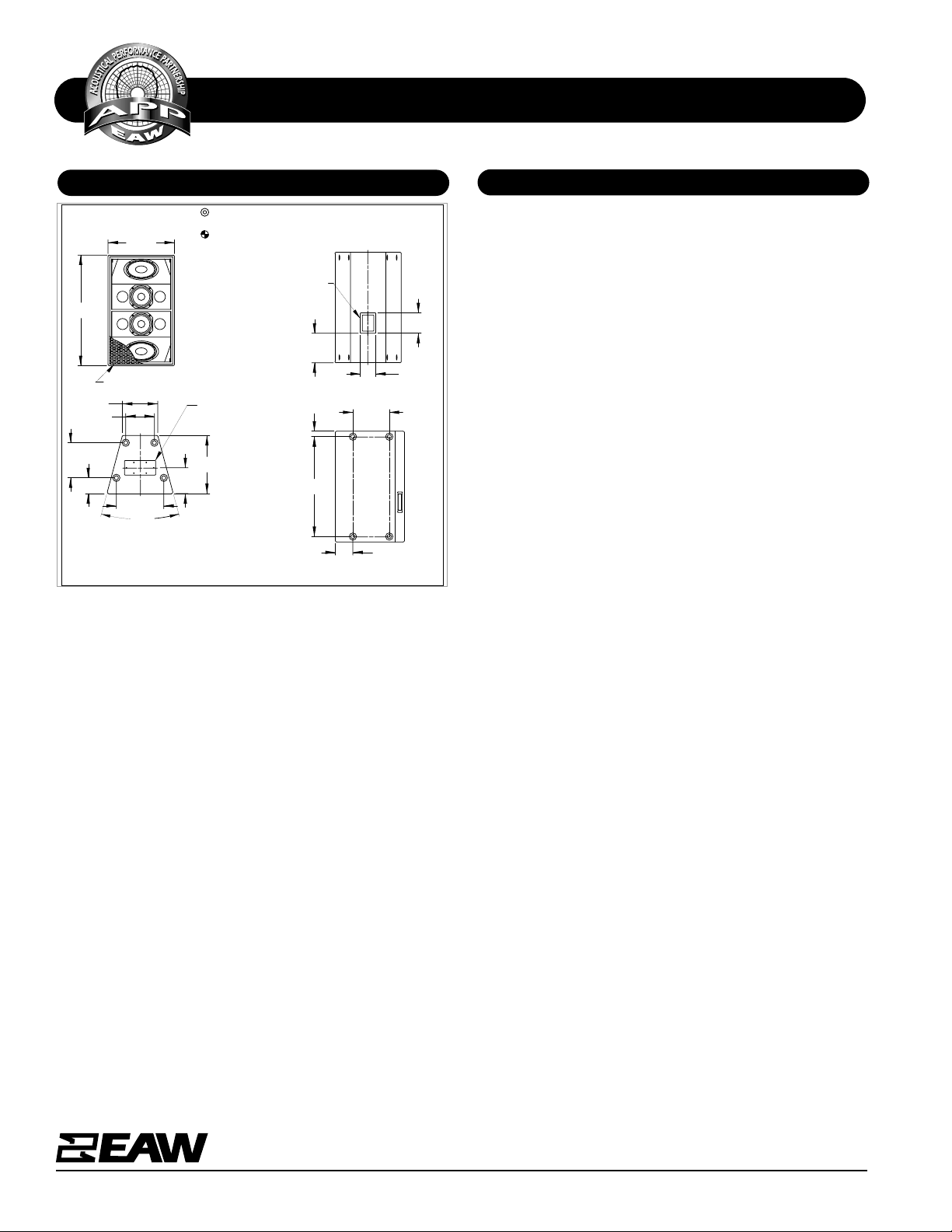
Dimensions inches millimeters
Height 40.00 1016
Width (front) 24.0 610
Width (rear) 12.75 324
Depth 21.0 533
Trapezoid Angle 15°
Weights pounds kilograms
Net Weight 150 68.0
Shipping Weight 162 73.5
SPECIFICATIONS MQTD412
DIMENSIONAL DRAWING
A & E SPECIFICATIONS
One Main Street, Whitinsville, MA 01588 508 234 6158 Toll Free 800 992 5013 FAX 508 234 8251 info@eaw.com www.eaw.com
EAW products are continually improved. All specifications are therefore subject to change without notice. MQTD412/888173 Rev(1)/2 pp 7/25/00 Printed in USA
The low frequency loudspeaker systems shall incorporate 2x
12-in plus 2x 8-in LF transducers. Each driver pair shall be
spaced so as to create a tuned dipolar array. The driver pairs
shall require an active crossover at 250 Hz, 24 dB/octave. The
system shall provide 10-12 dB attenuation 90° off axis (v)
from 160 Hz to 500 Hz.
System frequency respon se shall vary no m ore than ±3 dB from
58 Hz to 500 Hz measured on axis. The 12-in driver pair shall
produce a Sound Pressure Level (SPL) of 101 dB SPL on axis
at 1 meter with a power input of 1 Watt, and shall be capable
of produ cing a peak output of 137 SPL on axis at 1 meter. The
12-in driver pair shall handle 1000 Watts of amplifier power
(AES Standard) and shall have a nominal impedance of 2x 8
Ohms.
The 8-in driver pair shall prod uce a Soun d Pressur e Level (SPL)
of 101 dB SPL on axis at 1 meter with a power input of 1 W att,
and shall be capable of producing a peak output of 133 SPL
on axis at 1 meter. The 8-in driver pair shall handle 400 Watts
of amplifier power (AES Standard) and shall have a nominal
impedance of 2x 12 Ohms.
The loudspeaker enclosure shall be trapezoidal in shape. It
shall be constructed of 1/2-in thi ckness void-free cross-gr ainlaminated Baltic birch plywood and shall employ extensive
internal bracin g. It shall be finished in wear-r esistant te xtured
black paint. Input connectors shall be dual four-terminal barrier strips. A total of sixteen 3/8"-16 Threaded Mounting
Points (4 each top, bottom, and sides) shall be provided. The
front of the loudspeaker shall be covered with a powder coated perforated steel grille.
The low frequency loudspeaker shall be the EAW model
MQTD412.
Manufacturing tolerances are +/- 0.13 and +/- 1°
TOP/BOTTOM
FRONT
SIDES
BACK
509001 (A)
exp 3/29/00 dpm
MQTD412
DIMENSIONS APPLY
TO TOP & BOTTOM
10.34
C
L
(12.75)
5.68
9.31
21.00
30°
17.15
ACCESS PANEL
L
C
10.69
5.62
7.38
INPUT
6.37
1.95
36.10
13.15
24.00
GRILLE PARTIALLY SHOWN
40.00
INDICATES MOUNTING POINT,
3/8-16 THREADED HOLE (PI ANGLE).
INDICATES CENTER OF BALANCE.
 Loading...