

EAW MQH1344e User Manual
Frequency Response
±3 dB 75 Hz to 15 kHz
-10 dB 43 Hz
Axial Sensitivity (dB SPL, 1 Watt @ 1m)
LowerLF 92
Upper LF 94
MF 111
HF 111
Impedance (Ohms)
Lower LF 8
Upper LF 8
MF 8
HF 8
Power Handling, AES Standard (Watts)
Lower LF 600
Upper LF 600
MF 400
HF 150
Calculated Maximum Output (dB SPL @ 1m)
Lower LF Peak 126.0
Upper LF Peak 128.0
MF Peak 143.0
HF Peak 139.0
Lower LF Long Term 120.0
Upper LF Long Term 122.0
MF Long Term 137.0
HF Long Term 133.0
Nominal Coverage Angle, -6 dB Points (degrees)
Horizontal 40
Vertical 40
Recommended High-Pass Frequency
24 dB/Octave 45 Hz
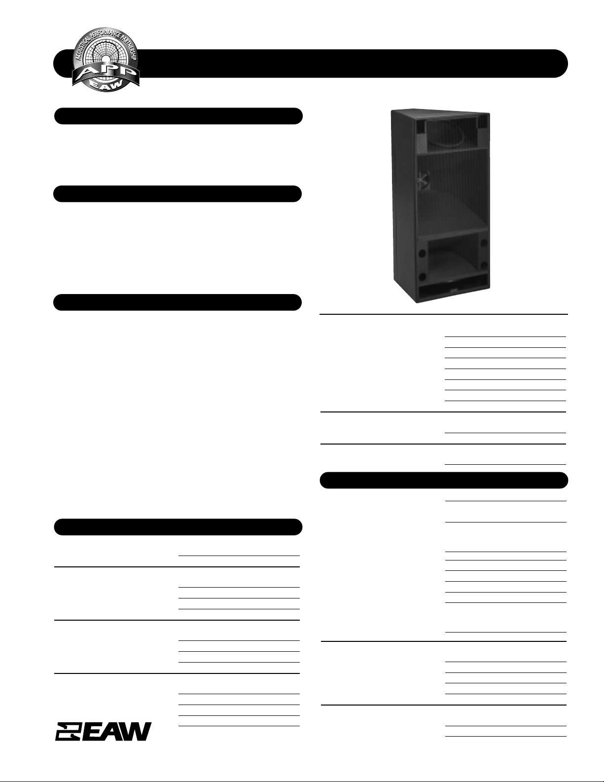
• Full-range, 3-way system
• 2x slot-loaded 15-in LF; horn-loaded 10-in MF; 2-in
Neodymium HF
• LF woofers spaced for directional control to below 200 Hz
• Asymmetrical (down-angled) 40° x 40° beamwidth
A 3-way, quad-amplified full-range system in a vented trapezoidal enclosure. Includes dual, slot-loaded 15-in woofers, a
horn-loaded 10-in MF cone with Radi al Phase Plug™, and a 2in exit/3-in diaphragm Neodymium compression driver. The
MF and HF horns provide an asymmetrical 40° x 40°
beamwidth. The enclosure is vertically configured for arraying in horizontal rows, and features a comprehensive system
of 3/8”-16 threaded suspension points.
The MQH1344e represents a highly specialized approach
developed to solve difficulties in larger venues. It provides
unique, down-angled coverage by using specially designed
asymmetrical MF and HF horns. Dual 15-in woofers are separated at an optimal distance to provide significant off-axis
attenuation to below 200 Hz. To avoid problematic lobing in
the upper LF range, discrete signal processing reduces the
input to one LF driver while allowing th e oth er to continue to
work up into the lower midrange. This more evenly matches
the MF horns beamwidth while assisting in maintaining pattern control through the entire crossover region. The
MQH1344e requires four separate amplifier channels (quadamplification) and digital signal processing in order to
achieve the pattern control described.
Application Usage: Install
Houses of Worship Auditoriums Theatres
Performing Arts Centers Arenas Stadiums
SPECIFICATIONS MQH1344e
FEATURES
DESCRIPTION
PERFORMANCE
One Main Street, Whitinsville, MA 01588 508 234 6158 Toll Free 800 992 5013 FAX 508 234 8251 info@eaw.com www.eaw.com
EAW products are continually improved. All specifications are therefore subject to change without notice. MQH1344e/0002684/2 pp April 2002 Printed in USA
APPLICATION
PHYSICAL
LF Subsystem 2x 15-in cones, vented
MF Subsystem 10-in horn loaded cone, Radial
Phase Plug™
HF Subsystem 1x 2-in exit/3-in diaphragm
compression driver on a constant
directivity horn
Configuration 3-way, full-range
Powering Quad-amplified
Enclosure Material
Exterior grade Baltic birch plywood
Finish
Wear-resistant textured black paint
Connectors Terminal barrier strip
Suspension Hardware 16x 3/8”-16 threaded mounting
points (4 each on top, bottom
and sides)
Grille Powder coated perforated steel
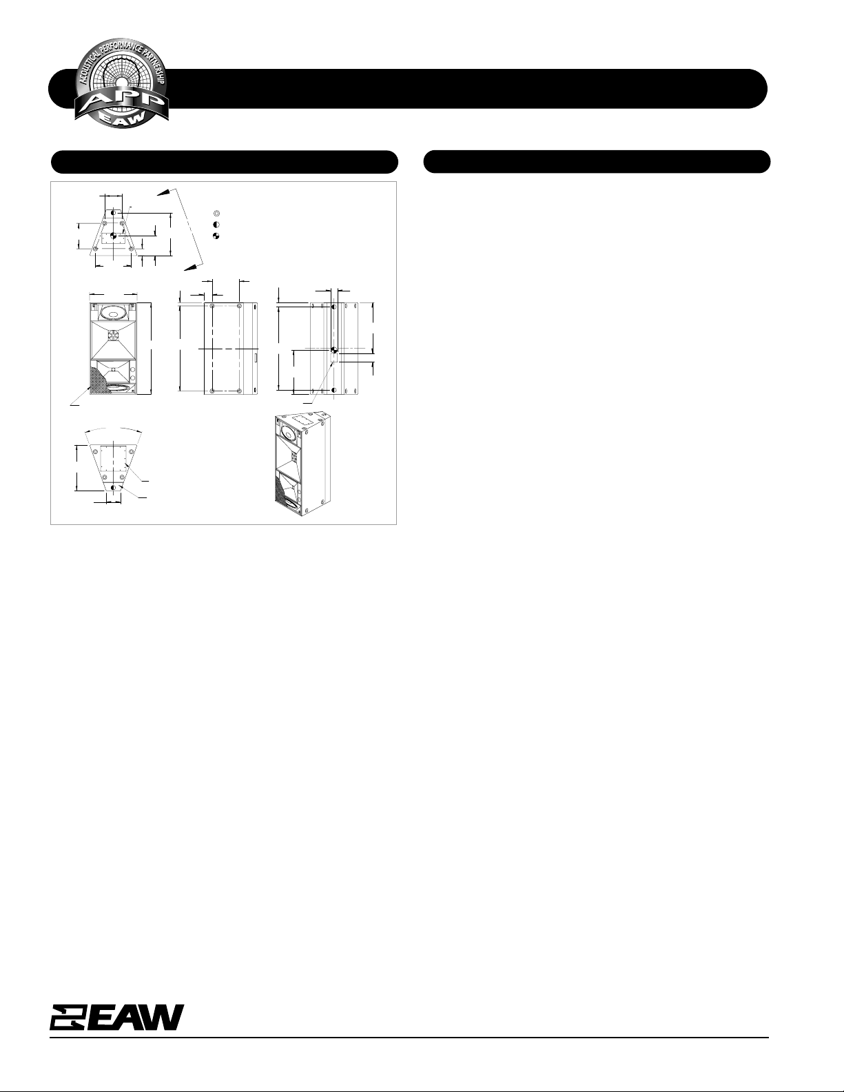
Dimensions inches millimeters
Height (front) 54.0 1372
Height (rear) 28.0 711
Width 8.4 213
Depth 27.0 686
Trapezoid Angle 20 degrees per side
Weights pounds kilograms
Net Weight 225 102.3
Shipping Weight 253 115.0
SPECIFICATIONS MQH1344e
DIMENSIONAL DRAWING
A & E SPECIFICATIONS
One Main Street, Whitinsville, MA 01588 508 234 6158 Toll Free 800 992 5013 FAX 508 234 8251 info@eaw.com www.eaw.com
EAW products are continually improved. All specifications are therefore subject to change without notice. MQH1344e/0002684/2 pp April 2002 Printed in USA
The 3-way full-range loudspeaker shall incorporate 2x 15-in
slot-loaded woofers, a 10-in MF cone with Radial Phase
Plug™, and a 2-in exit/3-in diaphragm HF compression driver.
The MF and HF devi ces shall be loaded on asymmetri cal, downangled horns with a 40° x 40° beamwidth. The LF woofers
shall be optimally spaced to provid e signifi cant o ff-axis attenuation to below 200 Hz.
System frequency respon se shall vary no m ore than 63 dB from
75 Hz to 15 kHz measured on axis. The lower LF section shall
produce a soun d pressur e level of 92 dB SPL on axis at 1 m eter
with a power input of 1 watt, and shall be capable of producing a peak output of 126 dB SPL on axis at 1 meter. The upper
LF section shall produce a sound pressure level of 94 dB SPL
on axis at 1 meter with a power input of 1 watt, and shall be
capable of producing a peak output of 128 dB SPL on axis at
1 meter. The MF section shall produce a sound pressure level
of 111 dB SPL on axis at 1 meter with a power input of 1 watt,
and shall be capable of prod ucin g a peak output of 143 dB SPL
on axis at 1 meter. The HF section shall produce a sound pressure level of 111 dB SPL on axis at 1 meter with a power input
of 1 watt, and shall be capable of producing a peak output of
139 dB SPL on axis at 1 meter. Both LF sections shall handle
600 watts of amplifier power (AES Standard) and shall have a
nominal impedance of 8 ohms. The MF section shall handle
400 watts of amplifier power (AES Standard) and shall have a
nominal impedance of 8 ohms. The HF section shall handle
150 watts of amplifier power (AES Standard) and shall have a
nominal impedance of 8 ohms.
The loudspeaker enclosure shall be trapezoidal in shape. It
shall be constructed of e xterior grad e Baltic bir ch plywood and
shall employ extensive intern al br acin g. I t shall be finish ed in
wear-resistant textur ed black paint. Input connectors shall be
a terminal strip. A total of 16x 3/8”-16 threaded
mounting/suspension points (4 each top, bottom, and sides)
shall be provided. The front of the loudspeaker shall be covered with a powder coated perforated steel grille.
The 3-way full-range loudspeaker shall be the EAW model
MQH1344e.
Manufacturing tolerances are +/- 0.13 and +/- 1°
C
40°
C
L
L
A
ACCESS PANEL
11.75
4.00
54.00
ACCESS PANEL
ACCESS PANEL
25.16
(1.95)
50.10
NOTES:
1. SYMBOL INDICATES MOUNTING POINT,
3/8-16 THREADED HOLE (PI ANGLE).
2. SYMBOL INDICATES NON LOAD BEARING
MOUNTING POINT, 3/8-16 THREADED HOLE
3. SYMBOL INDICATES CENTER OF BALANCE.
4. WEIGHT APPROX. 225 LBS.
5. SHIPPING WEIGHT APPROX. 253 LBS.
A
15.96
4.93
C
L
VIEW A-A
DIMENSIONS APPLY
TO BOTH SIDES
MQH1344e
10.25
15.00
21.17
TOP
DIMENSIONS APPLY
TO TOP AND BOTTOM
28.00
GRILLE PARTIALLY SHOWN
FRONT
27.00
(8.35)
BOTTOM
(2.53)
48.94
26.75
INPUT
(PI ANGLE).
4.00
C
L
29.94
C
L
5.00
BACK
 Loading...