

A
C
O
U
S
T
I
C
A
L
P
E
R
F
O
R
M
A
N
C
E
P
A
R
T
N
E
R
S
H
I
P
TECHNICAL SPECIFICATIONS KF860
DESCRIPTION
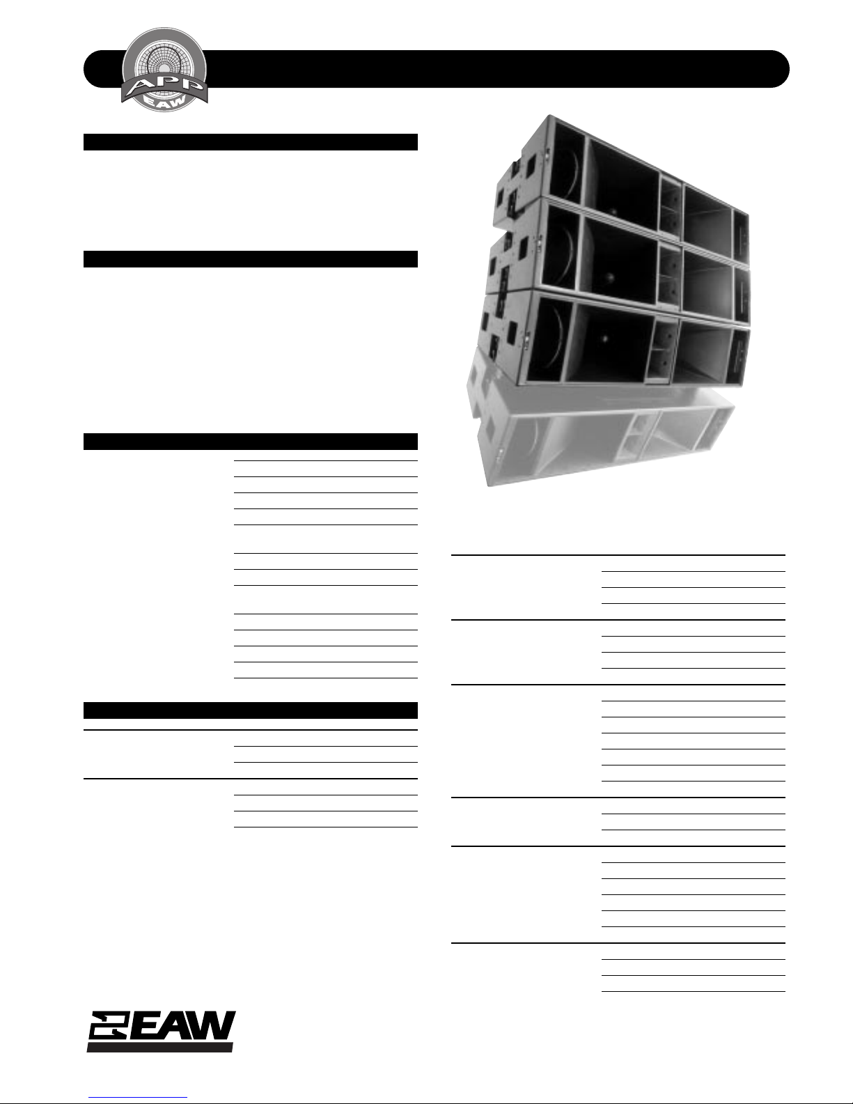
A 3-way triamp full range system in a trapezoidal vertically
arrayable enclosure. Includes 2x 15-in woofers (“tuned” for
dipolar directivity), 2x horn-loaded 10-in midrange cones
and 2x 2-in exit compression drivers on separate 60 x 30
constant directivity horns.
APPLICATIONS
The KF860 Virtual Line Arr ay module is en gineer ed for use in
vertical arrays of n o less than three and as man y as 12 units.
DSP-driven Tuned Dipolar Array effects create outstanding
off-axis rejection to 100 Hz and below. Unique rigging system provides a new level of accuracy and repeatability. The
system of choice f or televised live events . Six year warranty.
Applications include:
Major Televised Events
Concert Tours
DESCRIPTIVE DATA
Part Number 999274
Product Group V
LF Subsystem & Loading 2x 15-in, Angled Baffles
MF Subsystem & Loading 2x 10-in Cone, Horn Loaded
HF Subsystem & Loading 2x 2-in Exit Compression Driver on
Constant Directivity Horn
System Configuration 3-way, Full Range
Powering Configuration(s) Triamplified via MX 8600 Processor
Recommended High-Pass
Frequency (24 dB/Octave) 30Hz
Cabinet Type (shape) Horizontal Trapezoidal
Enclosure Materials Baltic Birch Plywood
Finish Black Catalyzed Polyurethane
Connectors One each male and female AP6
Grill Vinyl Coated Perforated Steel
NOMINAL DATA
Frequency Response (Hz)
±3 db 50Hz to 17kHz
-10 dB 40Hz
Axial Sensitivity (dB SPL/1 Watt/1m)
LF 102
MF 112
HF 115
Three KF860’s shown in an array with a KF861.
Impedance (Ohms)
LF 4
MF 4
HF 5
Power Handling (Watts)
LF AES Standard 2000
MF AES Standard 800
HF AES Standard 400
Calculated Maximum Output (dB SPL, @ 1m)
LF Peak 141.0
MF Peak 147.0
HF Peak 147.0
LF Long Term 135.0
MF Long Term 141.0
HF Long Term 141.0
Nominal Coverage Angle / -6 dB points (degrees)
Horizontal 60
Vertical 30
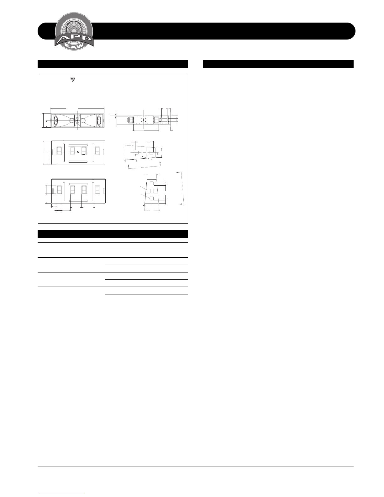
Dimensions inches millimeters
Height (front) 18.5 470
Height (rear) 12.875 327
Width 72 1829
Depth 32 813
Trapezoid Angle 5 degrees per side
Weights pounds kilograms
Net Weight 363 165.2
Shipping Weight 375 170.6
EASTERN ACOUSTIC WORKS
One Main Street, Whitinsville, MA 01588 • (508) 234 - 6158 • FAX (508) 234 - 8251 • Email info@eaw.com • Web http://www.eaw.com
EAW products are continually improved. All specifications are therefore subject to change without notice. • PUB# KF860-888053 (A)/2 pp/1/29/99 • Printed In USA
A
C
O
U
S
T
I
C
A
L
P
E
R
F
O
R
M
A
N
C
E
P
A
R
T
N
E
R
S
H
I
P
TECHNICAL SPECIFICATIONS KF860
DIMENSIONAL DRAWING ARCHITECTURAL SPECIFICATIONS
DIMENSIONAL DRAWINGS
INDICATES 3" FLYTRACK STRIP.
KF860
18.49
9.24
32.00
17.11
10.81
TYP
13.22
TYP
7.21
6.44 TYP
510315
exp 11/1/96 shb
CENTER OF BALANCE.
5. TOP AND BOTTOM ARE IDENTICAL EXCEPT RUNNERS PROTRUDE 1/4" ON
BOTTOM, AND RUNNER MATING CHANNELS ARE RECESSED 1/8" ON TOP.
6. BUILT-IN HANDLES ( 2 PLACES EACH SIDE).
7. BUILT-IN RIGGING ATTATCHMENT POINTS (2 PLACES EACH SIDE).
ALL DIMENSIONS ARE IN INCHES UNLESS OTHERWISE NOTED.
72.00
C
L
FRONT
TOP
( BOTTOM SEE NOTE 5)
15.13
18.00
11.56
VIEW A-A
ROTATED HORIZONTALLY FOR CLARITY TYP 2 PLCS
2.06 X 2
6.44
34.00
10° 12.88
.25
A
SEE NOTE 7
SEE NOTE 6
C
L
BACK
19.87 4.41
SEE NOTE 6
.25
RIGHT SIDE
SERVICE ITEMS
LF: Complete Cone Dirver
EAW Part No. 804036
MF: Complete Cone Driver
EAW Part No. 804022
HF: Complete Compression Driver/Tweeter
EAW Part No. 803011
Filter/Crossover Network: Complete Assembly
EAW Part No. 201431
7.69
15.81
4.50 SQ. TYP.
SEE NOTE 7
A
12.88
4.50 SQ. TYP
19.88
4.38
10º
4.31
4.31
4.25
SIDE
A
A
The three-way full ran g e lou dspeak er system s shall incorporate 2x 15-in LF transducers, 2x 10-in cone MF transducers
and 2x 2-in exit compression driver HF transducer.
The LF drivers shall be separated by a “tun ed” distan ce that
uses the Tuned Dipolar Array effect to achieve optimal low
frequency pattern control. Each MF driver shall be loaded
into a midr an g e h orn constructed of 3mm birch plywood reinforced with high density polyurethane foam. The MF horn
shall incorporate a phase/displacemen t plug. Each HF driver
shall be loaded on a constant directivity horn with a nominal coverage pattern of 60° (h) x30° (v).
System frequency response shall vary no more than ±3 dB
from 50 Hz to 17 kHz measured on axis. The low frequency
section shall produ ce a Sound Pressure Level (SPL) o f 102 dB
SPL on axis at 1 meter with a power input of 1 Watt, and
shall be capable of producing a peak output of 141 SPL on
axis at 1 meter . It shall handle 2000 W atts of amplifier power
(AES Standard) and shall have a nominal impedance of 4
Ohms. The mi drang e frequency section shall pr oduce a Sound
Pressure Level (SPL) of 112 dB SPL on axis at 1 m eter with a
power input of 1 Watt, and shall be capable of producing a
peak output of 147 SPL on axis at 1 meter. It shall handle
800 Watts of amplifi er power (AES Stan dard) and shall have
a nominal impedan ce of 4 Ohms . The hi gh frequen cy section
shall produce a Soun d Pressure Level (SPL) o f 115 dB SPL on
axis at 1 meter with a power input of 1 Watt, and shall be
capable of producing a peak output of 147 SPL on axis at 1
meter. It shall handle 400 Watts of amplifier power (AES
Standard) and shall have a nominal impedance of 5 Ohms.
The loudspeaker enclosure shall be trapezoidal in shape. It
shall be constructed of 15mm thi ckness void-free cr oss-grainlaminated Baltic birch plywood and shall employ extensive
internal bracin g. It shall be finished in black catalyzed polyurethane. Input connectors shall be one each male and female AP6. The enclosur e shall includ e oval steel tubing (on e
tube on each side) that accepts steel linking plates. The
plates shall attach to the steel tubing with quick-release
pins which shall be inclu ded. Suffici ent precisely ali gned pin
holes shall be placed in the steel tubing and linking plates
to allow for a variety of arraying angles and spacing. The
front of th e loudspeaker shall be cover ed with a vinyl coated
perforated steel grill backed with open cell foam to protect
against dust.
The three-way full ran ge loudspeaker shall be th e EAW m odel
KF860.
Acoustic Performance Partnership Eastern Acoustic Works KF860
One Main Street, Whitinsville MA, 0158 8 USA • Phone 508/234-6158 • Toll Free 800/992-5013 • Fax 508/234-8251 • Web http://www .eaw.com • email info@eaw.com
 Loading...