

SPECIFICATIONS KF855
PHYSICAL
One Main Street, Whitinsville, MA 01588 508 234 6158 Toll Free 800 992 5013 FAX 508 234 8251 info@eaw.com www.eaw.com
EAW products are continually improved. All specifications are therefore subject to change without notice. KF855/888052(B)/2 pp 5/1/00 Printed in USA
DESCRIPTION
PERFORMANCE
FEATURES
APPLICATION
• VA™ MF/HF downfill system
• 10-in MF on asymmetrical horn
• 2x 2-in exit HF on separate horns with separate
coverage areas
• Frequency shading integrates HF horns when
powered together
• Power HF horns separately for maximum control
• For portable use only
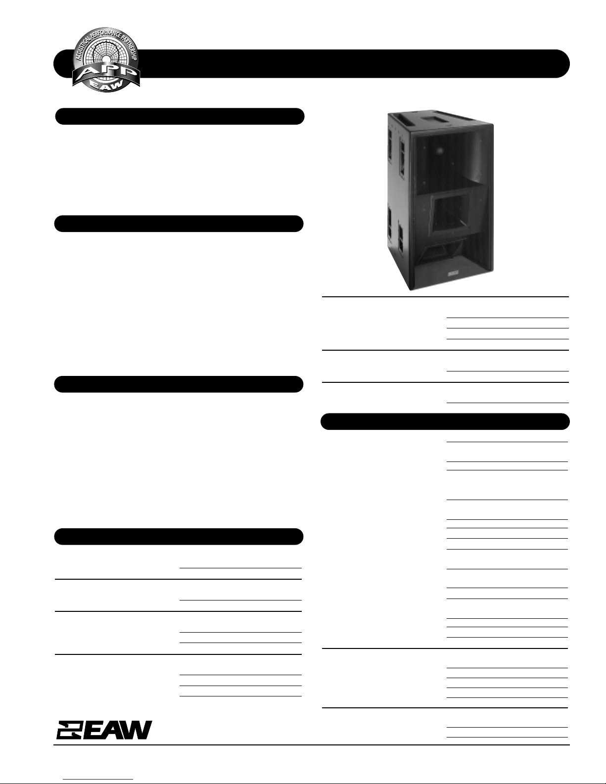
A complex 2-way mid/high system in a multi-baffle trapezoidal enclosure designed for down fill from a flown EAW
Stadium Array. Includes a horn-loaded 10-in cone (down
angled 10 degrees) and 2x 2-in exit compression drivers on
separate constant directivity horns. Th e two HF horns (angled
down 10 and 45 degrees) may be powered separately or in
parallel with complex internal passive filter providing frequency shading to integrate the two horns. Powering mode is
switchable: biamplified (HF horns in parallel with internal filter and powered by a single amp channel) or biamplified (HF
horns powered separately). When in parallel mode, a switch
allows attenuation of the lower (45°) HF horn according to
trim heig ht.
The KF855 is engineered to serve as the downfill loudspeaker
in an EAW concert touring Stadium Array, providing coverage
to the most expensive front row seats. The two HF horns may
be powered separately or in parallel. The system may be
inverted to reach balconies in converted ‘movie palaces’ or
similar venues. Six year warranty.
Applications include:
Concert Tours Corporate Events
Large Theaters Stadiums
Cathedrals Live Music Clubs
Frequency Response (1 Watt @ 1m)
±3 db 200 Hz to 17 kHz
-10 dB 170 Hz
Axial Sensitivity (dB SPL, 1 Watt @ 1m)
MF 109
HF 112
Impedance (Ohms)
MF 8
HF 7 (Horns in parallel)
2x 12 (horns seperate)
Power Handling, AES Standard (Watts)
MF 400
HF 2x 200 (horns seperate)
1x 400 (horns parallel)
Calculated Maximum Output (dB SPL @ 1m)
MF Peak 141.0
HF Peak 141.0
MF Long Term 135.0
HF Long Term 135.0
Nominal Coverage Angle, -6 dB points (degrees)
Horizontal 55
Vertical
70 (+10,-60 from horizontal axis)
Recommended High-Pass Frequency
24 dB/Octave 250Hz (for use with KF850EF)
MF Subsystem 1x 10-in horn loaded cone
HF Subsystem 2x 2-in exit compression driver
on horn
Configuration 2-way, mid/high, downfill
Powering Switchable: Bi-amp (HF horns
parallel) or bi-amplified (HF
horns powered separately)
Controls (switches, knobs) Downfill powering mode and
attenuation switching
Cabinet Type (shape) Trapezoidal with angled baffles
Enclosure Materials Baltic birch plywood
Finish Black catalyzed polyurethane
Connectors Parallel Horns: 1 each male and
female AP6
Independent Horns: 2 each male
and female AP6
Suspension Hardware 2X 19-position flytrack (top)
Grille Vinal coated perforated steel,
foam backed
Options 179001 flyclip with ring
179002 flyclip with hook
255010 caster pallet CP850
Dimensions inches millimeters
Height 42 1067
Width (front) 26.38 670
Width (rear) 16.5 419
Depth 29.5 749
Trapezoid Angle 9.5°
Weights pounds kilograms
Net Weight 240 109.2
Shipping Weight 252 114.7
SPECIFICATIONS KF855
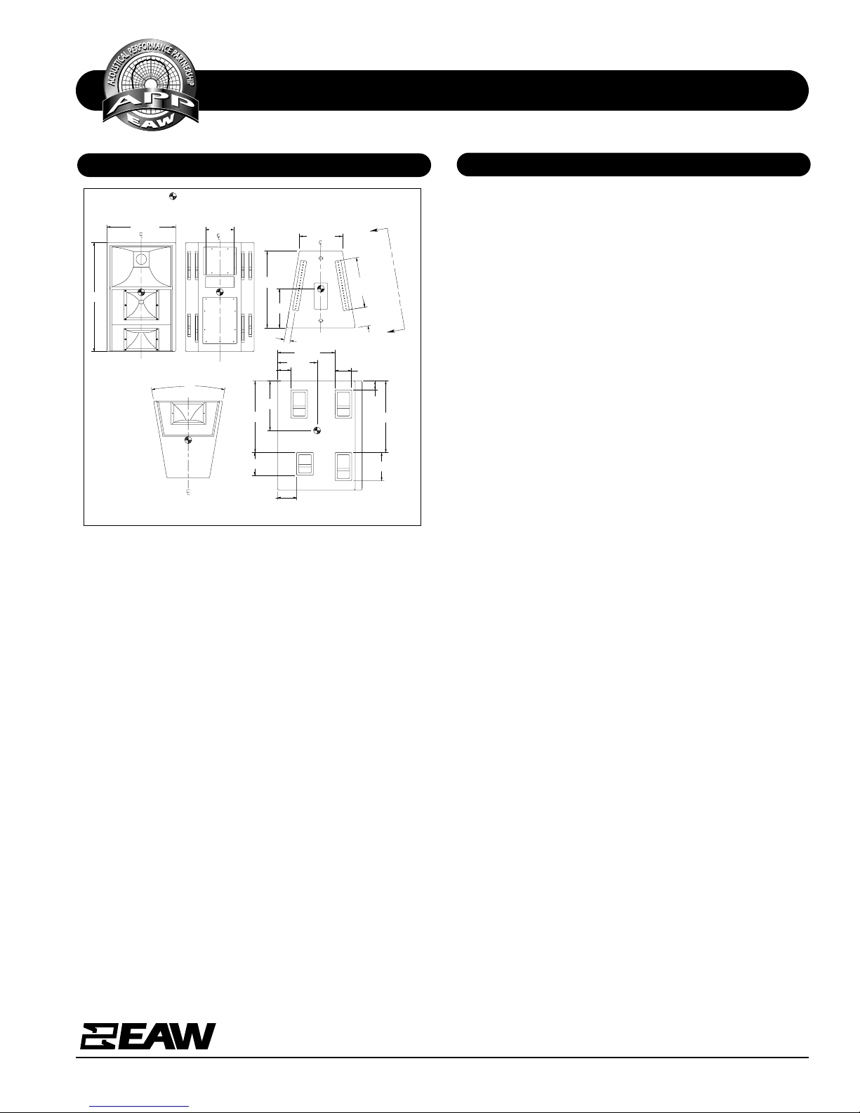
DIMENSIONAL DRAWING
A & E SPECIFICATIONS
One Main Street, Whitinsville, MA 01588 508 234 6158 Toll Free 800 992 5013 FAX 508 234 8251 info@eaw.com www.eaw.com
EAW products are continually improved. All specifications are therefore subject to change without notice. KF855/888052(B)/2 pp 5/1/00 Printed in USA
Manufacturing tolerances are +/-0.13 and +/-1°
10.81 (6X)
27.43
6.30 (8X)
3.43
11.00
7.25
29.50
19.25
16.50
15
FLYTRACK
A
A
VIEW A-A
BACK
26.36
FRONT
27.43
8.75
15.19
22.06
5.12
19
19°
2.30
TYP
TOP
BOTTOM
7.30
41.87
KF855
CENTER OF GRAVITYY.
CABINET IS SYMETRICAL ABOUT ITS CENTERLINES.
ALL DIMENSIONS IN INCHES UNLESS OTHERWISE NOTED.
510354
EXP 3/19/97 SHB
The two-way loudspeaker systems shall incorporate a 10-in
cone MF transducer and 2x 2-in exit compression driver HF
transducers.
The MF driver shall be loaded into a vertically asymetrical
midran ge horn constructed of 1/8-in birch plywood reinfor ced
with high density polyurethane foam. The MF horn’s asymmetrical shape shall direct MF en ergy d own at a nomin al angle
of 10°. The MF horn shall incorporate a phase/displacement
plug.
Each HF driver shall be loaded on a constant directivity horn
with a combined nominal coverage pattern of 55° (h) x 40°
(v). The two HF horns shall abut vertically . The upper HF horn
shall be angled down 10°. The lower HF horn shall be angled
down 45°. An internal passive filter n etwork shall provi de system equalization and frequency shading creating optimal
integration between the two HF horns.
The system shall include a switch allowing the two HF drivers
to be powered in parallel or separately. An control shall be
provided allowing the lower HF driver to be attenuated when
the two drivers are powered in parallel.
System frequency respon se shall vary no mor e than ±3 dB from
200 Hz to 17 kHz measured on axis. The mid frequency section shall produ ce a Soun d Pressure Level (SPL) of 109 dB SPL
on axis at 1 meter with a power input of 1 Watt, and shall be
capable of producing a peak output of 141 SPL on axis at 1
meter. It shall handle 400 Watts of amplifier power (AES
Standard) an d shall have a nomin al imped an ce o f 8 Ohms . Th e
high frequency section shall produce a Sound Pressure Level
(SPL) of 112 dB SPL on axis at 1 meter with a power input of
1 Watt, and shall be capable of producing a peak output of
141 SPL on axis at 1 meter. The HF section shall handle 200
Watts of amplifier power (AES Standard) and shall have a
nominal impedan ce of 7 Ohms when the secti on is powered in
parallel.
The loudspeaker enclosure shall be trapezoidal in shape. It
shall be constructed of 1/2-in thi ckn ess voi d-fr ee cr oss-gr ainlaminated Baltic birch plywood and shall employ extensive
internal bracing. It shall be finished in black catalyzed
polyurethane. Input connectors shall be three each male and
female AP6 (M/F for parallel HF section, dual M/F for separately powered HF sections). Two 19-in flytracks shall be
installed on the top of the enclosure. The front of the loudspeaker shall be covered with a vinyl coated perforated steel
grille backed with open cell foam to protect against dust.
The two-way mid/high loudspeaker shall be the EAW model
KF855.
 Loading...