

Page 1
EAWPilot
Page 2

Introduction To EAWPilot™
EAWPilot is an extremely fast and intuitive software created to aid the users of the UX8800, UX3600 + NT
products in evaluating, building, storing and recalling complex DSP congurations.
This manual has been created to help end-users step through the various pages and functions of
EAWPilot and access all of its powerful features.
Page 3
Windows Toolbar Overview
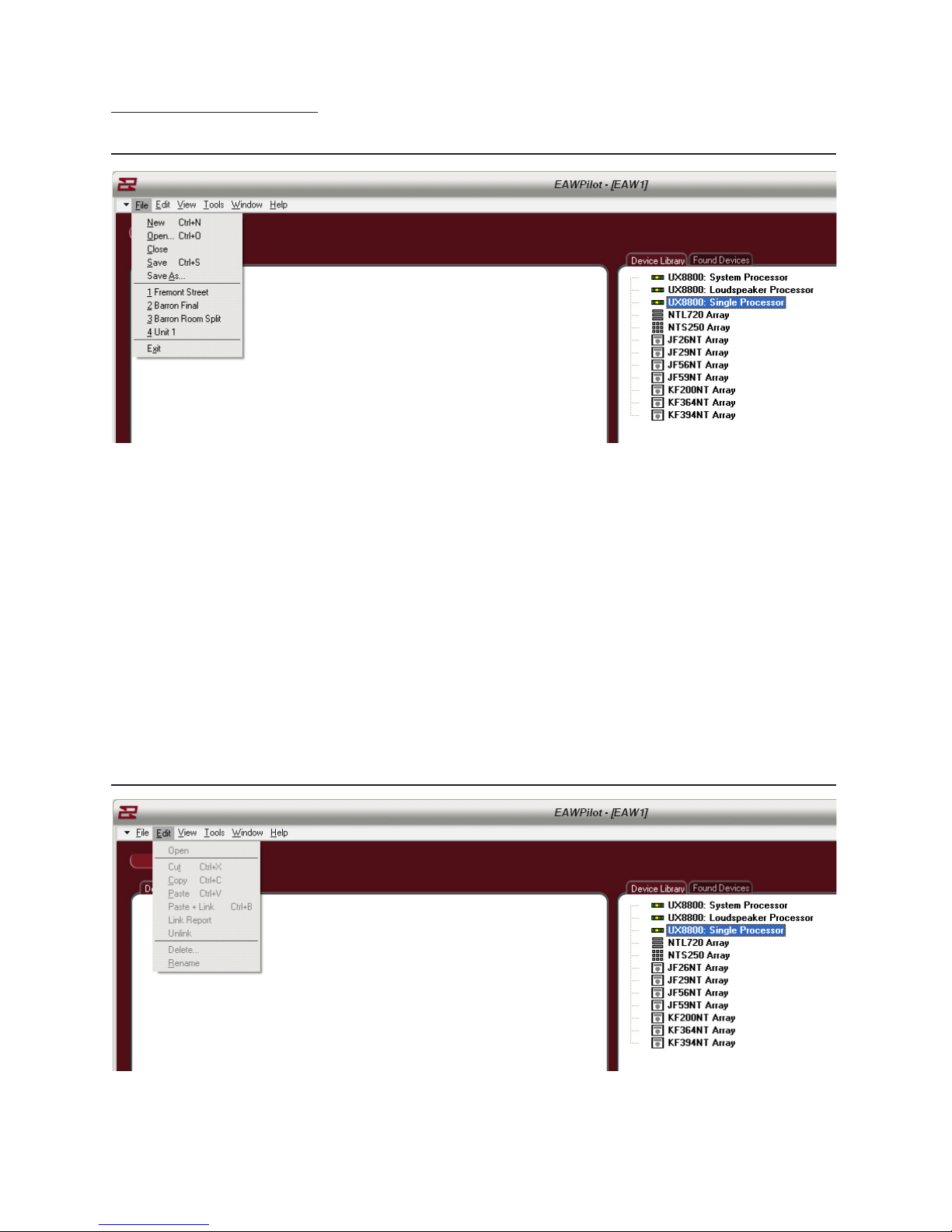
File Menu
New – Creates a new Pilot page. Multiple Pilot pages can exist simultaneously within the software.
Shortcut (Ctrl+N)
Open – Opens browser to load previously saved Pilot les. Shortcut (Ctrl+O)
Close – Closes current Pilot page
Save – Saves Current Pilot Page. Shortcut (Ctrl+S)
Save As – Allows saving of new le with name assignment
File List – Lists recently used les
Exit – Closes Pilot.
Edit Menu
Edit Menu not available until a device has been pulled into the “Design” column (coming up).
Page 4
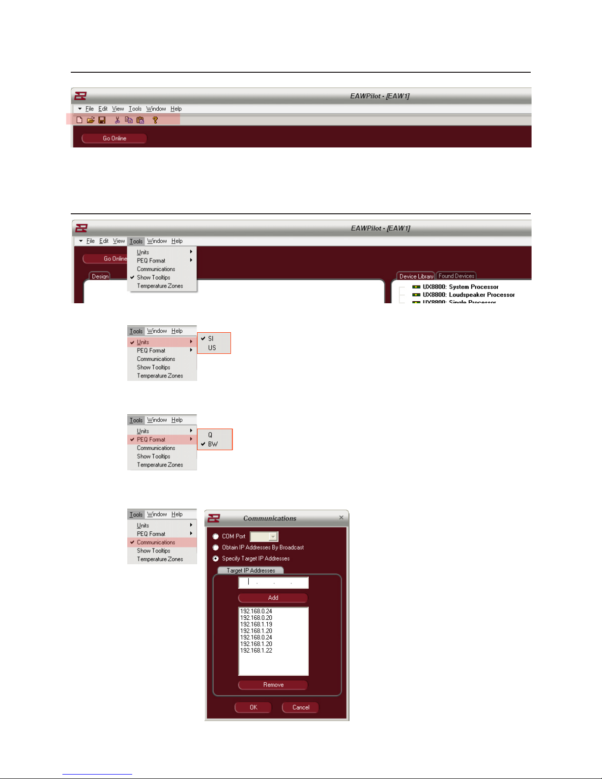
View Menu
Toggles Windows Toolbar On Or O
Tools Menu
Units – Select Between Imperial or Metric measurements
PEQ Format – Select Between Q or Bandwidth For Equalization
Communications – Opens Communication “Dialog” Box
Page 5
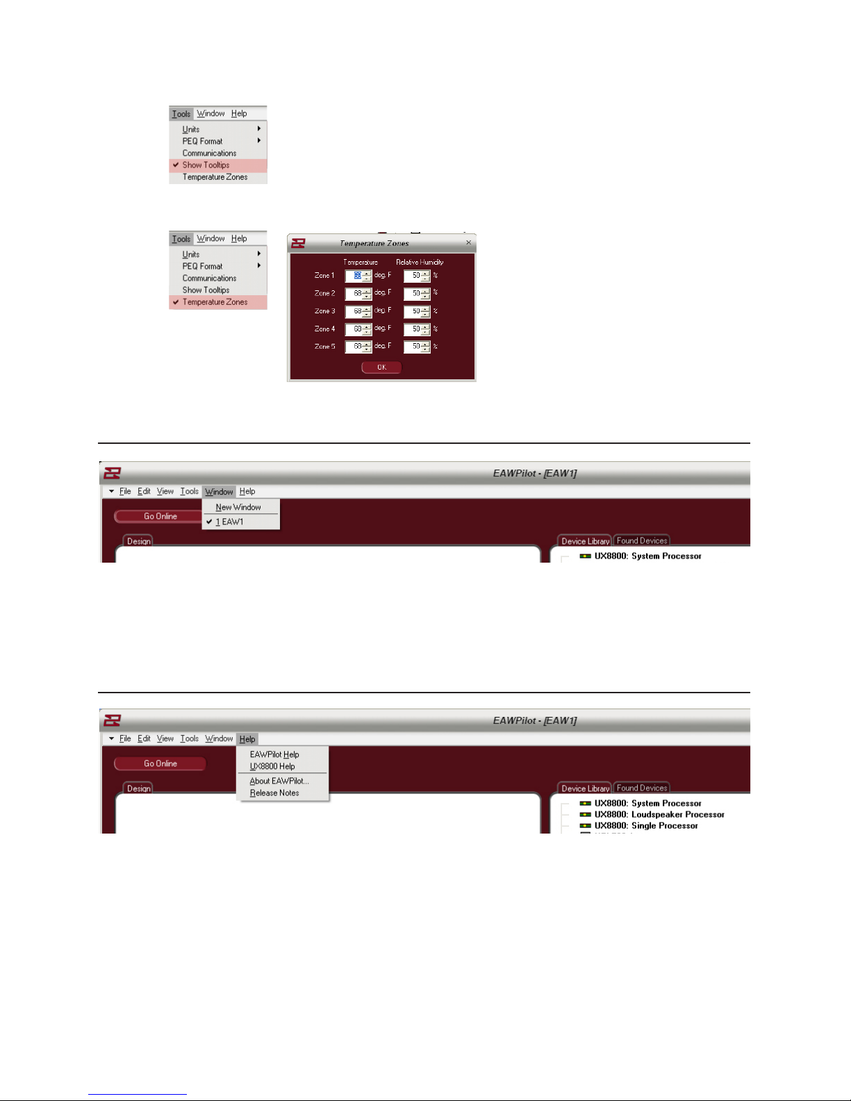
Show Tooltips – Interactive tooltips display
Temperature Zones - Allows multiple temperature / humidity zones to be created
Window Menu
Standard Windows Conguration Options
Help Menu
EAWPilotHelp – Opens The EAWPilot Help Files
UX8800Help – Opens The UX8800 Help Files
About EAWPilot – Displays Version Number Of The Pilot Software (good to keep up-to-date).
Release Notes – Updates made to this version
Page 6

The Ethernet Connection
System Connection via Ethernet
Connection to the UX8800 for laptop control is achieved using the ethernet port on the front of
the unit. This port is congured as a standard NIC (network interface card).
1) Cable: 8 conductor CAT5e cable or better
2) Mating Connector: RJ-45 male
3) Cable Conguration: Standard for connection to network hub or switch. Crossover type for
direct connection to computers NIC (supplied with unit).
Setting The UX8800 IP Address
1) Prior to connecting to a laptop computer, it is necessary to establish an IP Address on the
UX8800 so that it is recognized within the EAWPilot software.
2) Entering into the “Utilities” menu on the UX8800 and then “IP Address” will give you access to
the feature.
3) There will be four sets of numbers available to modify. The rst three numbers should be set
to 192.168.0. The last number can be set anywhere from 001 through to 256 conforming to a
small network protocol
4) It is not necessary to set a IP address for every device in the network. As long as the computer
is able to connect to the rst unit, all subsequent units in the same network will be discovered.
Device Name
Mode – System or Loudspeaker Processor
Input – A&B Analog or Digital
C&D Analog or Digital
UTIL
Temperature – Fahrenheit / Celsius
Humidity
Mute control on Prgrm. Load
(current, all, none)
LCD Contrast
Units – Imperial or Metric
IP Address
Front Panel Lock
About
Page 7
Setting A Static IP Address
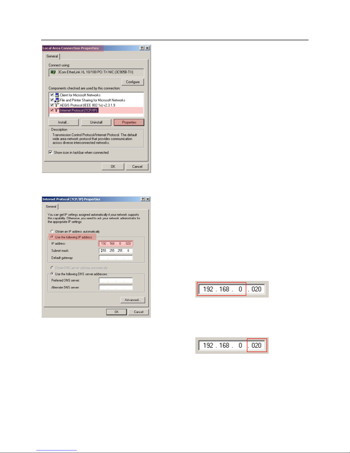
1) Locate the “Local Connection Properties” page on your
computer (Found Under “My Computer).
2) Go to “Internet Protocol (TCP/IP). Select it and click
on “Properties”.
This will open up the IP Properties Page where you can manually enter in a “static” IP Address for your
computer communication to the UX8800’s
3) Your computer will normally have the “Obtain an
IP Address Automatically” checkbox selected. We will
be setting our own IP Address manually so select the
checkbox labeled “Use The Following IP Address.
4) Now you will be able to enter in an address manually.
The rst three sets of digits must all match what
you enter into the EAWPilot software and UX8800
processor(s). Use the number sequences 192 . 168 . 0
in these cells.
5) The nal number will be the discrete Network IP for
the computer and hence the EAWPilot software.
The UX8800 must have a dierent number here
(From 001 – 256)
Page 8
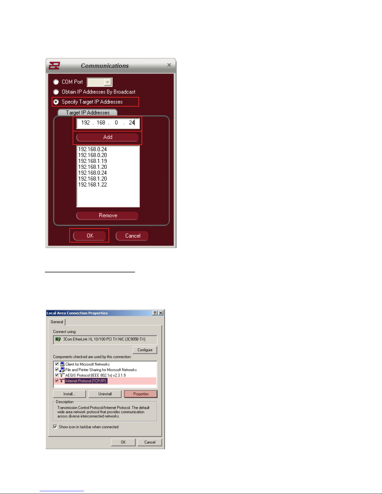
Now that the computer and hence EAWPilot has
a static IP Address, the address for the UX8800 or
multiple UX8800’s must be congured.
1) From the EAWPilot homepage, select “Tools”
and then “Communications”. This opens up the
“Dialog” menu within Pilot.
2) Check the box for “Specify Target IP Addresses”.
This puts EAWPilot into Static IP Address mode
3) In the Target IP Addresses number string, enter
the numbers exactly as you entered them on
the UX8800
4) Click the “Add” button to enter the IP Address
to the list. Then click “OK” to identify that this
is the IP Address that the computer will use to
communicate to the UX8800
Note: Multiple addresses can be entered in this
column for recognition from EAWPilot but it is
best to remove any unnecessary addresses as
EAWPilot will continue to search for them.
Setting A Dynamic IP Address
If you plan on using or installing multiple UX8800’s, you may want to consider using a Ethernet hub
which will act as a DHCP server and automatically congure IP addresses as long as the computer and
UX8800’s are set to dynamic mode.
Another option is to use Ethernet to communicate to the
rst unit and then U-Net to communicate to the others.
1) Locate the “Local Connection Properties”
page on your computer (Found Under “My
Computer).
2) Go to “Internet Protocol (TCP/IP). Select it and
click on “Properties”.
Page 9
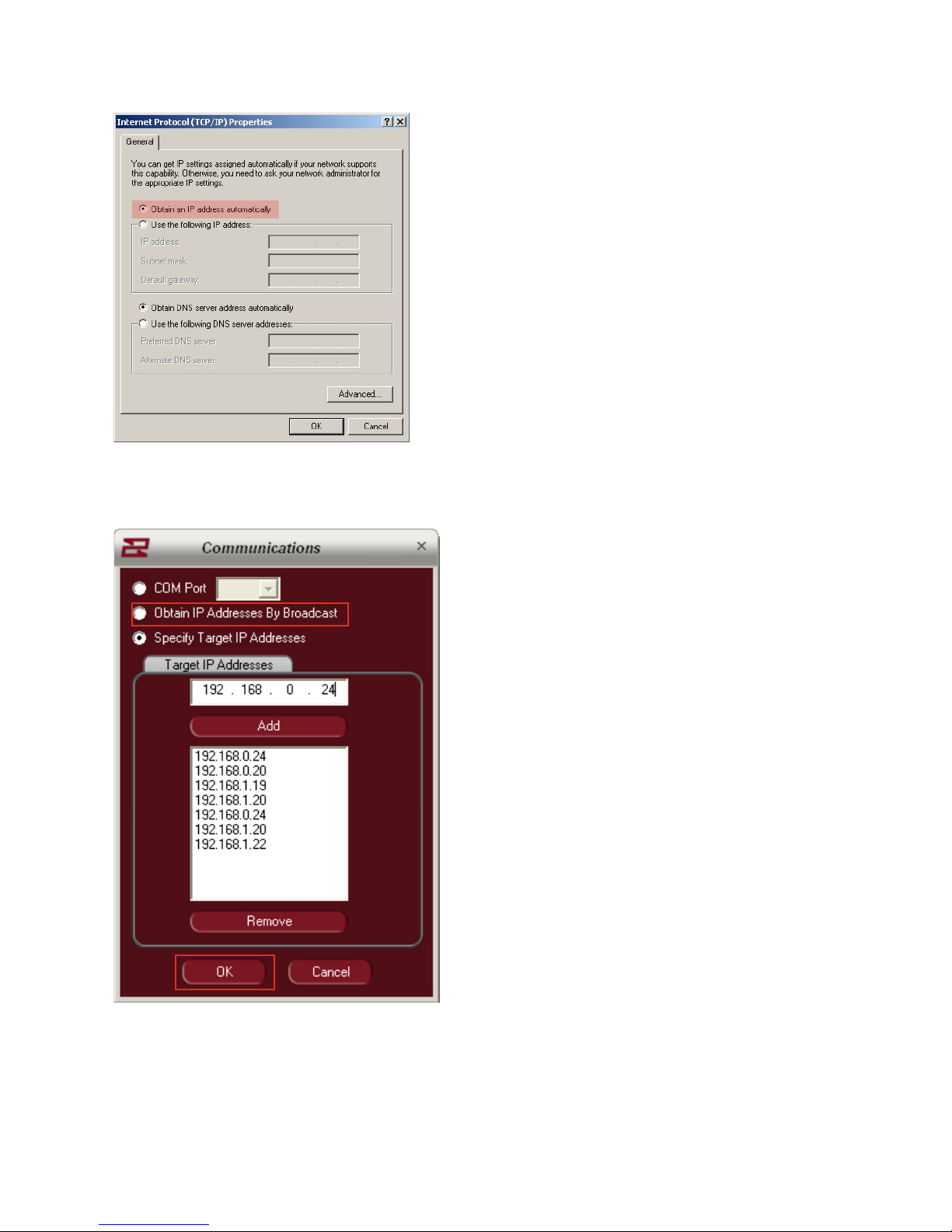
3) By default, most computers will already have the
“Obtain an IP address automatically checkbox
checked. If not – check it.
The computer is now set to communicate with a
Network Hub and obtain IP addresses through the
hub automatically.
Now that the computer is set to receive IP Addresses automatically, we must congure the EAWPilot
software to do the same
1) From the EAWPilot homepage, select “Tools”
and then “Communications”. This opens up the
“Dialog” menu within Pilot.
2) Check the box for “Obtain IP Address By
Broadcast”. This puts EAWPilot into dynamic IP
Address mode. Then press “OK” to conrm your
selection.
No other changes are necessary. When the
EAWPilot software is set to poll for connected
devices, the network hub will automatically
designate IP Addresses to any connected units.
Page 10
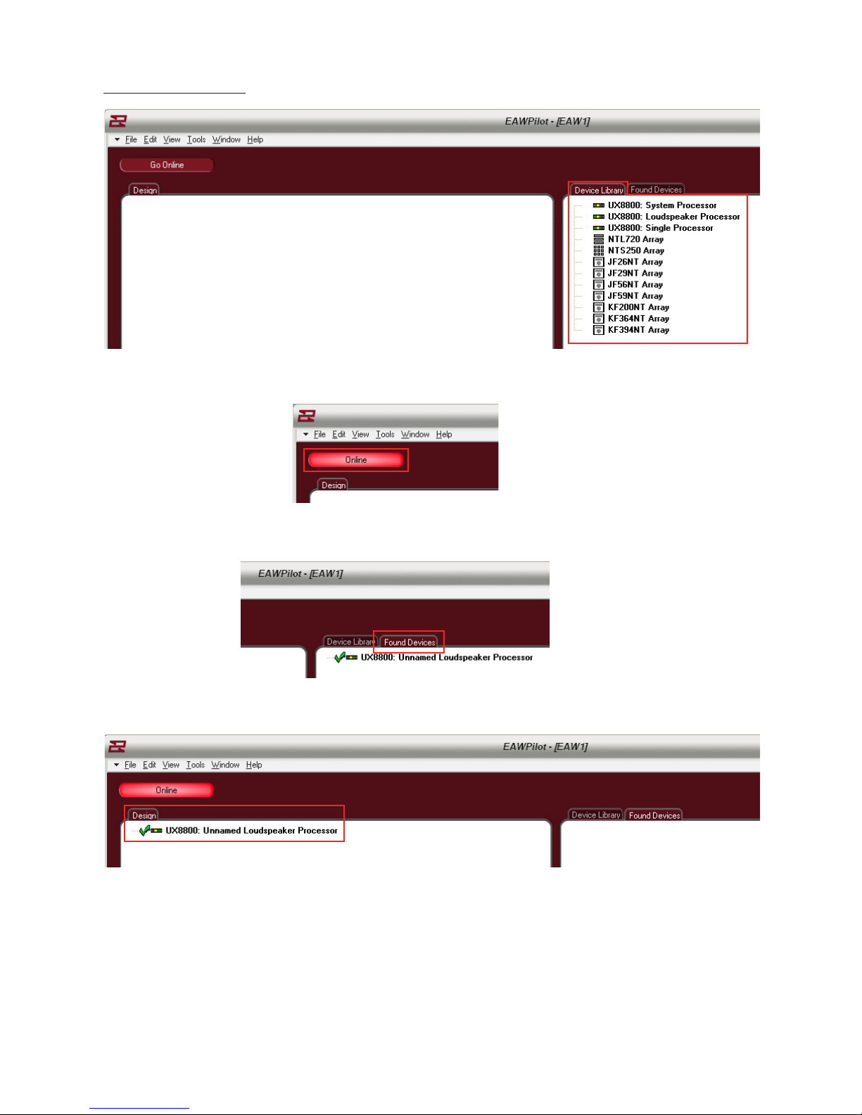
EAWPilot Homepage
The “Device Library” page is a listing of all supported hardware within the Pilot software. These “virtual
devices” can be used for building settings o-line and downloading to connected units later.
The button marked “online” brings EAWPilot online to any connected units. This will initiate the polling
process as the software searches for connected devices.
When the polling process is complete, connected units will be listed under “Found Devices”.
To begin the design process, a found device must be dragged over to the “Design” column of the page.
This is accomplished with a left-click and drag from your mouse.
The exclamation point will turn into a “check” when the software has conrmed that communication
to the UX8800 is ready.
Page 11
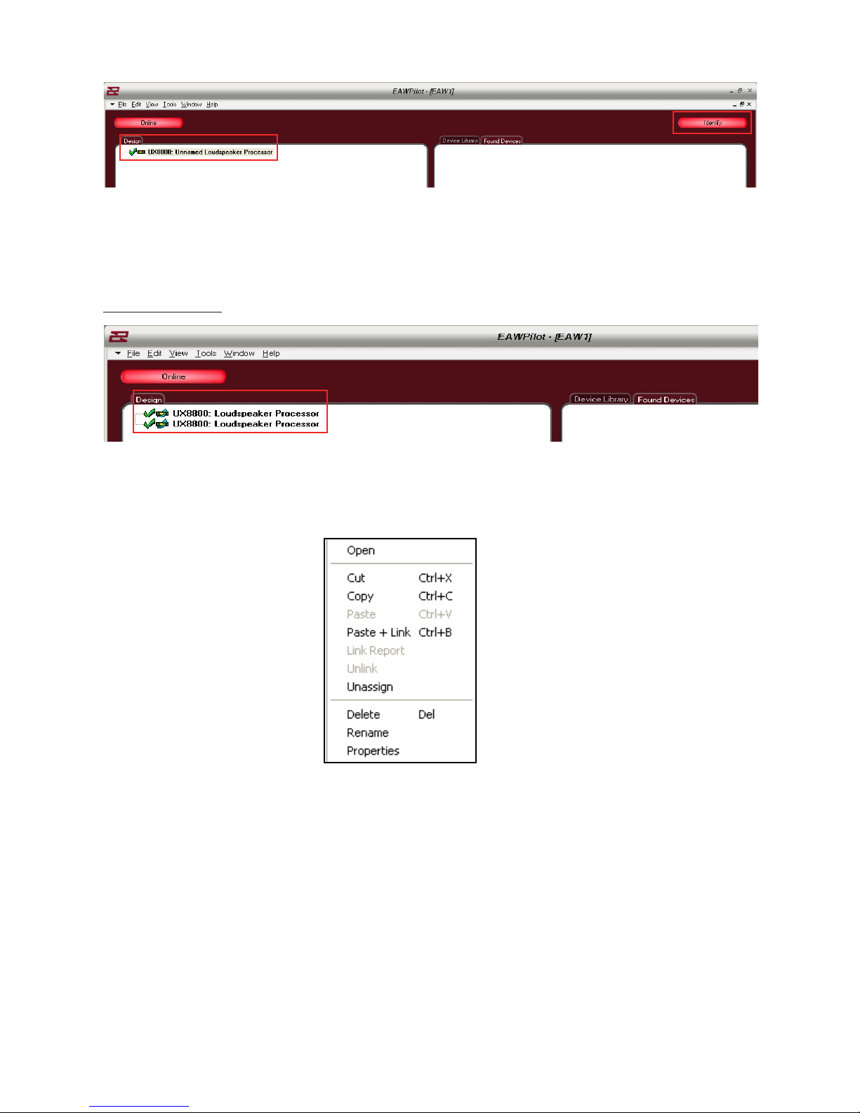
By highlighting a unit in the design column and then selecting the “identify” button, you can visually
match the hardware to the software as the output buttons on the physical UX8800 will scroll left and
right. Other U-Net capable devices may show this in a dierent manner.
Linking UX8800’s
If so desired, an entire UX8800 may be linked to another. Using this option greatly speeds up the time
it takes to program (e.g. House Left and House Right linked).
The linking process follows a hierarchy. Right click on the upper UX8800 to open the options menu.
Open - Opens the Processor Page for the selected UX8800
Cut - Removes the selected UX8800 from the Design List
Copy - Copies all parameters of the selected UX8800
Paste - Pastes all parameters to another selected UX8800
Paste + Link - pastes all parameters to another selected UX8800 and links the devices for all
future parameters
Delete - Deletes selected UX8800 from the Design Column
Rename - Allows the UX8800 to be renamed
Page 12

Link Report / Unlink - Only available when UX8800’s have already been linked
Link Report - Opens link report feature
Unlink - Unlinks the selected UX8800
Processor - Name of linked processor
Channel - Channels linked (All)
Linked Control - Specic functions that have been linked
OK - Conrm and escape the link report
Unlink - Unlink a selected parameter or channel
Unlink All - Unlink all channels and parameters
Note: Other linking options are available within the EAWPilot map windows
Page 13

The Map Page
Double-clicking on any unit listed in the “Design” column will open its associated Map Page
The UX8800 and Pilot communication is duplexing meaning that changes made via computer update
the unit immediately while changes made on the unit will update the software immediately.
Page 14

The Map Page
The “Map” page of the Pilot software gives the user an overview of the UX8800’s setup. While doubleclicking on most of the boxes in the map screen will take the user to an associated page, there are a
couple of functional buttons and menus directly on the map page.
Map Page
The mute buttons are all functional on the map page. You can also right click over any of the buttons
to copy and paste settings to another channel of the processor. This is especially helpful when
matching identical parameter layouts to other channels of the device. Simply right click over the
button, select copy, right click over the destination of the parameters and select paste. You may also
link the two channels at this stage so that any changes made to one channel will automatically be
copied to the other channel.
Page 15

Parameters that are linked will turn tan in color as an indicator to the operator that changes made
to one channel will also be applied to the other. All 4 input channels of the UX8800 may be linked if
desired or any portions of the input channels.
Copy – Ctrl+C – Stores all parameters in a temporary memory buer
Paste – Ctrl+V – Pastes these parameters to the destination
Paste+Link – Ctrl+B – Copies parameters and also links the feature
Link Report - Opens link report page (shows what links have been made)
Unlink – Unlinks the particular channel from the other
Page 16
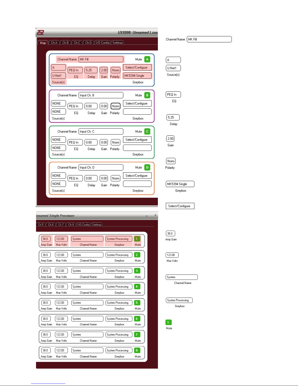
Channel Name – User Dened on input tabs
Source of Input x 2
EQ in or out?
Delay - Pre-delay applied (if any)
Gain
Polarity Normal Or Reversed?
Greybox Selected
Shortcut to Greybox page
Amplier Gain
Amplier maximum voltage output
Channel name (dened on I/O Cong page)
Greybox Applied
Mute (toggle on or o)
Page 17
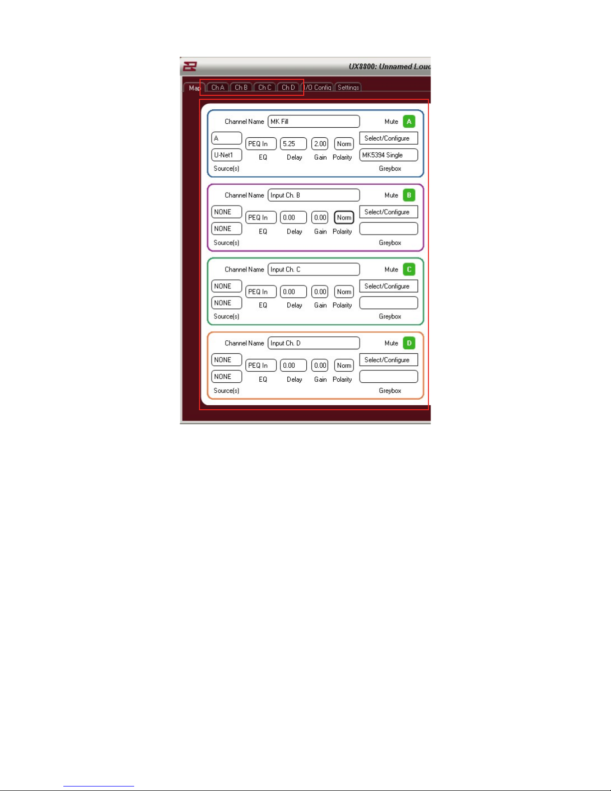
Any of the 4 input channel tabs can be accessed either by double-clicking within their respective Map
areas or by selecting the channel via the tabs at the top of the page.
Page 18
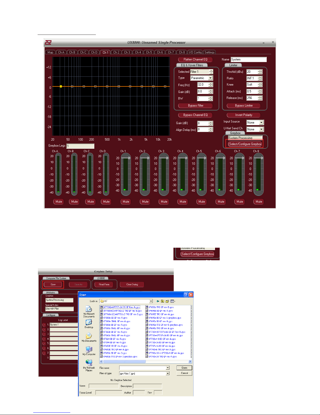
Conguring A Greybox
By default, the Pilot software will launch a completely open processor allowing the user to enter in his
own parameters.
Since we are choosing to use EAW factory presets, we must load a preset into the software and
UX8800, starting with one of the processors empty output channels..
Click on the button marked: Select / Congure Greybox
To browse for a greybox le, click
on the “Open” button
This opens the greybox browser
allowing the user to select from
dozens of precongured greybox
les. Select the appropriate le for
your application and click “open”
to open the le into EAWPilot
Page 19
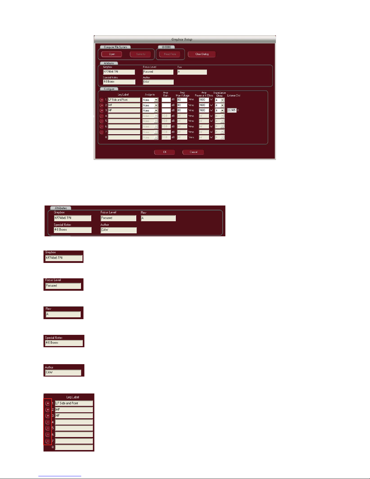
The selected greybox le (in this case a KF740 x 6) is loaded into the software
Before the greybox can be considered “optimized”, there are a few parameters to adjust.
“Attributes” describes the greybox that you have selected (not adjustable)
Title Of Greybox
Focus Level (not all greyboxes are Focused. These are labeled as “Legacy” greyboxes)
Greybox revision number
Any notes associated with the greybox
Creator of the greybox
The various legs of the greybox will be listed under “Leg Label”. The layout of these legs cannot be changed.
Note: Greybox legs can be duplicated to open leg channels. If the user wants to
create for example, an extra HF output for the 740’s, simply click on the + button
to the left of the menu and that particular leg will duplicate itself to the next
available leg.
Page 20
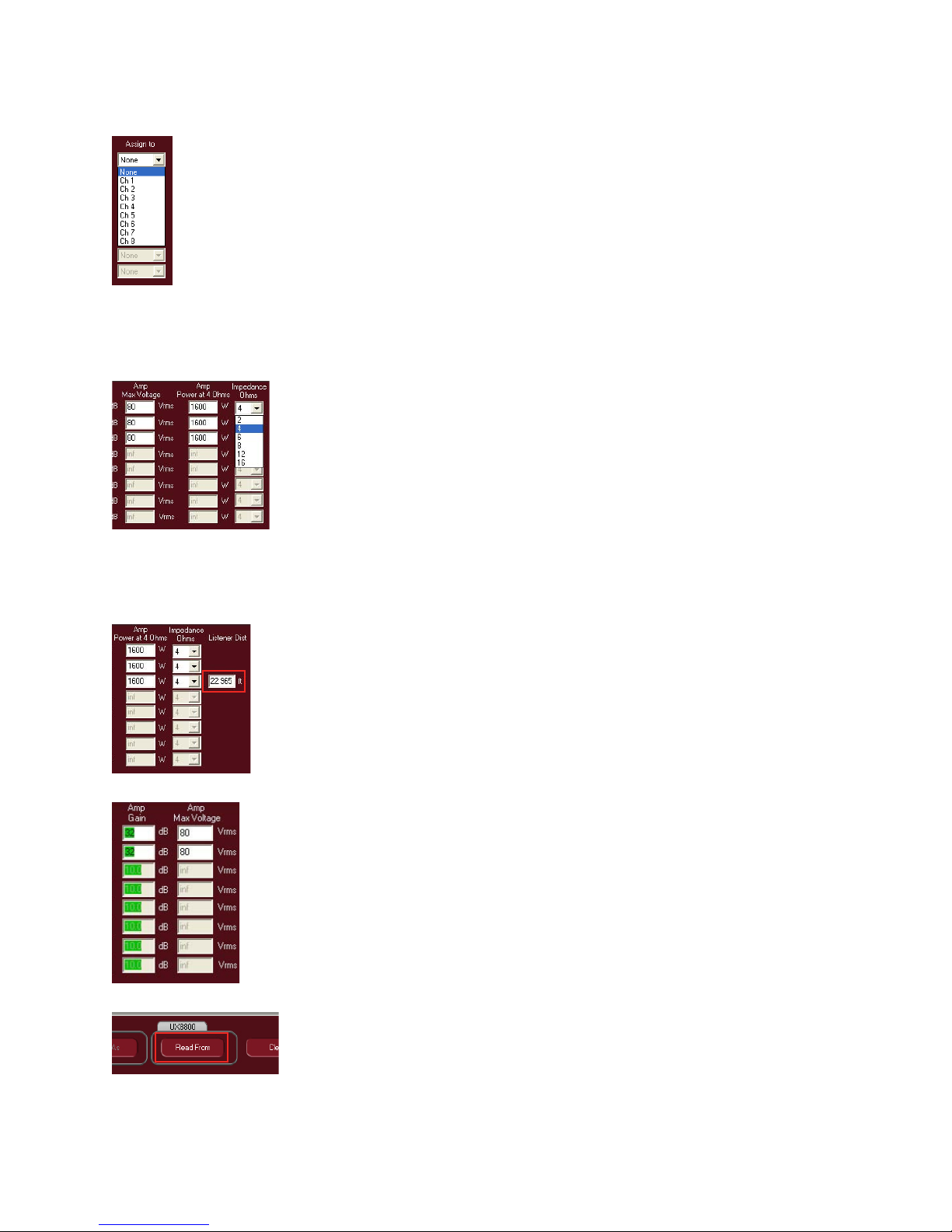
The legs must now be assigned to outputs on the UX8800. Use the dropdown menu to select from
outputs 1-8 (note: as an output is used up, it will disappear from the output dropdown menu)
Note: Even though the legs for the greybox are listed, they do not necessarily have to be
used. If any portion of the greybox is not required, do not give it an output assignment and
the leg will remain dormant. You may now use this output on other input channels.
A critical step in properly conguring the greybox is entering in the appropriate information for
amplier gain and amplier max voltage.
Amplier gain information is needed for the UX8800 to properly align bands
through crossover. Upon startup, these “Amp Gain” cells will be blank.
Amp Max Voltage is needed to properly calibrate the UX8800’s limiters. The
user must enter in the load being presented to the amplier and either the
max voltage to be applied at that ohmage or the max watts available at that
ohmage for that particular amplifer.
The nal step in conguring the greybox is adjusting the listener distance to update the air-loss
compensation feature on the UX8800.
The air loss compensation is a HF tapering lter that tailors the HF response
based on listener distance, temperature and humidity
Set the listener distance to the closest listener in the zone. If the listener
distance is set too far back in the zone, the HF compensation may be a bit much
for the people that are closer. It is more acceptable to have some dropo of HF
response.
If cells are left blank, the software will warn the user with either color coded
displays or with pop-up warnings that something is not correctly lled in.
If there are previously stored greyboxes on the UX8800 that you would like
to access, click on the “Read From” button to access them.
Page 21
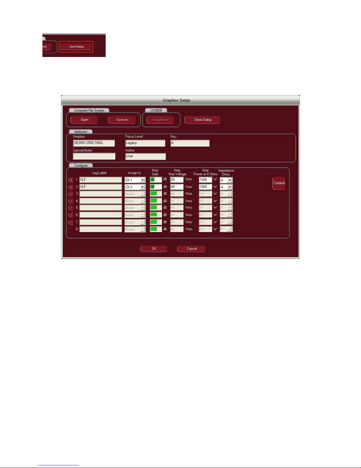
The currently selected greybox can be cleared from Pilot by clicking on the
“Clear Dialog” button.
If the user wishes to take advantage of the “Cardioid” feature contained in EAW Pilot, simply load one
subwoofer greybox and use the + (plus) button to add another and ll in the cells to congure the
greybox. This will open the cardioid feature.
Page 22
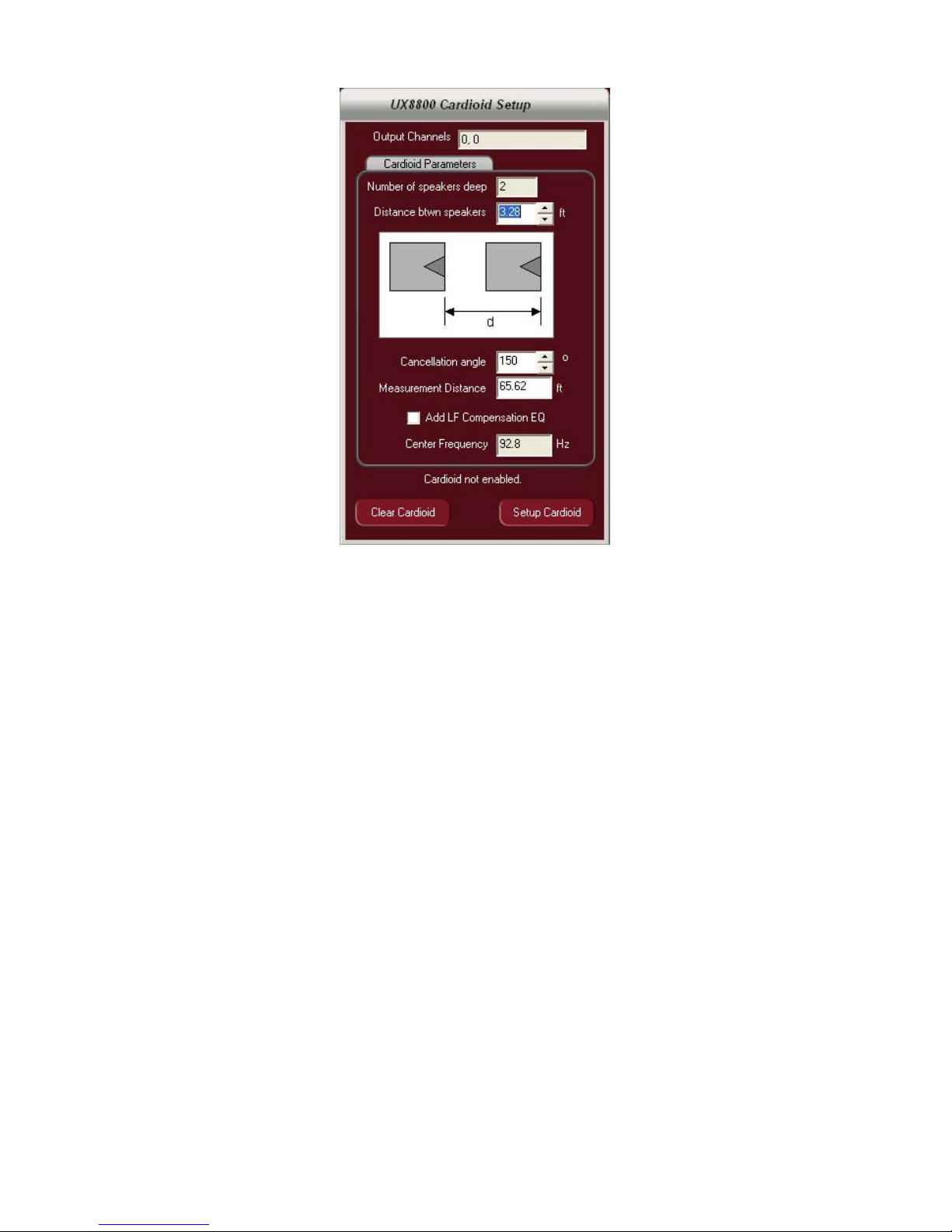
Conguring the cardioid feature:
Once the user has congured the subwoofers on the greybox “setup” page, they will be able to align
these subs to create a cardioid eect.
1. Determine the distance from the face of one subwoofer to another. The legend on the feature is
your guide to determining this. The spacing must be equal regardless of how many subs deep the
arrangement is.
2. Set the cancellation angle. This tells the software how wide or narrow you wish the forward
coverage of the subwoofer array to be.
3. Measurement distance – if close to the array, the angle changes. This parameter is used to adjust
the cancellation angle accordingly.
4. LF EQ Compensation – EAW’s technique for creating a cardioid does so at all frequencies but also
creates a 6 dB per octave roll o in the extreme low end below the center frequency. This selection
box applies a +4dB compensation EQ to make up for this loss.
5. Center Frequency – Sets the center frequency below which the LF Compensation EQ will be
applied.
6. Once the data has been entered, hit the “Setup Cardioid” button to create the pattern (note: even
though the delay times are not displayed in Pilot for the Cardioid, it has been implemented)
7. Hitting the “Clear Cardioid” button cancels the feature.
Page 23
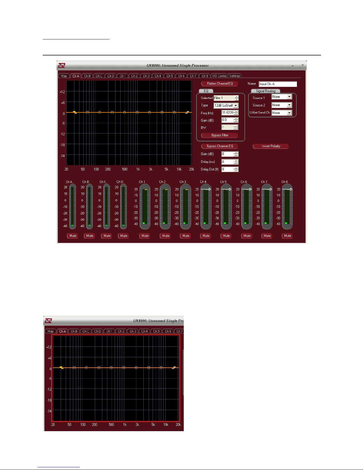
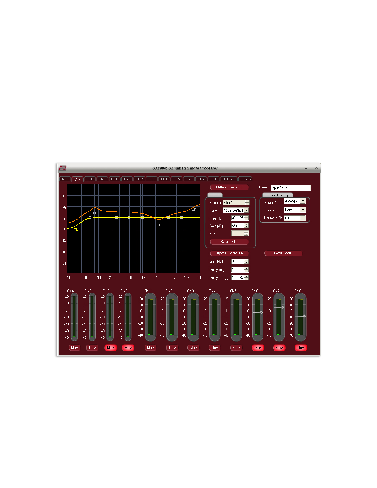
Equalizer / Gain / Delay
Direct Value Adjustment
Once a greybox is installed, equalization for the channel is done on its input processor tab (A,B,C,D).
EAWPilot allows two dierent methods for setting equalizers. The user may elect to manually type in
all of the EQ parameters or use the associated spinners to set parameters. Alternately, you may also use
the drag and drop method within the graphical display to set EQ points.
Note: The drag and drop method can be used for coarse adjustment and then ne tuned using the
spinners or by manually typing in a value.
Graphical Display Area
Page 24
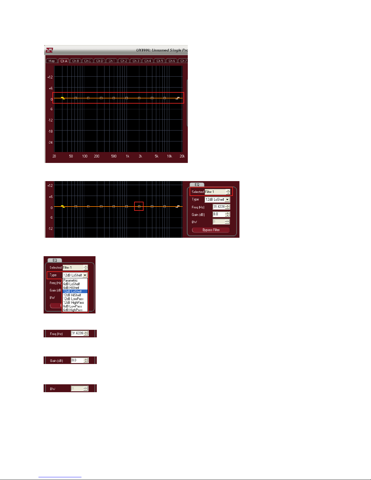
EQ Points (10 available + LPF and HPF)
Select Filter to modify or click on a square within the Display area.
Select Filter Type by using dropdown menu
Adjust the Frequency of the Filter (20Hz – 20000Hz)
Adjust The Gain Of The Filter (+/- 15dB)
Adjust the Width of the Filter using Q or BW (adjusted under tools menu)
Page 25
Alter the name of the input channel here
If desired, the input source(s) can be changed here by using the dropdown menus
The polarity of the channel can be inverted by clicking on this button.
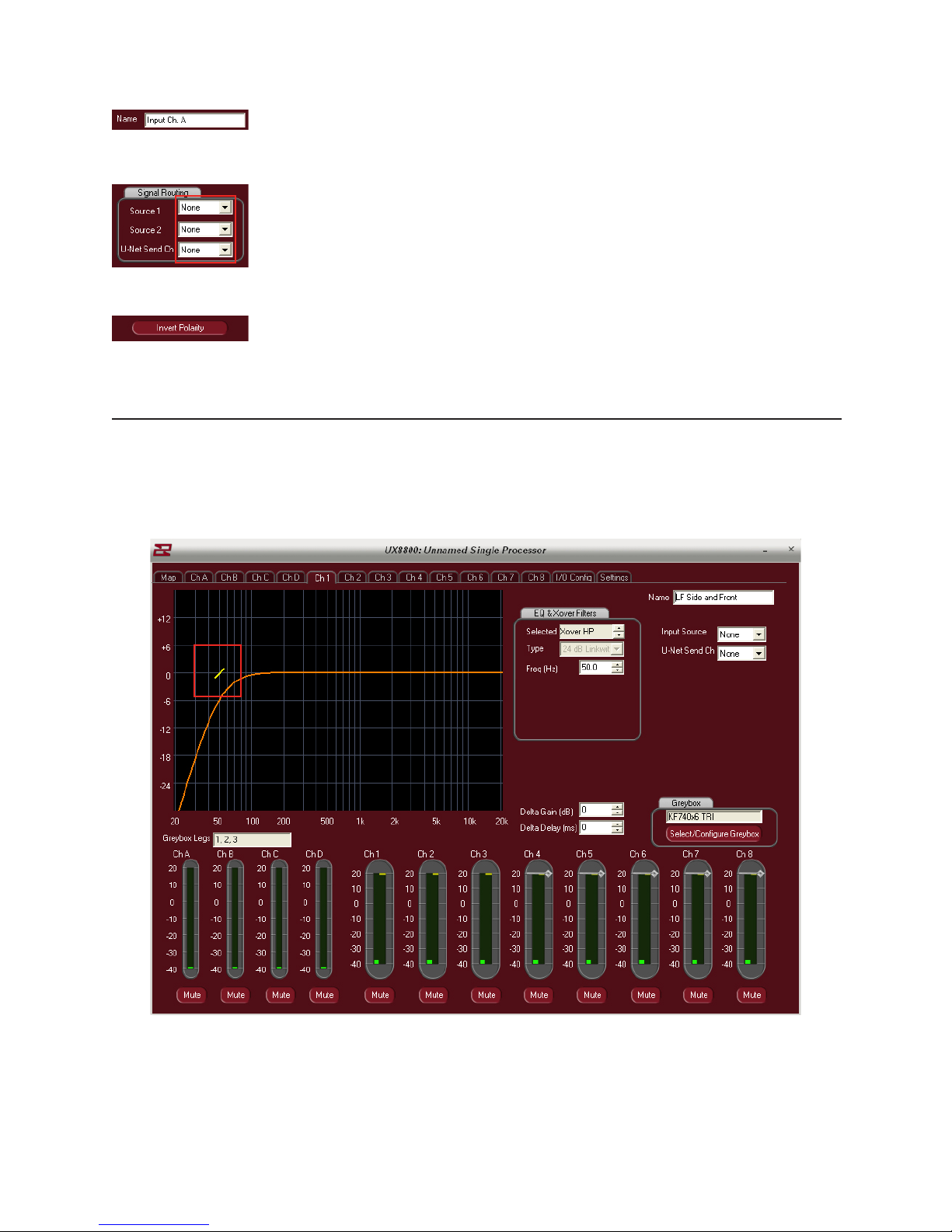
Drag And Drop Adjustment
From any of the greyboxes output tabs, left click and drag the slash mark to alter the high pass lter.
Note: Once the HPF has been dragged, the software will automatically switch the slope from a
12dB Butterworth to a 24dB Linkwitz-Riley. The L/R lter has better integration properties than the
Butterworth for adjoining to subwoofers.
Page 26

On the input tab for the greybox, left clicking and dragging the squares will implement the available
10 parametric EQ’s.
Left click and drag the small yellow dots anking the EQ and move left or right to adjust the Q of
the lter.
Left click and drag the Z marks to alter the Lo or Hi shelving lters.
Page 27

Bypass the selected lter by clicking the “Bypass Filter” button.
Bypass ALL EQ’s by clicking on the “Bypass Channel EQ” button.
The entire EQ set can be returned to at with a couple of simple clicks.
First click on the “Flatten Channel EQ” button
The software will warn you that you are about to lose all of your
equalization for that channel.
If this is your intention, click OK or press cancel to go back to the
input screen.
Use the spinner to adjust the
gain of the input signal (-99 to
+15 dB)
The adjustment is visualized
by movement of the orange
bar within the graphical
display area.
Up to 1200ms of delay is available to each input channel. Use the spinner to adjust the delay or simply
type the value directly into the box.
Alternatively, you may want to enter in delay as a function of distance? Use the spinner or direct value
input to alter the distance value (up to 412m)
Page 28

I/O Conguration Page
The I/O Cong page is designed to allow the user to easily access input as well as U-Net assignments
for the UX8800. It is also the place to enter in names for both the input and output channels of the UX.
Using the dropdown boxes, select up to 2 sources for each input of the UX8800.
Note: The physical connections to the back of the UX8800 do not necessarily
have to follow through to the processor. For example, you may have a signal
coming in on the physical D input connector on the back of the processor.
On the I/O Cong page, you can have this physical input feed the A input of
the processor.
If desired, the input can now be sent on to other U-Net capable devices via
the connectors on the rear of the UX8800. Up to 64 Channels of U-Net are
available
Page 29

Input and Output names can be changed on the I/O Page by clicking in their respective title boxes.
Page 30

Settings Page
Rename the UX8800 to any name desired here (e.g. House Left)
Convert the 4 inputs of the UX8800 from analog to digital here
(Note: A&B – C&D combine when AES is selected)
Enter in the current temperature and relative humidity of the current environment to calibrate the high
frequency compensation feature.
Select from 5 dierent predetermined temperature / humidity zones.
The “Manage GreyBox Storage” feature is used to transfer GreyBoxes from le locations on your PC to
the UX8800 or retrieve Greyboxes from a UX8800 to store on your PC. Click here to open this feature
Page 31
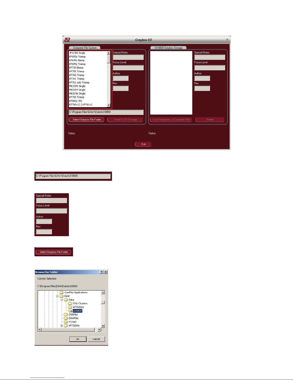
List of Greyboxes in the currently selected le folder from your computer.
Location of the les on your PC
Attributes of the currently selected GreyBox
Browse your computers le system for other GreyBoxes to recall
Browse your computers le system for other GreyBoxes to recall
Page 32
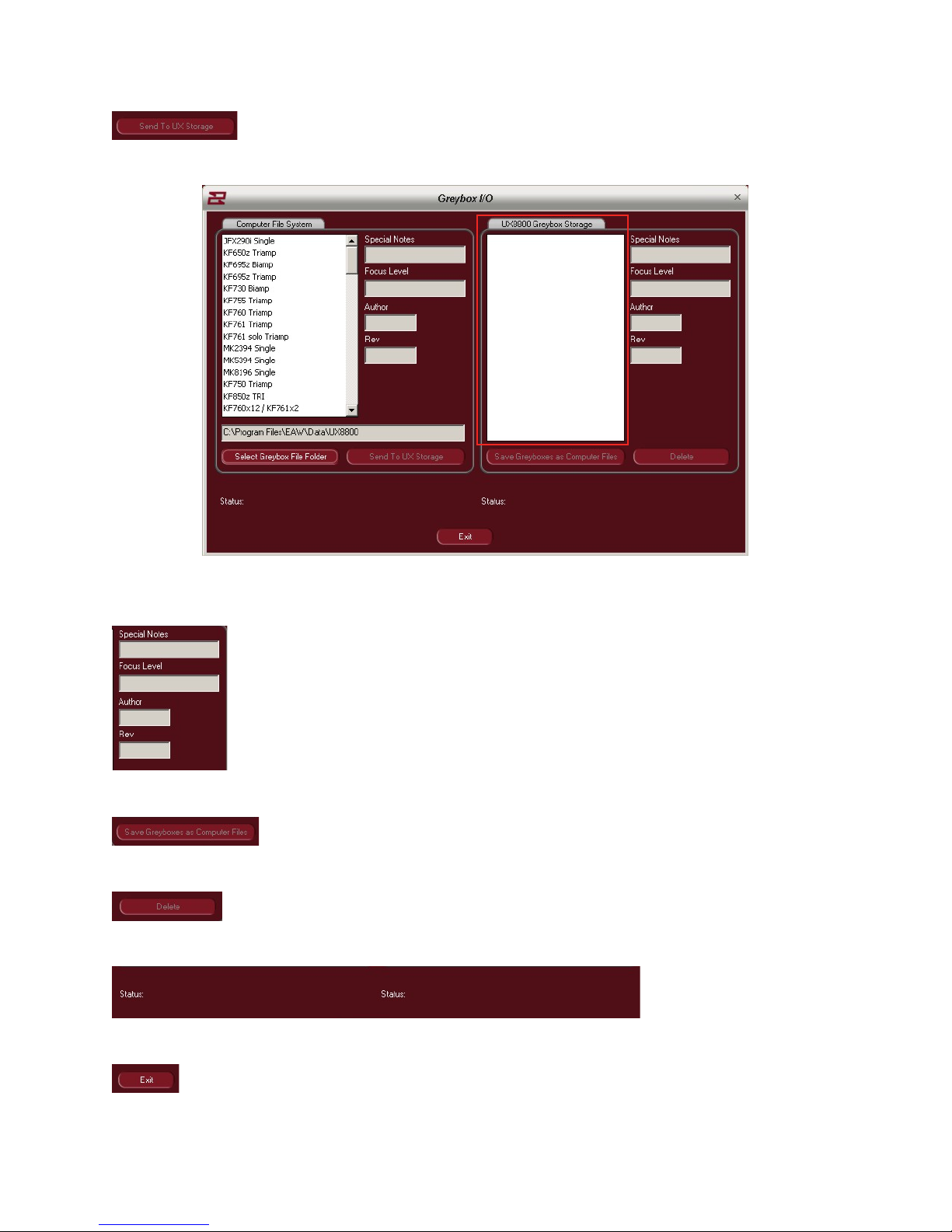
Send a selected GreyBox to the UX8800 storage
Greyboxes currently stored on the UX8800 – if any.
GreyBox le attributes
Select a GreyBox for storage to Your PC.
Delete GreyBox from the UX8800
File transfer status
Exit “File Management” feature
Page 33
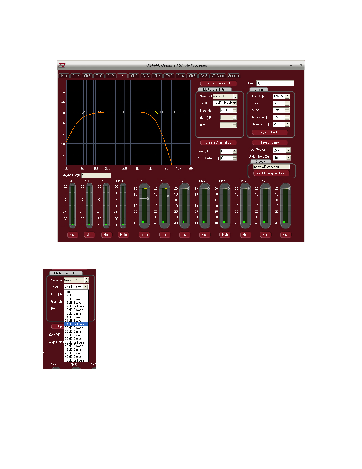
Open System Processing
If processor outputs are not loaded for greybox usage, they can be used for generic processing.
High and low pass lters may be set to create crossover settings for any desired product.
Page 34
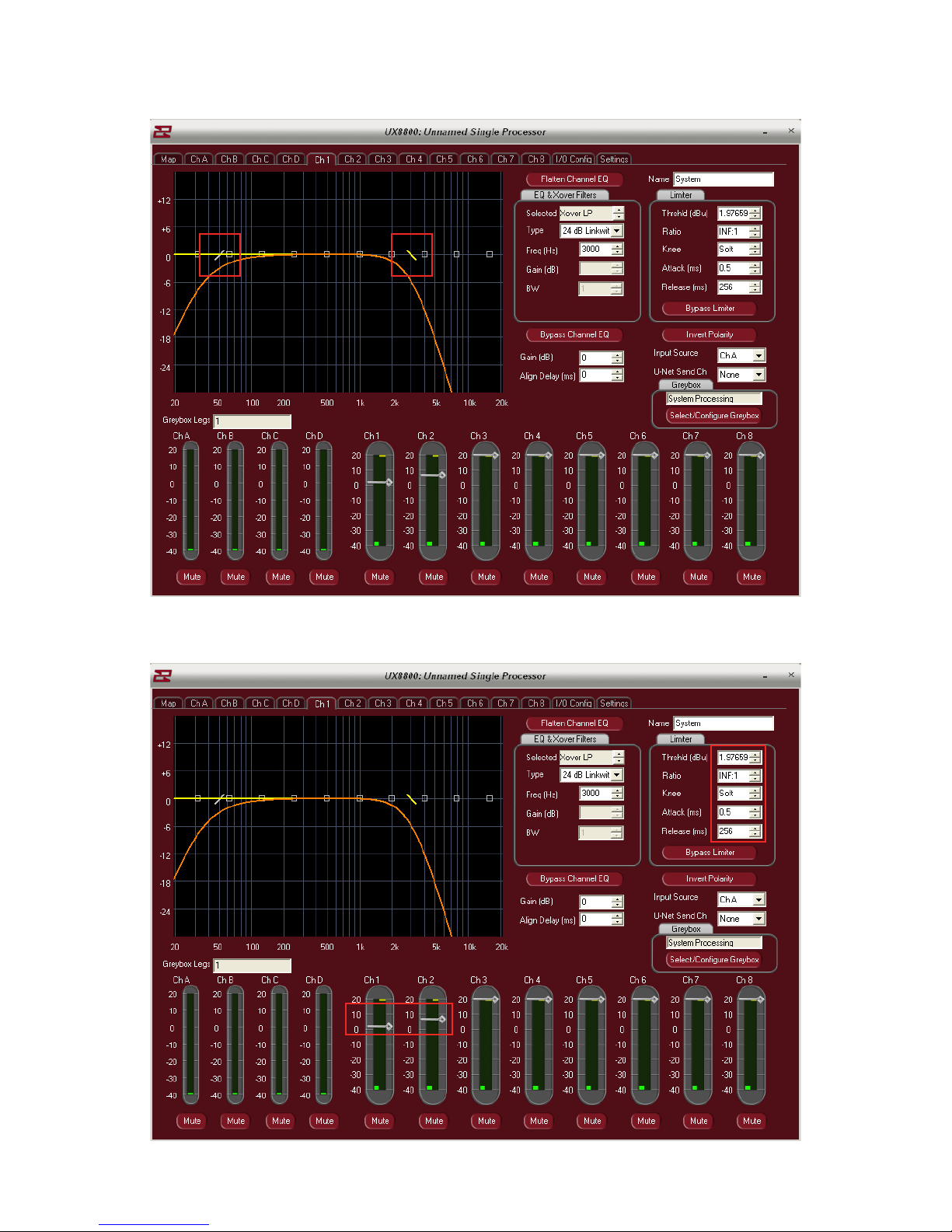
Filters may also be set with click and drag.
Limiters may be custom set by entering absolute numeric values. Thresholds can be modied by left
click and drag of the threshold bars.
Page 35

Notes
Page 36

Notes
 Loading...