

EAW DX-RVC Quick Start Manual
DX-RVC PREDEFINED FUNCTIONS
DX-RVC Remote Volume Control (For DX810 Applications)
Switch Positions *
ID 1 through 8 Function
0 00000000 Input Level 1A
1 10000000 Input Level 1B
2 01000000 Input Level 1C
3 11000000 Input Level 1D
4 00100000 Input Level 1E
5 10100000 Input Level 1F
6 01100000 Input Level 1G
7 11100000 Input Level 1H
8 00010000 Input Level 1I
9 10010000 Input Level 1J
10 01010000 Input Level 2A
11 11010000 Input Level 2B
12 00110000 Input Level 2C
13 10110000 Input Level 2D
14 01110000 Input Level 2E
15 11110000 Input Level 2F
16 00001000 Input Level 2G
17 10001000 Input Level 2H
18 01001000 Input Level 2I
19 11001000 Input Level 2J
20 00101000 Input Level 3A
21 10101000 Input Level 3B
22 01101000 Input Level 3C
23 11101000 Input Level 3D
24 00011000 Input Level 3E
25 10011000 Input Level 3F
26 01011000 Input Level 3G
27 11011000 Input Level 3H
28 00111000 Input Level 3I
29 10111000 Input Level 3J
30 01111000 Input Level 4A
31 11111000 Input Level 4B
32 00000100 Input Level 4C
33 10000100 Input Level 4D
34 01000100 Input Level 4E
35 11000100 Input Level 4F
36 00100100 Input Level 4G
37 10100100 Input Level 4H
38 01100100 Input Level 4I
39 11100100 Input Level 4J
40 00010100 Input Level 5A
41 1001010 Input Level 5B
42 01010100 Input Level 5C
43 11010100 Input Level 5D
44 00110100 Input Level 5E
45 10110100 Input Level 5F
46 01110100 Input Level 5G
47 11110100 Input Level 5H
48 00001100 Input Level 5I
49 10001100 Input Level 5J
50 01001100 Input Level 6A
51 11001100 Input Level 6B
52 00101100 Input Level 6C
53 10101100 Input Level 6D
54 01101100 Input Level 6E
55 11101100 Input Level 6F
56 00011100 Input Level 6G
57 10011100 Input Level 6H
58 01011100 Input Level 6I
59 11011100 Input Level 6J
60 00111100 Input Level 7A
61 10111100 Input Level 7B
62 01111100 Input Level 7C
63 11111100 Input Level 7D
64 00000010 Input Level 7E
65 10000010 Input Level 7F
66 01000010 Input Level 7G
67 11000010 Input Level 7H
68 00100010 Input Level 7I
69 10100010 Input Level 7J
70 01100010 Input Level 8A
71 11100010 Input Level 8B
72 00010010 Input Level 8C
73 10010010 Input Level 8D
74 01010010 Input Level 8E
75 11010010 Input Level 8F
76 00110010 Input Level 8G
77 10110010 Input Level 8H
78 01110010 Input Level 8I
79 11110010 Input Level 8J
80 00001010 Output Level A
81 10001010 Output Level B
82 01001010 Output Level C
83 11001010 Output Level D
84 00101010 Output Level E
85 10101010 Output Level F
86 01101010 Output Level G
87 11101010 Output Level H
88 00011010 Output Level I
89 10011010 Output Level J
90 01011010 Group Level 1
91 11011010 Group Level 2
92 00111010 Group Level 3
93 10111010 Group Level 4
94 01111010 Group Level 5
95 11111010 Group Level 6
96 00000110 Group Level 7
97 10000110 Group Level 8
98 01000110 Group Level 9
99 11000110 Group Level 10
100 00100110 Group Level 11
101 10100110 Group Level 12
102 01100110 Group Level 13
103 11100110 Group Level 14
104 00010110 Group Level 15
105 10010110 Group Level 16
106 01010110 Group Level 17
107 11010110 Group Level 18
108 00110110 Group Level 19
109 10110110 Group Level 20
110 01110110 Group Level 21
111 11110110 Group Level 22
112 00001110 Group Level 23
113 10001110 Group Level 24
114 01001110 Group Level 25
115 11001110 Group Level 26
116 00101110 Group Level 27
117 10101110 Group Level 28
118 01101110 Group Level 29
119 11101110 Group Level 30
120 00011110 Group Level 31
121 10011110 Group Level 32
122-255 Reserved for future
updates
Switch Positions
ID 1 through 8 Function
DX-RVC Remote Volume Control (For DX8 Applications)
Switch Positions *
ID 1 through 8 Function
0 00000000 Input Level 1A (1)
1 10000000 Input Level 1A (2)
2 01000000 Input Level 1B (1)
3 11000000 Input Level 1B (2)
4 00100000 Input Level 2A (1)
5 10100000 Input Level 2A (2)
6 01100000 Input Level 2B (1)
7 11100000 Input Level 2B (2)
8 00010000 Input Level 3A (1)
9 10010000 Input Level 3A (2)
10 01010000 Input Level 3B (1)
11 11010000 Input Level 3B (2)
12 00110000 Input Level 4A (1)
13 10110000 Input Level 4A (2)
14 01110000 Input Level 4B (1)
15 11110000 Input Level 4B (2)
16 00001000 Input Level 5A (1)
17 10001000 Input Level 5A (2)
18 01001000 Input Level 5B (1)
19 11001000 Input Level 5B (2)
20 00101000 Input Level 6A (1)
21 10101000 Input Level 6A (2)
22 01101000 Input Level 6B (1)
23 11101000 Input Level 6B (2)
24 00011000 Input Level 7A (1)
25 10011000 Input Level 7A (2)
26 01011000 Input Level 7B (1)
27 11011000 Input Level 7B (2)
28 00111000 Input Level 8A (1)
29 10111000 Input Level 8A (2)
30 01111000 Input Level 8B (1)
31 11111000 Input Level 8B (2)
32 00000100 Output Level A (1)
33 10000100 Output Level A (2)
34 01000100 Output Level B (1)
35 11000100 Output Level B (2)
36 00100100 Output Level A&B (1)
37 10100100 Output Level A&B (2)
38 01100100 Group Level 1 (1)
39 11100100 Group Level 1 (2)
40 00010100 Group Level 2 (1)
41 10010100 Group Level 2 (2)
42 01010100 Group Level 3 (1)
43 11010100 Group Level 3 (2)
44 00110100 Group Level 4 (1)
45 10110100 Group Level 4 (2)
46 01110100 Group Level 5 (1)
47 11110100 Group Level 5 (2)
48 00001100 Group Level 6 (1)
49 10001100 Group Level 6 (2)
50 01001100 Group Level 7 (1)
51 11001100 Group Level 7 (2)
52 00101100 Group Level 8 (1)
53 10101100 Group Level 8 (2)
54-255 Reserved for future
updates
Switch Positions
ID 1 through 8 Function
Each of the predefined functions has two IDs (1) and (2) to allow two remote controls
to perform the same function.
*Switch Positions: 1 = ON; 0 = OFF
*Switch Positions: 1 = ON; 0 = OFF
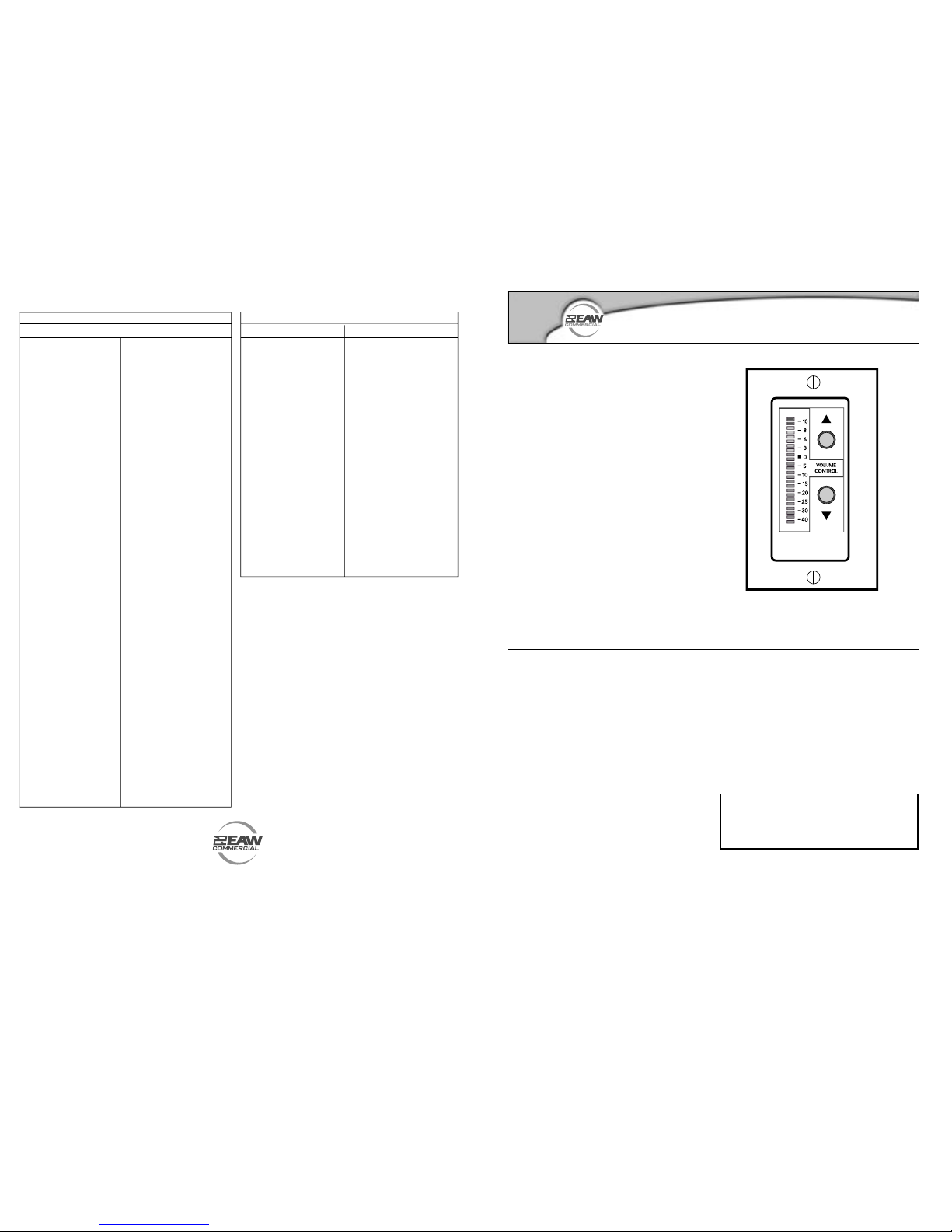
The DX-RVC is a real-time remote volume
control for use with the DX8 and DX810 Digital
Audio Mixer/Signal Processor. The DX-RVC can be
programmed to operate the volume for any of the
eight inputs, any output, or grouped outputs. The
predened functions are programmed via the eight
DIP-switches on the back of the circuit board. Up
to nine remote controls (including the DX-RVC
and the DX-SW4) can be connected to the DX8 or
DX810 REMOTE BUS connector.
DX-RVC
Remote Volume Control
Quick-Start Guide
SAFETY FIRST!
Before connecting and using the equipment,
please read this Quick-Start Guide carefully
and keep it for future reference.
WARNING! This equipment has been
designed to be installed by qualied
professionals only! There are many factors to
be considered when installing professional
sound reinforcement systems. Some of these
factors include mechanical and electrical
considerations, as well as acoustic coverage
and performance. LOUD Technologies strongly
recommends that this equipment be installed
only by a professional sound installer or
contractor.
1. Never install, connect, or disconnect the
remote control with the DX8 or DX810
power supply on.
2. Before applying power to the DX-RVC, make
sure the wiring is correct as described in
this Quick-Start Guide.
CAUTION: To avoid the risk of electric
shock, never allow this equipment to be
exposed to rain or dampness.
EAW Commercial | One Main Street | Whitinsville, MA 01588 USA | www.eawcommercial.com
TEL: toll free in US & Canada 888.337.7404 | TEL outside US 425.892.6503 | FAX: 425.485.1152
UK 44.1268.570.808 | FAX 44.1268.570.809
Part No. 910-298-90 Rev. B 06/04 © 2004 LOUD Technologies Inc. All Rights Reserved.
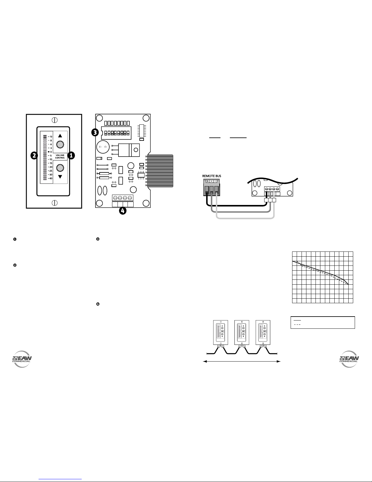
FRONT PANEL FEATURES
UP/DOWN VOLUME CONTROL
Use to adjust the level for the Input, Output, or Group
assigned to the remote control. Duplicates the function of the UP/DOWN buttons on the DX8/DX810
front panel.
LED DISPLAY
Indicates the level setting of the Input, Output,
or Group assigned to the remote control. "0" corresponds to "10" on the DX8/DX810 front panel
LED display, which is unity gain. "+10" corresponds
to "OL" on the front panel LED display, which is
maximum gain.
REAR PANEL FEATURES
PREDEFINED FUNCTION SELECTION SWITCH
This 8-position DIP switch provides 256 unique func-
tions that can be assigned to the DX-RVC remote.
Refer to the chart on the back page for a list of all
predened functions currently available.
Each remote control must have the selection switch
set to a unique ID. When the DX8/DX810 is rst
turned on, it polls the REMOTE BUS and identies the
remote controls connected to it by each unique ID.
Many of the predened functions have two ID addresses assigned to it to allow two remote controls
to be connected to a DX8 that both control the
same function.
CONNECTOR (J2)
Connect the wires from the DX8/DX810 REMOTE
BUS directly to this connector. Strip the wire back
about 1/4", insert the wire as far as it will go into
the connector and tighten down the screw with a
small slot-head screwdriver.
Use a high-quality three-conductor shielded cable
to make this connection, such as Belden 8451,
9451, or equivalent.
The connector is wired as follows:
Remote DX8/DX810
GND G (Ground)
A + (+ Data with +24V DC power)
B – (– Data with +24V DC power)
PWR N/C (This is for an external
power supply, described in the
next section)
R20
R21
R22
R23
R24
R25
R26
R27
C14
C7
R35
R1
R2
R3
C3
C4
C16
R34
R4
D3
D4
C9
U5
U2
C8
U6
J2
L2 L1
J4
S1
D2
J5
J3
R6
R7
C10
R5
GND
A
B
PWR
1
ON
FUNCTIO
N
2 3 4 5 6 7
8
INSTALLING THE DX-RVC
The DX-RVC can be installed in a single
standard electrical box, or in a double-gang box
along with a second DX-RVC or DX-SW4 remote
control.
CONNECTING MULTIPLE
REMOTE CONTROLS
Up to nine remote controls can
be connected to the DX8/DX810
REMOTE BUS. The maximum
length of the cable depends on the
type of cable used and the number
and type of remote controls used
in the system.
As a general rule, using 22
gauge wire (at 0.014 Ω/ft. and
34 pF/ft.), one remote can be up
to 3000 feet away, five remotes
can be up to 2500 feet away, and eight remotes
can be up to 500 feet away before transmission
losses become a factor.
To Next Remote
Total Distance Dependent on T
ype of Cable Used
From DX8
C8
J2
L2 L1
R5
GND
A
B
PWR
GND
A
B
DX8/DX810 DX-RVC
USING AN EXTERNAL POWER
SUPPLY
The DX-RVC is powered by the DX8/DX810
over the data lines. An external power supply
can be used by removing jumpers J3 and J5
from the DX-RVC circuit board, and connecting
a power supply rated at 9 to 16V AC or DC
to the PWR terminal on the connector (J2). A
number of "wall-warts" or bell transformers are
readily available from local electrical supply
houses with output ratings between 9V and
16V. Allow 25mA per remote.
DISTANCE CHART FOR DX-RVC CABLE
Feet of Cable versus
Maximum Number of 2-Button Remotes
Feet of Cabl
e
Belden 8451 (22 AWG, 34pf/f
t)
Belden 1192A (24 AWG, 39pf/f
t)
0
0
250
500
750
1000
1250
1500
1750
2000
2250
2500
2750
3000
3250
1
2
3
4
5
6
7
8
9
10
Number of 2-Button Remotes
 Loading...